182 | P a g e
DESIGN, ANALYSIS, OFEFFICIENT SOLAR POWER
OPTIMIZER FOR DC MICRO GRID SYSTEM
AJINKYA D. SALPE
Department of Electrical Engineering
Dr. Babasaheb Ambedkar Technological University,
Lonere, Dist.-Raigad, Maharashtra, (India)
ABSTRACT
This paper presents a high step-up gain Solar Power Optimizer (SPO) to harvests maximum energy from a photovoltaic (PV) panel and feed this energy to a DC micro -grid. The arrangement consists of coupled inductor and switched capacitor to increase voltage gain. The leakage inductance energy of the coupled inductor can be recycled to reduce voltage stress and power losses across the power device. Low voltages rating and low-conduction resistance power switch improves system efficiency by employing the incremental conductance algorithm method for the maximum power point tracking (MPPT). Because of its high tracking accuracy, the method is used in the energy harvest from PV systems. The planned SPO that have an input voltage range of 20 to 40 V and a maximum PV output power of 400 V/300 W are considered. The highest PV power conversion efficiency is 97%. The maximum MPPT accuracy is 99%. The above efficiency obtained is verified by using MATLAB Simulink.
Keywords
—High step-up voltage gain, Incremental conductance algorithm (ICA), Maximum power
point tracking (MPPT), Solar power optimizer (SPO).
I. INTRODUCTION:
Fossil fuels continue to be depleted, and their use has been instrumental to climate change, a problem that grows more severe each year. A photovoltaic (PV) power generation system, which uses a renewable resource, has been extensively used in emergency facilities and in generating electricity for mass use. A conventional PV gen-eration system is either a single- or a multi string PV array that is connected to one or several central PV inverters.Numerous series-connected PV modules are connected in the PV array to achieve the DC link voltage that is high enough to be connected toelectricity through the DC-AC converter. However, the power reduction that is caused by the shadow effect is an inevitable problem in a centralized PV system. The use of a micro inverter or ac module has recently been proposed for individual PV panels. Although this discrete PV power generation solution may partially eliminate the shadow problem, a micro inverterstructure constrains the system energy’s harvesting efficiency and entails high costs. A solar power optimizer (SPO) was developed as an
183 | P a g e
dc micro grid connection or through a dc–ac inverter for electricity. This passes through an SPO to a DC micro grid system. A 400 V DC- micro grid system was proposed as an energy-efficient distribution option for data center systems and telecommunication facilities. The SPO attempts to improve the use of distributed renewable resources and lower system cost. It may also potentially improve the efficiency of PV systems, has an anti-shadow effect, and can monitor the status of PV modules. Moreover, the dc-grid voltage is regulated by bidirectional inverter and battery tank. In case of low-loading condition, the redundant energy will store into battery or through bidirectional inverter to ac grid. A high step-up solar power optimizer (SPO) that efficiently harvests maximum energy from a photovoltaic (PV) panel then outputs energy to a dc-micro-grid. An SPO is used as a DC-DC converter with Maximum Power Point Tracking (MPPT), which increases PV panel voltage to optimum voltage levels for a dc micro-grid connection or through a DC-DC converter for electricity Fig.1 below shows a single PV panel’s energy. PV solar electricity together with solar thermal has the highest potential of allthe renewable energies since solar energy is a practically unlimited resource, available everywhere. [1-4]
Fig: 1 Configuration of multiple parallel SPO for a DC-micro grid system.
The proposed SPO is shown in fig.1.Its configuration is based on a high step-up DC–DC converter with an MPPT control circuit. The converter includes a floating active switch S and a coupled inductor T1 with primary winding N1, which is similar to the input inductor of a conventional boost converter capacitor C1, and diode D1 recycle leakage inductance energy from N1. Secondary winding N2 is connected to another pair of capacitors, C2 and C3, and to diodes D2 and D3. Rectifier diode D4 connects to output capacitor Co and load R. The duty ratio is modulated by the MPPT algorithm, which uses the hill climb/ perturb & observe method method that is employed in the proposed SPO. It detects PV module voltage Vpv and current Ipv to determine the increase and decrease in the duty cycle of the dc converter. Therefore, the MPP can be obtained by comparing instantaneous conductance I/V and incremental conductance dI/dV. The algorithm is programmed into TMS320LF2407A, a digital signal microprocessor.
Solar panel
MPPT
S1 C1 C2
D2
D1 D3
C3
N1
N2
DC
C0
Vbus
D4 DRIVER
184 | P a g e
Fig.2: Configuration of the proposed SPO.
1.1 The Proposed Converter Features
1) Its voltage conversion ratio is efficiently increased by using the switched capacitor and coupled inductor tech-niques.
2) The leakage inductance energy of the coupled inductor can be recycled to increase efficiency, and the voltage spike on the active switch is restrained.
3) The floating active switch isolates the PV panel’s energy during non-operating conditions, thereby preventing
any potential electric hazard to humans or facilities. The MPPT control algorithm exhibits high-tracking efficiency; hence, it is widely used in the energy harvesting of PV systems.
II. OPERATING PRINCIPLES
The operating principles for continuous conduction mode (CCM) and discontinuous conduction mode (DCM) are given below.
Fig illustrates a typical waveform of several major components in CCM operation during one switching period. To simplify the circuit analysis of the proposed converter, the following assumptions are made:
1) All components are ideal, except for the leakage inductance of coupled inductor T1, which is taken into ac-count. On-state resistance RDS (ON) and all the parasitic capacitances of main switch S are disregarded, as are the forward voltage drops of diodes D1 to D4.
2) Capacitors C1 to C3 and Co are sufficiently large that the voltages across them are considered constant. 3) The equivalent series resistance (ESR) of capacitors C1 to C3 and Co, as well as the parasitic resistance of coupled inductor T1, is neglected;
4) Turns ratio n of coupled inductor T1 windings is equal to N2 /N1. The CCM operating modes are described as follows.
III. SOLAR POWER OPTIMIZATION
185 | P a g e
Ipv to determine the increase and decrease in the duty cycle of the dc converter. Therefore, the MPP can beobtained by comparing instantaneous conductance I/V and incremental conductance dI/dV. [5-7]
IV. MPPT OPTIMIZATION
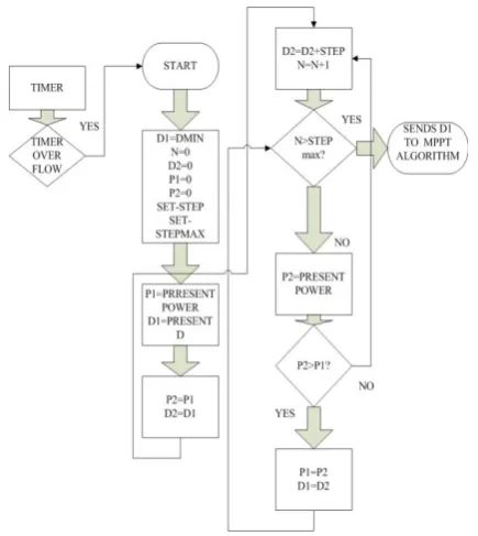
MPPT control is a control algorithm by which the Duty ratio is kept in a specific value and hence, the power extracted from the PV panel will be maximum. Power from the PV panel varies in accordance with solar irradiation, ambient condition and temperature. Similarly the electrical characteristics vary from the each solar cell. Incremental Conductance algorithm, P&O method, Hill climbing algorithm etc. are the important MPPT technique. During fast changing irradiance conditions and partial shading the incremental conductance algorithm is optimized MPPT in the suggested system. A portion of solar panel is shaded by any factors such as tree, building, and clouds etc. cause partial shading. As a result, a portion of PV panel is separated by shadow and more current will flows through the un-shaded portion. Therefore electrical characteristics of PV panel will be altered and causes damage to the PV panel. In order to avoid the shadow effect up to a limit, Incremental Conductance algorithm with D-sweep fig.3 (Duty ratio-sweep) is introduced [8]. Incremental conductance locates maximum power when the incremental conductance equal to the negative of instantaneous conductance. [9-13]
Fig. 3: D- sweep technique Flowchart
V. RESULTS
A 400V/300 W, solar PV system is used to verify the feasibility of multi –Solar power optimizer with MPPT results.
186 | P a g e
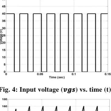
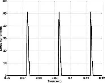
voltage is maintained to 400V.The above Simulink results are obtained as shown in below fig (4) which shows th e pulsating square input wave form of DC source. Fig (5), also inductor leakage current waveform shown in fig (6) and for (remaining) devices for capacitorcurrent& diode current is shown in fig (7). These results are obtained for the continuous current conduction mode of operation for high step up boost converter.
Fig. 4: Input voltage (
𝒗𝒈𝒔
) vs. time (t)
Fig. 5: Inductor leakage current (
𝑰𝒍𝒌
) v time
187 | P a g e
Fig. 7: For diode current (d1) vs. time (t)
Fig. 8: Efficiency of SPO
20 22 24 26 28 30 32 34 36 38 40
90 91 92 93 94 95 96 97 98 99 100
Voltage
E
f
f
ic
ie
n
c
y
Fig. 9: Efficiency with MPPT
188 | P a g e
The fig. 4-7 shows waveform of major components in CCM operation during one switching period. And the fig.8-9 shows the efficiency obtained by SPO &MPPT.Efficiency = OUTPUT/INPUT=38.6/40=97%.
VI. CONCLUSION
The high step-up SPO uses the coupled inductor with an appropriate turn’s ratio design and switched-capacitor technology to achieve a high-voltage gain that is 12.5 times higher than the input voltage. Because the leakage inductance energy of a coupled inductor is recycled and the voltage stress across the active switch S is constrained, the low RDS (ON) of active switch can be selected to improve maximum efficiency up to 96.7%. As a result, full load efficiency reaches 92.8%. The highest MPPT accuracy is 99.9% and the highest average accuracy is 97.9% at P PV = 150 W. A 300W SPO with a high step-up voltage gain and MPPT functions are implemented and verified.
REFERENCES
[1] Y. Fang and X. Ma, “A novel PV micro inverter with coupled inductors and double-boost topology,” IEEE
Trans. Power Electron., vol. 25, no. 12, pp. 3139–3147, Dec. 2010.
[2] A. Ch. Kyritsis, E. C. Tatakis, and N. P. Papanikolaou, “Optimum design of the current-source fly back inverter for decentralized grid-connected photovoltaic systems,” IEEE Trans. Energy Convers. , vol. 23, no. 1, pp. 281– 293, Mar. 2008.
[3] P. Tsao, “Simulation of PV systems with power optimizers and distributed power electronics,” in Proc. IEEE
Photovolt. Spec. Conf., Jun. 2010, pp. 389–393.
[4] D. D.-C. Lu and V. G. Agelidis, “Photovoltaic-battery-powered DC bus system for common portable electronic devices,” IEEE Trans. Power Electron, vol. 24, no. 3, pp. 849–855, Feb. 2009
[5] L. Zhang, K. Sun, Y. Xing, L. Feng, and H. Ge, “A modular grid-connected photovoltaic generation system based on DC bus,” IEEE Trans. Power Electron, vol. 26, no. 2, pp. 523–531, Feb. 2011.
[6]S.M.Chen,K.R.Hu,T.J.Liang,L.S.Yang,andY.H.Hsieh, “Implementation of high step-up solar power optimizer for DC micro grid application,” inProc. IEEE Appl. Power Electron Conf., Feb. 2012, pp. 28 [7] A.Pratt, P. Kumar, and T. V. Aldridge, “Evaluation of 400 V DC distribution in telco and data centers to
im-prove energy efficiency,” in Proc. IEEE Int. Telecommun. Energy Conf., Sep. /Oct. 2007, pp. 32–39.
[8]. M. Sokolov and D. Shmilovitz, “A Modified MPPT scheme for accelerated convergence,”IEEE Trans.
Energy Convers., vol.23, no.4, pp.1105-1107, Dec.2008.
[9].A. Ch. Kyritsis, E. C. Tatakis, and N. P. P apanikolaou, “Optimum design of the current -source fly back inverter for decentralized grid-connected photovoltaic systems,” IEEE Trans. Energy Convers. , vol. 23, no. 1, pp. 281– 293, Mar. 2008
[10].L. Zhang, K. Sun, Y. Xing, L. Feng, and H. Ge, “A modular grid -connected photovoltaic generation system based on DC bus,” IEEE Trans. Power Electron, vol. 26, no. 2, pp. 523–531, Feb. 2011.
189 | P a g e
Electron., vol.18.no.1.pp.65-73, jan.2003[12]. R.J .Wai, and R.Y .Duan,” High step up converter with coupled-inductor”IEEE Trans. Power
Electron., vol.20, no.5, pp.1025-1035, sep.2005.
[13]. S.M. Chen, T. J. Liang, L. S. Yang, and J. F. Chen, “A boost converter with capacitor multiplier and coupled inductor for AC module applications,” IEEE Trans. Ind. Electron, Early Access Articles, vol.
PP, no. 99, p. 1.)