Prepaid Energy Meter Using Microcontroller
K.Sathiyasekar, A.Abdul Bhagurudhin
1, T.Meyappan
2, S.Amarnath
3Department of Electrical and Electronics Engineering, S.A Engineering College, Chennai, India
ABSTRACT: In developing countries, the utilities are facing difficulties in electric bill in full scale. Therefore prepaid metering system is becoming popular for ensuring the collection of bill in advance. This project results an approach to automate the electricity billing system. A PIC Microcontroller based control section and co ordinates all the activities like reading the credit from the card through the card reading mechanism, computing and updating the net credit , displaying the credit on the LCD display. The Alarm (buzzer) introduces in the system is used to give the alert signal in the consume unit reaches final 5 units. As soon as the load unit reaches zero, the relay set up, which is interfaced between the AC main and load get tripped off.
KEYWORDS: Image processing, speech processing, emergency vehicle, Traffic density reduction.
I. INTRODUCTION
The trend of the time has always been in favor of that technology which finally becomes cost- effective as well as an elegant one. Traditional meter reading is done by the human operator, this require a more number of labor operator and long working hour to achieve the complete area data reading and billing. Due to the increase in the development of residential building and commercial building the meter reading task increases which require more number of human operator. In order to achieve efficient meter reading, reduce billing error and operation cost, automatic meter reading system play an important role. In present scenario the human operator goes to the consumer‟s house, takes the photography of meter reading and produces the bill. If the consumer is not available, the billing process will be pending and the human operator again needs to revisit the houses. Going to each and every consumer‟s house and generating the bill is a laborious task and requires lot of time. It becomes very difficult in rainy season. If any consumer didn‟t pay the bill the operator needs to go to their houses to disconnect the power supply. This has to be avoided and have to be controlled automatically. In postpaid system, there is no control use of electricity from the consumer‟s side. There is a lot of wastage of power in the consumer‟s side due to lack of planning of electrical consumption in an efficient way. In order to achieve efficient meter reading, reduce billing error and operation cost, automatic meter reading system play an important role. In present scenario the human operator goes to the consumer‟s house, takes the photography of meter reading and produce the bill. If the consumer is not available, the billing process will be pending and the human operator again needs to revisit the houses.
Going to each and every consumer‟s house and generating the bill is a laborious task and requires lot of time. It becomes very difficult in rainy season.
In this Project, series of energymeter, 16F877A microcontroller, global system for mobile communication (gsm), Sound sensor(buzzer),LED lights and c program software is used for coding and obtaining the output.
II. DETAILEDSTUDY
consumers according to their consumption. To automate the system of billing of energy is the main theme of this project. This will also help to avoid any tampering or break down of energy meter. On the other hand from the utility‟s point view, it is beneficial because they don‟t have to engage meter reading, bill preparation team and bill server. Most importantly utility receives the payment in three months earlier than usual time. No record keeping related to bills for the individual consumer is necessary for prepaid metering scheme and thus the related manpower also reduces. It also have a Global system for Mobile Communication (GSM) technology to monitor the power consumption and controlling of the meters remotely.
III. PROPOSED ARCHITECTURE
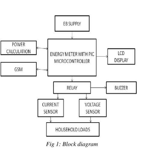
Fig 1: Block diagram
To develop a control method to control the energy meter automatically. If the consumer didn‟t pay the bill. The energy meter is controlled by the PIC Microcontroller. Here PIC Microcontroller based control section controls and co- ordinates all the activities like reading the credit from the card reading mechanism, computing and updating the net credit, displaying the net credit on the LCD Display. The design presents a Global System for Mobile Communication (GMS) technology to monitor the power consumption and controlling of the meter remotely. This system avoids the human intervention in power management. If the consumer didn‟t pay the bill in time, the user is informed through SMS system using GSM. If still user doesn‟t pay the bill then after the designed late consideration the power connection will be disconnected from the remote server automatically. Here PIC Microcontroller based control section controls and co- ordinates all the activities like reading the credit from the card reading mechanism, computing and updating the net credit, displaying the net credit on the LCD Display. The design presents a Global System for Mobile Communication (GMS) technology to monitor the power consumption and controlling of the meter remotely. Here PIC Microcontroller based control section controls and co- ordinates all the activities like reading the credit from the card reading mechanism, computing and updating the net credit, displaying the net credit on the LCD Display.
PIC MICROCONTROLLER
The main unit of the circuit is the PIC Microcontroller. PIC is a family of modified Harvard architecture microcontrollers made by microchip technology, derived from the PIC1650 originally developed by general instruments microelectronics division. The name PIC initially referred to Peripheral Interface Controller. Early models of PIC had read-only memory (ROM) or field-programmable EPROM for program storage, some with provision for erasing memory. All currents models use Flash memory for program storage, and newer models allow the PIC to program itself. Program memory and data memory are separated. Data memory is a 8-bit, 16-bit and in least models, 32-bit wide. Program instruction vary in bit count by family of PIC, and may be 12, 14, 16 or 24 bits long. . Early models of PIC had read-only memory (ROM) or field-programmable EPROM for program storage, some with provision for erasing memory. All currents models use Flash memory for program storage, and newer models allow the PIC to program itself. The main unit of the circuit is the PIC Microcontroller. PIC is a family of modified Harvard architecture microcontrollers made by microchip technology, derived from the PIC1650 originally developed by general instruments microelectronics division. The name PIC initially referred to Peripheral Interface Controller. Early models of PIC had read-only memory (ROM) or field-programmable EPROM for program storage, some with provision for erasing memory. All currents models use Flash memory for program storage, and newer models allow the PIC to program itself. Program memory and data memory are separated. Data memory is a 8-bit, 16- bit and in least models, 32-bit wide. On-Chip Memory refers to any memory (Code, RAM, or other) that physically exists on the Microcontroller itself. On-chip memory can be of several types, but we'll get into that shortly. External Code Memory is code (or program) memory that resides off-chip. This is often in the form of an external EPROM.
Diagram Of Chip Memory
External RAM is RAM memory that resides off-chip. This is often in the form of standard static RAM or flash RAM. The Microcontroller design consist of two parts
Hardware Software
ADVANTAGES:
• They are reliable and malfunctioning of PIC percentage is very less. • Performance is very fast because of using RISC architecture.
• Power conception is also very less when compared to other microcontrollers. • Programming is also very easy when compared to other microcontroller.
DISADVANTAGES:
PIN DIAGRAM OF PIC MICROCONTROLLER
Pin Diagram of PIC Microcontroller RELAY
The electromagnetic relay is connected interfaced between the AC mains and the load. As soon as the stored units are fully consumed the connection between the AC mains and the load gets tripped off. After recharging the relay gets energized and the supply is continuous. A relay is an electrically operated switch. Many relays use an electromagnet to mechanically operate a switch, but other operating principles are also used, such as solid-state relays. Relays are used where it is necessary to control a circuit by a low-power signal (with complete electrical isolation between control and controlled circuits), or where several circuits must be controlled by one signal. The first relays were used in long distance telegraph circuits as amplifiers: they repeated the signal coming in from one circuit and re-transmitted it on another circuit. Relays were used extensively in telephone exchanges and early computers to perform logical operations.
Diagram Of Relay
When the stored charge in the SIM IC reaches five units, the buzzer produces a beep sound, which is an alert indication to recharge the SIM IC. A buzzer or beeper is an audio signaling device, which may be mechanical, electromechanical, or piezoelectric. Typical uses of buzzers and beeper include alarm devices, times and confirmation of user input such as
a mouse click or keystroke.
Diagram of Buzzer
A buzzer takes some sort of input and emits a sound in response to it. They may use various means to produce the sound; everything from metal clappers to electromechanical devices. A buzzer needs to have some way of taking in energy and converting it to acoustic energy. Many buzzers are part of a larger circuit and take their power directly from the device‟s power source. In other cases, however, the buzzer may be battery powered so that it will go off in the event of a mains outage. A buzzer takes some sort of input and emits a sound in response to it. They may use various
means to produce the sound; everything from metal clappers to electromechanical devices.
Circuit Diagram of Buzzer LIQUID CRYSTAL DISPLAY
words, digits, and 7-segment displays. They use the same basic technology, except that arbitrary images are made up of a large number of small pixels, while other displays have larger elements. LCDs are used in a wide range of applications including computer monitors, televisions, instrument panels, aircraft cockpit displays, and signage. They are common in consumer devices such as DVD players, gaming devices, clocks, watches, calculators, and telephones, and have replaced cathode ray tube (CRT) displays in nearly all applications. They are available in a wider range of screen sizes than CRT and plasma displays, and since they do not use phosphors, they do not suffer image burn-in. LCDs are, however, susceptible to image persistence.
Diagram Of LCD
GLOBAL SYSTEM FOR MOBILE COMMUNICATION
Diagram Of GSM ENERGY METER
Electric meter or watt-hour meter, a device that measure the quantity of electric energy. One kilowatt hour is the quantity of electric energy needed to supply of electricity for a span of one hour. An electrical power business uses electric meters to quantify the number of electricity consumed by each. An electricity meter, electric meter, electrical meter, or energy meter is a device that measures the amount of electric energy consumed by a residence, a business, or an electrically powered device. Electric utilities use electric meters installed at customers' premises to measure electric energy delivered to their customers for billing purposes. They are typically calibrated in billing units, the most common
one being the kilowatt hour. They are usually read once each billing period. When energy savings during certain periods are desired, some meters may measure demand, the maximum use of power in some interval. "Time of day" metering allows electric rates to be changed during a day, to record usage during peak high-cost periods and off-peak,
lower-cost, periods. Also, in some areas meters have relays for demand response load shedding during peak load periods. One kilowatt hour is the quantity of electric energy needed to supply of electricity for a span of one hour. An
electrical power business uses electric meters to quantify the number of electricity consumed by each. An electricity meter, electric meter, electrical meter, or energy meter is a device that measures the amount of electric energy
consumed by a residence, a business, or an electrically powered device.
Diagram of Energy Meter
One kilowatt hour is the quantity of electric energy needed to supply of electricity for a span of one hour. An electrical power business uses electric meters to quantify the number of electricity consumed by each. An electricity meter, electric meter, electrical meter, or energy meter is a device that measures the amount of electric energy consumed by a residence, a business, or an electrically powered device. An electrical power business uses electric meters to quantify the number of electricity consumed by each. An electricity meter, electric meter, electrical meter, or energy meter is a device that measures the amount of electric energy.
IV. LITERATURE REVIEW Article [1]
Das v.v., “Wireless Communication system for Energy Meter Reading”, (2011).
Energy meter reading is a tedious and an expensive affair. The meter reading has to go and take the reading manually to issues the bill, which will later be entered in the software to automate the billing and payment system. It would have reduced the laborious task and financial wastage if can automate the manual meter reading process. This paper proposes a new network communication system for energy meter reading by integrating communication technology and software system along with the existing meters. A wireless or wired communication system will be integrated with electronic energy meter to have remote access over the usage of electricity. Even though there are two different modules, energy meter delivers the reading details as on when it demands by the communication system.
The communication system further connected with the electricity regional/sub-regional office, which will rather act as a base station. Instead of creating a separate communication system and backbone.
Article [2]
“Design and Implementation of a Zig Bee-Based Wireless Automatic Meter Reading System” (2012).
IBM, Ember, Mitsubishi, Motorola, and Philips, etc.. Many semiconductor companies are targeting the ZigBee market. Since the standards were launched not long ago, chips in line with protocol have been available of multi- chip solution and single- chip solution. It can be expected that ZigBee will have comprehensive applications in the field of automation. The main methods of metering at home and abroad are: manual meter reading, IC Card prepaid meter, wire-line and wireless meter reading system. Manual meter reading has been for decades, but with the implementation of one home one meter, drawbacks of this method of reading are more and more, like difficult entrance to home, low efficiency of fee settlement, etc. Its main application areas include industrial controls, consumer electronics, car automation, agricultural automation, and medical equipment control.
Article [3]
“Automatic Electric Meter Reading System: A Cost-Feasible Alternative Approach in Meter Reading For Bangladesh Perspective Using Low-Cost Digital Wattmeter and Wimax Technology” (2013).
Energy meter reading is a monotonous and an expensive task. Now the meter reader people goes to each meter and take the meter reading manually to issue the bill which will later be entered in the billing software for billing and payment automation. If the manual meter reading and bill data entry process can be automated then it would reduce the laborious task and financial wastage. “Automatic Electric Meter Reading (AMR) System” is a metering system that is to be used for data collecting from the meter and processing the collected data for billing and other decision purposes. In this paper we have proposed an automatic meter reading system which is low cost, high performance, highest data rate, highest coverage area and most appropriate for Bangladesh perspective. In this AMR system there are four basic units. They are reading unit, communication unit, data receiving and processing unit and billing system. For reading unit we identified the disk rotation of the energy meter and stored the data in microcontroller. So it is not required to change the current analogy energy meter. An external module will be added with the current energy meter. In the communication unit, Wimax transceiver was used for wireless communication between meter end and the server end because of its wide coverage area. In the data receiving and processing unit meter reading will be collected from the transceiver which is controlled by another microcontroller. There will be a computer application that will take the data from the microcontroller. This will also help to avoid any tampering or break down of energy meter. There are various AMR system exists all over the world. Those systems were analyzed and we found they are not feasible for Bangladesh. Our proposed system is completely new and is appropriate for Bangladesh perspective. Automatic Meter Reading System (AMR) is the remote collection of consumption data from customer utility like Electric meters using radio frequency, telephony, power-line or satellite communications technologies and process the data to generate the bill. In the data receiving and processing unit meter reading will be collected from the transceiver which is controlled by another microcontroller. There will be a computer application that will take the data from the microcontroller.
Article [4]
“Automated Wireless Meter Reading System for Monitoring and Controlling Power Consumption” (2014).
operator goes to the consumer‟s house and produces the bill as per the meter reading. If the consumer is not available, the billing process will be pending and human operator again needs to revisit.
Article [5]
“Arm Based Wireless Energy Meter Reading System Along With Power On/Off Circuit” (2015).
In this paper we discuss about wireless energy meter reading system along with power on/off circuit. It is a simple system which is used for measuring electrical bills through wireless communication and sends the information regarding consumed power & also send the dead line for paying of electrical bill and the system also having the power on/off circuit used to disconnect the power supply to energy meter by using wireless technology when the consumer fail to pay the electrical bill. Disconnecting the power supply through proper selection of switch located at the control unit. System also sends an acknowledgement to consumer regarding status of the system. Wireless energy meter reading system developed with ARM7 Processor, wireless communication network and other peripheral circuits. With the rapid developments in the Wireless communication technology by the use of microcontrollers, there are many improvements in automating various industrial aspects for reducing manual efforts. The traditional manual Meter Reading was not suitable for longer operating purposes as it spends much human and material Resource. It brings additional problems in calculation of readings and billing manually. It became a hard task in handling and maintaining the power as per the growing requirements. Presently maintenance of the power is also an important task as the human
operator goes to the consumer‟s house and produces the bill as per the meter reading. If the consumer is not available, the billing process will be pending and human operator again needs to revisit. Going to
each and every consumer‟s house and generating the bill is a laborious task and requires lot of time. It becomes very difficult especially in rainy season. If any consumer did not pay the bill, the operator needs to go to their houses to disconnect the power supply. These processes are time consuming and difficult to handle.
Article [6]:
“Design of remote automatic meter reading system based on ZigBee and GPRS” (2010).
With the development of the computer, wireless communications and the rapid development of microelectronics technology, the people‟s life standard is constantly enhancing. And the demand of the home automation, building automation is also increasing. For households at the top of high buildings and luxury housing plot, the traditional meter reading has been unable to meet the future residential development needs, traditional metering not only waste labour human power, but also exit man-made meter error. If there is always no body at home, and charging are even more difficult. Smart increasing demands for remote meter reading. Using remote, wireless meter reading system can avoid manual meter reading mistakes, and errors of leakage of metering reading. It can improve efficiency, reduce labour intensity, and liberate labour, force. To meet demand, this paper will make the use of the ZigBee and GPRS technology to design a system that automatically copied in distance.
Article 7:
“Designing and Control Mechanism of ZigBee based Automatic Meter Reading” (2013).
V. CONCLUSION
Thus in this paper the PIC control section controls and co- ordinates all the activities of the energy meter, which is designed to continuously monitor the energy meter reading and to disconnect the power connection remotely whenever fails to pay the bill after warning period is lapsed and power reconnect after bill payments. It avoids the human intervention, provides efficient meter reading, avoid the billing error and reduce the maintenance cost. It display the corresponding information on LCD for user notification. The generated bill can also be sent to the consumer by GSM. Thus the complete process of monitoring of energy meter, bill calculation, notification of due date, meter disconnection or reconnection can be automated efficiently with better performance and less manpower.
VI. FUTURE SCOPE
This project is designed with constraint of time and cost. This can be developed with following facility, This project can be modified to send the information regarding the balance charge operating condition etc. The system can be interfaced with the sensors to check different types of meter tampering and fault conditions. This controller can have one embedded power factor controller to correct the power factor.
In this project the data communication is through a mobile network which is little bit expensive media but it can be modified to communicate through Ethernet communication using TCP/IP protocols.
In this project an electromagnetic meter is being used for reading the energy consumption. We can replace the electromagnetic meter by an electronic meter unit.
REFERENCES
[1] Das v.v, "Wireless Communication System for Energy Meter Reading", International Conferences on Advances in Recent Technologies in Communication V and Computing, pp. 896-898,(2012).
[2] Tanvir Ahmed, Md Suzan Miah, Md. Manirul Islam and Md. RakibUddin, "Automatic Electric Meter Reading System: A Cost-Feasible Alternative Approach In Meter Reading For Bangladesh Perspective Using Low-Cost Digital Wattmeter AndWimax Technology", International Journal Eng. Tech, pp. 800-807, (2011).
[3] Liting Cao, Jingwen Tian and Dahang Zhang, "Networked Remote Meter-Reading System Based on Wireless Communication Technology", International Conference on Information Acquisition, IEEE,(2013).
[4] Li Xiaoguang Hu, "Design of an ARM-Based Power Meter Having WIFI Wireless Communication Module", IEEE, (2009).
[5] Rodney Tan H.G,C.H. Lee and V.H. Mok, "Automatic Power Meter Reading system using GSM Network", The 8th International Power Engineering Conference, pp. 465- 469, (2009).
[6] Li Quan-Xi and Li Gang, "Design of Remote Automatic Meter Reading System based on Zigbee and GPRS", Proceedings of the Third International Symposium on Computer Science and Computational Technology (ISCSCT '10), pp. 186-189,(2009).
[7] Boyina S. Rao and Gnanasekaranathan .B, “Domestic Prepaid Distribution System”, International Journal of Advanced Engineering Technology (IJAET) Vol.3, Issue 2, 2012.
[8] Nagaraju Kommu, Pammi. Nagamani and Manoj Kollam, "Designing of Automated Power meter reading Zigbee Communication", International Journal of Computer & Communication Technology, (2011).
[9] Shaik Meeravali, S Nagireddi and S Rajitha, "Designing and Control Mechanism of Zigbee based Automatic Meter Reading", International Journal of Engineering Research & Technology (IJERT), vol. 1, no. 7, pp. 2278-0181, (2012).