Performance Comparisons of MIMO Techniques
with Application to WCDMA Systems
Chuxiang Li
Department of Electrical Engineering, Columbia University, New York, NY 10027, USA Email:[email protected]
Xiaodong Wang
Department of Electrical Engineering, Columbia University, New York, NY 10027, USA Email:[email protected]
Received 11 December 2002; Revised 1 August 2003
Multiple-input multiple-output (MIMO) communication techniques have received great attention and gained significant devel-opment in recent years. In this paper, we analyze and compare the performances of different MIMO techniques. In particular, we compare the performance of three MIMO methods, namely, BLAST, STBC, and linear precoding/decoding. We provide both an analytical performance analysis in terms of the average receiver SNR and simulation results in terms of the BER. Moreover, the applications of MIMO techniques in WCDMA systems are also considered in this study. Specifically, a subspace tracking algo-rithm and a quantized feedback scheme are introduced into the system to simplify implementation of the beamforming scheme. It is seen that the BLAST scheme can achieve the best performance in the high data rate transmission scenario; the beamforming scheme has better performance than the STBC strategies in the diversity transmission scenario; and the beamforming scheme can be effectively realized in WCDMA systems employing the subspace tracking and the quantized feedback approach.
Keywords and phrases:BLAST, space-time block coding, linear precoding/decoding, subspace tracking, WCDMA.
1. INTRODUCTION
Multiple-input multiple-output (MIMO) communication technology has received significant recent attention due to the rapid development of high-speed broadband wireless communication systems employing multiple transmit and receive antennas [1,2,3]. Many MIMO techniques have been proposed in the literature targeting at different scenarios in wireless communications. The BLAST system is a layered space-time architecture originally proposed by Bell Labs to achieve high data rate wireless transmissions [4,5,6]. Note that the BLAST systems do not require the channel knowl-edge at the transmitter end. On the other hand, for some ap-plications, the channel knowledge is available at the trans-mitter, at least partially. For example, an estimate of the channel at the receiver can be fed back to the transmitter in both frequency division duplex (FDD) and time division duplex (TDD) systems, or the channel can be estimated di-rectly by the transmitter during its receiving mode in TDD systems. Accordingly, several channel-dependent signal pro-cessing schemes have been proposed for such scenarios, for example, linear precoding/decoding [7]. The linear precod-ing/decoding schemes achieve performance gains by
allocat-ing power and/or rate over multiple transmit antennas, with partially or perfectly known channel state information [7]. Another family of MIMO techniques aims at reliable trans-missions in terms of achieving the full diversity promised by the multiple transmit and receive antennas. Space-time block coding (STBC) is one of such techniques based on orthog-onal design that admits simple linear maximum likelihood (ML) decoding [8,9,10]. The trade-offbetween diversity and multiplexing gain are addressed in [11,12], which are from a signal processing perspective and from an information theo-retic perspective, respectively.
Some simple MIMO techniques have already been pro-posed to be employed in the third-generation (3G) wireless systems [13,14]. For example, in the 3GPP WCDMA stan-dard, there are open-loop and closed-loop transmit diver-sity options [15,16]. As more powerful MIMO techniques emerge, they will certainly be considered as enabling tech-niques for future high-speed wireless systems (i.e., 4G and beyond).
compare the performance of three MIMO schemes, namely, BLAST, STBC, and linear precoding/decoding. Note that both BLAST and STBC do not require channel knowledge at the transmitter, whereas linear precoding/decoding does. For each of these cases, we provide an analytical performance analysis in terms of the receiver output average signal-to-noise ratio (SNR) as well as simulation results on their BER performance. Moreover, we also consider the application of these MIMO techniques in WCDMA systems with multipath fading channel. In particular, when precoding is used, a sub-space tracking algorithm is needed to track the eigensub-space of the MIMO system at the receiver and feed back this infor-mation to the transmitter [17,18,19,20]. Since the feedback channel typically has a very low bandwidth [21], we contrive an efficient and effective quantized feedback approach.
The main findings of this study are as follows.
(i) In the high data rate transmission scenario, for exam-ple, four symbols per transmission over four transmit antennas, the BLAST system actually achieves a bet-ter performance than the linear precoding/decoding schemes, even though linear precoding/decoding make use of the channel state information at the trans-mitter.
(ii) In the diversity transmission scenario, for example, one symbol per transmission over two or four trans-mit antennas, beamforming offers better performance than the STBC schemes. Hence the channel knowledge at the transmitter helps when there is some degree of freedom to choose the eigen channels.
(iii) By employing the subspace tracking technique with an efficient quantized feedback approach, the beamform-ing scheme can be effective and feasible to be employed in WCDMA systems to realize reliable data transmis-sions.
The remainder of this paper is organized as follows. In Section 2, performance analysis and comparisons of diff er-ent MIMO techniques are given for the narrowband scenario. Section 3describes the WCDMA system based on the 3GPP standard, the channel estimation method, the algorithm of tracking the MIMO eigen-subspace, as well as the quantized feedback approach. Simulation results and further discus-sions are given in Section 4.Section 5contains the conclu-sions.
2. PERFORMANCE ANALYSIS AND COMPARISONS OF MIMO TECHNIQUES
In this section, we analyze the performance of several MIMO schemes under different transmission rate assumptions, for the cases of two and four transmit antennas. BLAST and lin-ear precoding/decoding schemes are studied and compared for high-rate transmissions in Section 2.1. Section 2.2 fo-cuses on the diversity transmission scenario, where different STBC strategies are investigated and compared with beam-forming and some linear precoding/decoding approaches.
2.1. BLAST versus linear precoding for high-rate transmission
Assume that there arenT transmit andnR receive antennas, wherenR ≥nT. In this section, we assume that the MIMO
system is employed to achieve the highest data rate, that is, nT symbols per transmission. When the channel is unknown
to the transmitter, the BLAST system can be used to achieve this; whereas when the channel is known to the transmitter, the linear precoding/decoding can be used to achieve this.
2.1.1. BLAST
In the BLAST system, at each transmission, nT data sym-bolss1,s2,. . .,snT,si∈A, whereAis some unit-energy (i.e.,
E{|si|2} =1) constellation signal set (e.g., PSK, QAM), are
transmitted simultaneously from all nT antennas. The re-ceived signal can be represented by
where yi denotes the received signal at the ith receive an-tenna;hi,jdenotes the complex channel gain between theith
receive antenna and the jth transmit antenna;ρdenotes the total transmit SNR; andn∼Nc(0,InR).
The received signal is first matched filtered to obtainz= HHy = ρ/nTHHHs+HHn. DenoteΩ HHH andw
HHn, and thus,w∼Nc(0,Ω). The matched-filter output is
then whitened to get
u=Ω−1/2z=
ods can be used to detect the symbol vectors. For example, the ML detection rule is given by
ˆ
which has a computational complexity exponential in the number of transmit antennas nT. On the other hand, the sphere decoding algorithm offers a near-optimal solution to (2) with an expected complexity of O(n3T) [22]. More-over, a linear detector makes a symbol-by-symbol decision ˆ
the above-mentioned BLAST decoding algorithms, the lin-ear zero-forcing detector has the worst performance. The de-cision statistics of this method is given by
x=Gu=Ω−1/2u=
ρ nTs+Ω
−1/2˜v. (4)
It follows from (4) that the received SNR for symbol sj is (ρ/nT)/[Ω−1]j,j,j=1, 2,. . .,nT. Hence the average received
SNR under linear zero-forcing BLAST detection is given by
SNRBLAST-LZF=ρ
1 n2
T nT
j=1 1
Ω−1
j,j
. (5)
2.1.2. Linear precoding and decoding
When the channelHis known to the transmitter, a linear pre-coder can be employed at the transmitter and a correspond-ing linear decoder can be used at the receiver [7]. Specifically, supposem≤nTsymbolss=[s1 s2 · · · sm]Tare transmit-ted per transmission, wherem =rank(H). Then the linear precoder is annT×mmatrixFsuch that the transmitted sig-nal isFs. ThenR×1 received signal vector is then
y=HFs+n, (6)
wheren ∼Nc(0,InR). At the receiver,yis first matched
fil-tered, and then anm×nT linear decoderGis applied to the
matched-filter output to obtain the decision statistics
x=GHHy=GΩFs+GHHn. (7)
The linear precoderFand decoderGare chosen to minimize a weighted combination of symbol estimation errors, that is, minF,GE{D1/2(s−x)2}, whereDis a diagonal positive
def-inite matrix subject to the total transmitter power constraint tr(FFH)≤ρ. The weight matrixDis such that all decoded symbols have equal errors (equal error design). Denote the eigendecomposition ofΩasΩ=VΛVH+ ˜VΛ˜V˜H, whereΛ andVcontain themlargest eigenvalues and the correspond-ing eigenvectors ofΩ, respectively; and ˜Λand ˜Vcontain the remaining (nT−m) eigenvalues and the corresponding eigen-vectors, respectively. Denoteγ =ρ/tr(Λ−1). Then the linear precoder and decoder are given by [7]
F=γ1/2VΛ−1/2,
G=γ−1/21 +γ1/2Λ
−1/2VH. (8)
It can be verified that GHHHF = (1/(γ−1+γ))Im. Hence this precoding scheme transforms the MIMO channel into a scaled identity matrix. Furthermore, the received SNRs for all decoded symbols are equal, given byγ, that is,
SNRequal-error precoding= ρ trΛ−1 =
ρ
trΩ−1. (9)
Remark1. The BLAST system can be viewed as a special case of linear precoding with the transmitter filterF=ρ/nTInT.
And the zero-forcing BLAST detection scheme corresponds to choosing the receiver filterG=Ω1/2.
Remark2. An alternative precoding scheme is to chooseF=
ρ/nTVandG=VH. Then the output of the linear decoder can be written as
x=
ρ nTV
HHHHVs+VHHHn=
ρ
nTΛs+w, (10)
where w ∼ Nc(0,Λ). Hence this scheme also transforms
the MIMO channel into a set of independent channels, but with different SNRs. The received SNR for the jth symbol is (ρ/nT)λj, whereλj is the jth eigenvalue contained by Λ. We call this method the whitening precoding. The average received SNR is given by
SNRwhitening precoding=ρ
1 n2
T nT
j=1 λj
=ρtr(nΩ2)
T
. (11)
Note that the whitening precoding is different from the equal-error precoding in (8). In particular, different received SNRs are achieved over different subchannels for the whiten-ing precodwhiten-ing, whereas the equal-error precodwhiten-ing provides the same SNR over all subchannels.
2.1.3. Comparisons
We have the following result on the relative SNR perfor-mance of the BLAST system and the two precoding schemes discussed above.
Proposition 1. Suppose that annT×nRMIMO system is em-ployed to transmit nT symbols per transmission, using either the BLAST system, the equal-error precoding scheme, or the whitening precoding scheme, then
SNRwhitening precoding≥SNRBLAST-LZF ≥SNRequal-error precoding.
(12)
Proof. We first show that
SNRBLAST-LZF≥SNRequal-error precoding. (13)
Since
1 nT
nT
j=1 λ−1
j = n1 T
nT
j=1
Ω−1
j,j≥
nT
nT
j=1
1/Ω−1j,j, (14) we have
1 n2
T nT
j=1 1
Ω−1
j,j
≥nT1
j=1λ−1j . (15)
We next show that SNRBLAST-LZF ≤SNRwhitening precoding. First, we have the following.
Fact1. Suppose thatAis an×npositive definite matrix, then 1
A−1
i,i
=Ai,i−˜aiHA˜−1i ˜ai, (16)
where ˜Ai is the (n−1)×(n−1) matrix obtained fromA by removing the ith row andith column; and ˜ai is the ith column ofAwith theith entryAi,iremoved. Note that ˜Aiis
a principal submatrix ofA; sinceAis positive definite, so is, ˜
Ai, and ˜A−1i exists. To see (16), denote the above-mentioned partitioning of the Hermitian matrixAwith respect to the ith column and row byA=( ˜Ai, ˜ai,Ai,i). In the same way, we partition its inverseB A−1 =( ˜Bi, ˜bi,Bi,i). Now from the fact thatAB=In, it follows that
Ai,iBi,i+ ˜aHi b˜i=1, a˜iBi,i+ ˜Aib˜i=0. (17)
Solving forBi,ifrom (17), we obtain (16).
Using (16), we have
nT
j=1 1
Ω−1
j,j =
nT
j=1
Ωi,i−ω˜Hi Ω˜−1i ω˜i≤ nT
j=1
Ωi,i=tr(Ω).
(18)
It then follows from (5), (11), and (18) that SNRBLAST-LZF ≤ SNRwhitening precoding.
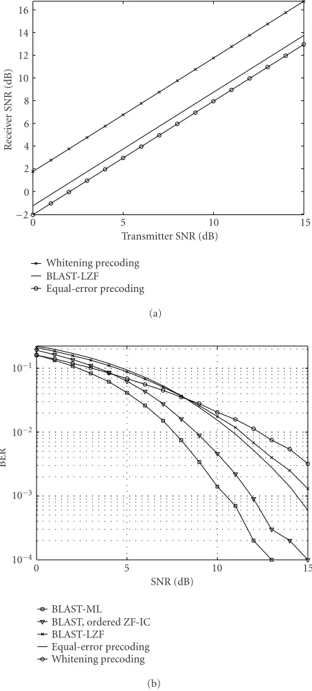
Figure 1shows the comparisons between the BLAST and the linear precoding/decoding schemes in terms of the aver-age receiver SNR as well as the BER for a system withnT =4 andnR =6. The rate is four symbols per transmission. The SNR curves in Figure 1a are plotted according to (9), (5), and (11). It is seen that the SNR curves confirm the conclu-sion ofProposition 1. Moreover, it is interesting to see that the SNR ordering given by (12) does not translate into the corresponding BER order. This can be roughly explained as follows. The BER for theith symbol stream can be approx-imated asQ(γ√SNRi), whereγis a constant determined by the modulation scheme. The average BER is then
p∼=n1
T nT
i=1
QγSNRi
. (19)
SinceQ(·) is a concave function, we have
p≤QγSNR
. (20)
Hence, the average SNR value does not directly translate into the average BER. Moreover, it is seen from theFigure 1bin Figure 1that the interference cancellation with ordering [6] BLAST detection method offers a significant performance gain over the linear zero-forcing method, making the BLAST outperform the precoding schemes by a substantial margin.
15 10
5 0
Transmitter SNR (dB)
−2 0 2 4 6 8 10 12 14 16
R
ec
ei
ver
SNR
(dB)
Whitening precoding BLAST-LZF Equal-error precoding
(a)
15 10
5 0
SNR (dB) 10−4
10−3 10−2 10−1
BER
BLAST-ML
BLAST, ordered ZF-IC BLAST-LZF
Equal-error precoding Whitening precoding
(b)
Figure1: Comparisons of the average receiver SNR and the BER between the BLAST and the linear precoding/decoding schemes:
nT=4 andnR=6; the rate is four symbols/transmission.
2.2. Space-time block coding versus beamforming for diversity transmission
antennas, a maximum diversity order of nTnR is possible when the transmission rate is one symbol per transmission. When the channel is unknown at the transmitter, this can be achieved using STBC (fornT =2); and when the channel is known at the transmitter, this can be achieved using beam-forming.
2.2.1. Two transmit antennas case
Alamouti scheme
WhennT =2, the elegant Alamouti transmission scheme can be used to achieve full diversity transmission at one symbol per transmission [8]. It transmits two symbolss1ands2over two consecutive transmissions as follows. During the first transmission,s1ands2are transmitted simultaneously from antennas 1 and 2, respectively; during the second transmis-sion,−s∗2 ands∗1 are transmitted simultaneously from trans-mit antennas 1 and 2, respectively. The received signals at re-ceive antennaicorresponding to these two transmissions are given by
Note that (21) can be rewritten as follows:
At each receive antenna, the received signal is matched filtered to obtain
zi=H˜H symbol slicing operation, and
z=
The received SNR is therefore given by
SNRAlamouti= (ρ/2)
Beamforming can be referred to as maximum ratio weighting [23], and it is a special case of the linear precoding/decoding discussed inSection 2.1.2, where
F=ρv1, G=v1H,
(27)
andv1is the eigenvector corresponding to the largest eigen-value ofΩ. Hence in the beamforming scheme, at each trans-mission, the transmitter transmitsv1sfrom all transmit an-tennas, wheresis a data symbol. The received signal is given by
. The received SNR in this case is
SNRbeamforming=ρλ1. (29)
Comparing (25) with (29), it is obvious that SNRbeamforming≥ SNRAlamouti. Note that in this case, the SNR order indeed translates into the BER order; since in the Alamouti scheme, both symbols have the same SNR, then
pbeamforming=Q
2.2.2. Four transmit antennas case One symbol per transmission
It is known that rate-one orthogonal STBC only exists for nT =2, that is, the Alamouti code. For the case of four trans-mit antennas (nT =4), we adopt a rate-one (almost orthog-onal) transmission scheme with the following transmission matrix:
transmissions are given by
The matched-filter output at theith receive antenna is given by pairs, we can write
tems and they can be decoded using either linear detection or ML detection. For example, the linear decision rule is given by ˆs =Q[ni=1R Gi,zi,], =1, 2, where the linear detector can be either a zero-forcing detector, that is,Gi,=Γ−1i , or an MMSE detector, that is,Gi,=(Γi+ (4/ρ)I2)−1. On the other
hand, the ML detection rule is given by
ˆ
When the channel state is known at the transmitter, the optimal transmission method to achieve one symbol per transmission is the beamforming scheme described by (27), (28), and (29).
Note that the received SNR of the above block coding scheme with linear zero-forcing detector is given by
SNR=ρ
whereas the SNR of the beamforming scheme is given by SNRbeamforming=ρλ1.
Two symbols per transmission
Now suppose that a rate of two symbols per transmission is desired using four transmit antennas. When the channel is unknown at the transmitter, we can use one pair of the trans-mit antennas to transtrans-mits1 =[s1 s2]T using the Alamouti scheme, and use the other pair to transmits2=[s3 s4]Talso using Alamouti scheme. In this way, we transmit four sym-bols over two transmissions. At theith receive antenna, the received signalyi=[yi(1) yi(2)]Tcorresponding to the two transmissions is given by
yi=
. Therefore, we have
The received signalyis first matched filtered to obtain
z=H˜Hy=ρ
Then the output of the whitening filter is given by u = ˜
Ω−1/2
z=ρ/2 ˜Ω1/2s+w, wherew∼Nc(0,I4). Now we can use any of the aforementioned BLAST decoding methods to decodes.
12 10 8
6 4 2 0
SNR (dB) 10−6
10−5 10−4 10−3 10−2 10−1
BER
Beamforming: 2 trans. ant., 3 recv. ant. Alamouti: 2 trans. ant., 3 recv. ant. Beamforming: 4 trans. ant., 6 recv. ant. STBC (ML): 4 trans. ant., 6 recv. ant. STBC (LZF): 4 trans. ant., 6 recv. ant.
Figure 2: Comparisons of the BER performances among the MIMO techniques for one symbol/transmission: beamforming ver-sus Alamouti withnT=2 andnR=3; beamforming versus rate-one
STBC withnT=4 andnR=6.
ρ/(λ−11 +λ−12 ). The whitening precoding method, on the other hand, is specified byF=ρ/2[v1v2] andG=[v1v2]H; and the average received SNR of this method is given by SNRwhitening precoding=ρ((λ1+λ2)/4). Note thatλ1andλ2are the two largest eigenvalues contained inΛ.
2.2.3. Comparisons
Figure 2 shows the performance comparisons among the MIMO techniques to achieve one symbol per transmission. Specifically, the beamforming scheme is compared with the Alamouti code for a system with two transmit antennas, and the beamforming scheme is compared with the rate-one STBC for a system with four transmit antennas. It is observed fromFigure 2that the beamforming scheme achieves about 2 dB gain over the Alamouti code, and similarly, the beam-forming can achieve much better performance than the rate-one STBC strategy.
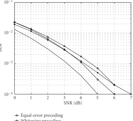
Figure 3 shows the performance comparisons between the linear precoding/decoding schemes and the rate-two STBC strategy for a system withnT=4 andnR=6 to achieve two symbols per transmission. It is seen from Figure 3that the rate-two STBC achieves a better performance than the linear precoding/decoding schemes, and the performance gap is not so large. In particular, the rate-two STBC with BLAST-LZF decoding has an approximate performance to the equal-error precoding scheme.
It is observed from Figures 1 and3 that although the linear precoding/decoding schemes exploit the channel knowledge at the transmitter, they may not have perfor-mance gains compared to those MIMO techniques
with-7 6 5 4 3 2 1 0
SNR (dB) 10−4
10−3 10−2 10−1
BER
Equal-error precoding Whitening precoding Rate-2 STBC, BLAST-LZF Rate-2 STBC, BLAST-ML
Figure3: Comparisons of the BER performances between the linear precoding/decoding strategies and the rate-two STBC:nT =4 and
nR=6; the rate is two symbols/transmission.
out channel knowledge requirement at the transmitter. And this phenomenon is evident especially in the high-data rate transmission scenario, that is, BLAST versus linear precod-ing/decoding schemes withnT =4. This can be explained as follows. Note that, for the linear precoding/decoding strate-gies discussed above, the adaptive modulation is not em-ployed, and thus, the performance gain is limited for the fixed modulation.
3. WCDMA DOWNLINK SYSTEMS
In this section, a WCDMA downlink system based on the 3GPP standard, a subspace tracking algorithm, as well as a quantized feedback approach are specified. In Section 3.1, we describe the WCDMA system, including the structures of the transmitter and the receiver, the channelization and scrambling codes, the frame structures of the data and the pilot channels, the multipath fading channel model, as well as the channel estimation algorithm. InSection 3.2, we de-tail the subspace tracking method and the quantized feed-back scheme.
3.1. System description
3.1.1. Transmitter and receiver structures
The system model of the downlink WCDMA system is shown inFigure 4. The left part ofFigure 4is the transmitter struc-ture. The data sequences of the users are first spread by unique orthogonal variable spreading factor (OVSF) codes (Cch,SF,1, Cch,SF,2,. . .), and then, the spread chip sequences
Decoding r11
r12 . . . r1L
Finger tracking for data
Channel estimator r11
r12 . . . r1L
Finger tracking for pilot Sum
Sum X X
Csc,0 Cch,SF,0 Pilot
X X
Csc,0 Cch,SF,0
Pilot
Sum Csc,2
Cch,SF,2
User 2
Csc,1 Cch,SF,1
User
1 X X
X X . . .
. . .
. . .
Figure4: Transmitter and receiver structures of the downlink WCDMA system.
sequences from different users, the data sequences are com-bined with the pilot sequence, which is also spread and scrambled by the codes (Cch,SF,0,Ccs,0) for the pilot
chan-nel sent to each antenna. The specifications of OVSF and scrambling codes can be referred to [15]. The right part of Figure 4shows the receiver structure of this system with one receive antenna. We assume the number of multipaths in the WCDMA channel isL. Each receive antenna is followed by a bank of RAKE fingers. Each finger tracks the correspond-ing multipath component for the receiver antenna and per-forms descrambling and despreading for each of theL mul-tipath components. Such a receiver structure is similar to the conventional RAKE receiver but without maximal ratio combining (MRC). Hence, there areLoutputs for each re-ceive antenna, and thus, each of theLantenna outputs can be viewed as avirtualreceive antenna [14]. With the received pilot signals, the downlink channel is estimated accordingly. This channel estimate is provided to the detector to perform demodulation of the received users’ signals.
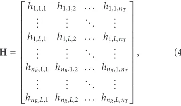
It is shown in [14] that the above receiver scheme with virtual antennas essentially provides an interface between MIMO techniques and a WCDMA system. The outputs of the RAKE fingers are sent to a MIMO demodulator that op-erates at the symbol rate. The equivalent symbol-rate MIMO channel response matrix is given by
H=
h1,1,1 h1,1,2 . . . h1,1,nT
..
. ... . .. ... h1,L,1 h1,L,2 . . . h1,L,nT
..
. ... . .. ... hnR,1,1 hnR,1,2 . . . hnR,1,nT
..
. ... . .. ... hnR,L,1 hnR,L,2 . . . hnR,L,nT
, (43)
wherehi,l,jdenotes the complex channel gain between thejth transmit antenna and thelth finger of theith receive antenna. Hence (43) is equivalent to a MIMO system withnTtransmit antennas and (nR·L) receive antennas [14].
3.1.2. Multipath fading channel model and channel estimation
Each user’s channel contains four paths, that is,L=4. The channel multipath profile is chosen according to the 3GPP specifications. That is, the relative path delays are 0, 260, 521, and 781 nanoseconds, and the relative path power gains are 0,−3,−6, and−9 dB, respectively.
There are two channels in the system, namely, common control physical channel (CCPCH) and common pilot chan-nel (CPICH), whose rates are variable and fixed, respectively. For more details, see [15]. The CPICH is transmitted from all antennas using the same channelization and the scrambling code, and the different pilot symbol sequences are adopted on different antennas. Note that in the system, the pilot sig-nal can be treated as the data of a special user. In other words, the pilot and the data of different users in the system are com-bined with code duplexing but not time duplexing.
Here we use orthogonal training sequences of lengthT≥ nT based on the Hadamard matrix to minimize the estima-tion error [25]. Note that, although the channel varies at the symbol rate, the channel estimator assumes it is fixed over at leastnT symbol intervals.
3.2. Subspace tracking with quantized feedback for beamforming
3.2.1. Tracking of the channel subspace
Subspace tracking Rx Array Tx Array
Feedback
Data W W Pilot Weight
adjustion
Figure5: The MIMO linear precoding/decoding system with subspace tracking and quantized feedback schemes.
−10
−11
−12
−13
−14
−15
−16
−17
−18
−19
−20
Ic/Ior(dB) 10−4
10−3 10−2 10−1 100
BER
v=3 km/h v=10 km/h v=15 km/h v=20 km/h v=25 km/h
v=30 km/h v=35 km/h v=40 km/h v=120 km/h v=300 km/h (a)
−10
−11
−12
−13
−14
−15
−16
−17
−18
−19
−20
Ic/Ior(dB) 10−4
10−3 10−2 10−1 100
BER
v=3 km/h v=10 km/h v=15 km/h v=20 km/h v=25 km/h
v=30 km/h v=35 km/h v=40 km/h v=120 km/h v=300 km/h (b)
Figure6: BER performance of beamforming under different doppler frequencies: (a)nT =4,nR=1 (beamforming, perfect known channel,
lossless feedback (2 frames)), (b)nT=2,nR=1 (perfectly known channel, lossless feedback (1 frame)).
is adopted to getF=V=[V1,. . .,Vm], which contains the principal eigenvectors ofΩ=HHH.
3.2.2. Frame-based feedback
Note that, for the uplink channel in the 3GPP standard [21], the bit rate is 1500 bits per second (bps), the frame rate is 100 frames per second (fps), and thus, there are fifteen bits in each uplink frame. On the other hand, the down-link WCDMA channel is a symbol-by-symbol varied chan-nel. Thereby, it is necessary to consider an effective and effi-cient quantization and feed back scheme, so as to feed backF to the transmitter via the band-limited uplink channel.
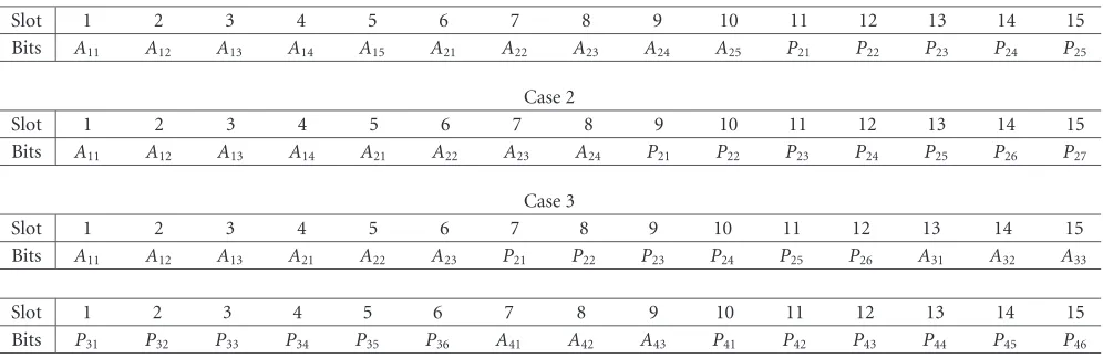
Table1: Frame structures for quantized feedback. Case 1: two transmit antennas and one receive antenna, (5, 5) quantization : 5 bits for the absolute value component and 5 bits for the phase component of each vector element;Aij:jth bit for the absolute value ofith vector element;
Pij:jth bit for the phase ofith vector element. Case 2: two transmit antennas and 1 receive antenna, (4,7) quantization. Case 3: four transmit
antennas and 1 receive antenna, (3,6) quantization.
Case 1
Slot 1 2 3 4 5 6 7 8 9 10 11 12 13 14 15
Bits A11 A12 A13 A14 A15 A21 A22 A23 A24 A25 P21 P22 P23 P24 P25
Case 2
Slot 1 2 3 4 5 6 7 8 9 10 11 12 13 14 15
Bits A11 A12 A13 A14 A21 A22 A23 A24 P21 P22 P23 P24 P25 P26 P27
Case 3
Slot 1 2 3 4 5 6 7 8 9 10 11 12 13 14 15
Bits A11 A12 A13 A21 A22 A23 P21 P22 P23 P24 P25 P26 A31 A32 A33
Slot 1 2 3 4 5 6 7 8 9 10 11 12 13 14 15
Bits P31 P32 P33 P34 P35 P36 A41 A42 A43 P41 P42 P43 P44 P45 P46
quantization. It is seen that the system achieves a good per-formance for the speeds lower than 30 km/h, and the BER curves are shown as “floors” whenvis higher than 30 km/h. The appearance of such “floor” is due to the severe mismatch between the precoding and the downlink channel. Similarly, Figure 6agives the BER performances of the system employ-ing the beamformemploy-ing with four transmit antennas, where the average eigenvectors over two frames are losslessly fed back. It is seen that the BER performances degrade to “floors” for the speeds higher than 15 km/h. It is observed from (6) that the frame-based feedback approach is feasible for the beam-forming system under the low-speed cases. In particular, it is feasible for the system employing two transmit antennas and four transmit antennas, under the cases ofv≤25 km/h and v≤10 km/h, respectively.
3.2.3. Quantization of the feedback
Table 1shows the feedback frame structures for the MIMO system employing beamforming schemes, that is, the quan-tization of the elements of the eigenvector to be fed back. We consider three cases here. Case 1 and Case 2 are con-trived for the beamforming system with two transmit an-tennas. These two bit allocation strategies of one feedback frame are, namely, (5, 5) and (4, 7) quantized feedback, re-spectively. In particular, (5, 5) quantized feedback allocates 5 bits each to the absolute value and the phase component of one eigenvector element; and (4, 7) quantized feedback al-locates 4 bits and 7 bits to the absolute value and the phase component of one eigenvector element, respectively. Case 3, namely, (3, 6) quantized feedback, is contrived for the beam-forming system with four transmit antennas. Two feedback frames are allocated for the average eigenvector over two frames. Note that relatively more bits should be allocated to the phase component, since the error caused by quantiza-tion is more sensitive to the preciseness of the phase com-ponents than that of the absolute value comcom-ponents
more-over, our simulations show that the (5, 5) and (4, 7) quan-tized feedback approaches actually have very approximated performances.
4. SIMULATION RESULTS FOR WCDMA SYSTEMS
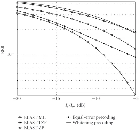
In the simulations, we adopt one receive antenna (nR =1), which is a realistic scenario for the WCDMA downlink re-ceiver. For the multipath fading channel in the WCDMA sys-tem, the number of multipath is assumed to be four (L = 4), and the mobile speed is assumed to be three kilome-ters per hour (v = 3 km/h). QPSK is used as the modula-tion format. The performance metric is BER versus signal-to-interference-ratio (Ic/Ior).Ic/Ioris the power ratio between the signal of the desired user and the interference from all other simultaneous users in the WCDMA system. Subse-quently, several cases with different transmission rates over two and four transmit antennas are studied.
BLAST versus linear precoding
−5
−10
−15
−20
Ic/Ior(dB) 10−1
BER
BLAST ML BLAST LZF BLAST ZF
Equal-error precoding Whitening precoding
Figure 7: BER comparisons between the BLAST and the trans-mit precoding schemes:nT = 4 and nR = 1; four QPSK
sym-bols/transmission;v=3 km/h,L=4.
STBC versus beamforming
Figure 8 gives the performance comparisons between the Alamouti STBC and the beamforming schemes for a rate of one symbol per transmission over two transmit antennas (nT =2). The effects of the quantized feedback approach is
also shown in Figure 8. In particular, the cycled line is the BER performance when perfect channel knowledge is avail-able at both the transmitter and the receiver. The solid line is the performance when perfect channel knowledge is avail-able at the receiver and the frame-based feedback without quantization in Section 3.2.2 is adopted. It is seen that the frame-based feedback approach only causes very trivial per-formance degradation. The asteriated line is the perper-formance when perfect channel knowledge is available at the receiver and the frame-based feedback with (4, 7) quantized feedback approach inSection 3.2.3is adopted. It is seen that the quan-tization of the feedback only generates about 0.5 dB perfor-mance loss. Moreover, the triangled line is the perforperfor-mance when the channel estimator in Section 3.1.2, the subspace tracking in Section 3.2.1, and the (4, 7) quantized feedback approach are adopted. It is shown that the subspace track-ing and the channel estimation cause about 1 to 1.5 dB per-formance degradation. Finally, the squared line is the perfor-mance of the Alamouti STBC, where the channel estimator is adopted at the receiver. It is observed fromFigure 8that the WCDMA system employing beamforming can have a bet-ter performance than that employing the Alamouti STBC scheme, though the performance gain is not very evident.
Figure 9gives the comparison between the beamform-ing scheme and the rate-one STBC strategy discussed in Section 2.2.2for a rate of one symbol per transmission over four transmit antennas (nT =4). Similarly, perfectly known channel knowledge, estimated channel knowledge, lossless
−10
−11
−12
−13
−14
−15
−16
−17
−18
−19
−20
Ic/Ior(dB) 10−3
10−2 10−1
BER
BF, perfectly known channel
BF, perfectly known channel, lossless feedback BF, perfectly known channel, quantized feedback BF, subspace tracking, quantized feedback Alamouti STBC, estimated channel
Figure8: BER comparisons between Alamouti and beamforming with subspace tracking and quantized feedback schemes:nT = 2
and nR = 1; one QPSK symbol/transmission;v = 3 km/h; (4, 7)
quantized feedback.
−10
−11
−12
−13
−14
−15
−16
−17
−18
−19
−20
Ic/Ior(dB) 10−4
10−3 10−2 10−1 100
BER
BF, known channel
BF, known channel, lossless feedback BF, known channel, quantized feedback BF, PASTd, quantized feedback Rate-1 STBC, (ML)
Rate-1 STBC, (LZF)
Figure 9: BER comparisons between rate-one STBC and beam-forming with subspace tracking and quantized feedback schemes:
nT =4 andnR =1; one QPSK symbol/transmission;v=3 km/h;
(3, 6) quantized feedback.
Table2: Summary of the performance comparisons of the MIMO techniques.
(a)
High-rate transmission MIMO techniques Channel information BER performance
Four symbols/transmission overnT=4 BLAST Receiver Better
Transmit precoding Transmitter/receiver Worse
(b)
Diversity transmission MIMO techniques channel Information BER performance
One symbol/transmission overnT =2 Beamforming Transmitter/receiver Better
Alamouti Receiver Worse
One symbol/transmission overnT=4
Beamforming Transmitter/receiver Better
Rate-one STBC Receiver Worse
Two symbols/transmission overnT=4
Transmit precoding Transmitter/receiver Worse
Rate-two STBC Receiver Better
the transmitter and the receiver; the second curve is the re-sult of the beamforming scheme with perfectly known chan-nel knowledge at the receiver and the frame-based feedback without quantization; the third curve is the result of the beamforming scheme with perfectly known channel knowl-edge at the receiver and the frame-based feedback with (3, 6) quantization; the fourth curve is the result of channel esti-mator, subspace tracker, and the frame-based feedback with (3, 6) quantization; the top two curves are the results of the rate-one STBC scheme with different detection methods. It is observed fromFigure 9that the beamforming can achieve a much better performance than the STBC for the case of four transmit antennas.
Moreover, it is also well confirmed that the subspace tracking algorithm discussed in Section 3.2.1, the frame-based feedback in Section 3.2.2, as well as the quantization approach discussed inSection 3.2.3offer a practical way of realizing beamforming in MIMO WCDMA systems.
5. CONCLUSIONS
In this paper, we have analyzed and compared the perfor-mance of three MIMO techniques, namely, BLAST, STBC and linear precoding/decoding, and considered their appli-cations in WCDMA downlink systems. For a certain trans-mission rate, we compared the different scenarios with dif-ferent transmit antennas both analytically in terms of the av-erage receiver SNR, as well as through simulations in terms of the BER performance. To cope with the channel feedback in WCDMA systems for beamforming, we adopted a sub-space tracking method with a quantized feedback approach to make the principle eigenspace of the MIMO channel avail-able to the transmitter.
Some instructive conclusions are drawn in this study. On the one hand, the optimal BLAST scheme can achieve the best performance in the high-rate transmission scenario, al-though with channel knowledge available at the transmit-ters, no performance gain is achievable by the linear
precod-ing/decoding schemes without employing adaptive modula-tion. On the other hand, the beamforming scheme achieves better performances than the STBC schemes in the diversity transmission scenario.Table 2 gives a summary of the per-formance comparisons of the MIMO techniques in different scenarios. Moreover, it is well confirmed the effectiveness and feasibility of the combination of the subspace tracking algo-rithm and the quantized feedback approach for beamform-ing transmission in the MIMO WCDMA system. Finally, we note that in this paper, we only consider thelinearprecoding scheme. Significant performance improvement is expected when nonlinear precoder (e.g., adaptive modulation and bit loading) is employed [26,27,28].
ACKNOWLEDGMENT
This work was supported in part by the U.S. National Science Foundation (NSF) under Grants 0225721 and CCR-0225826.
REFERENCES
[1] C.-N. Chuah, D. N. C. Tse, J. M. Kahn, and R. A. Valenzuela, “Capacity scaling in MIMO wireless systems under correlated fading,”IEEE Transactions on Information Theory, vol. 48, no. 3, pp. 637–650, 2002.
[2] G. J. Foschini and M. J. Gans, “On limits of wireless com-munication in a fading environment when using multiple an-tennas,” Wireless Personal Communications, vol. 6, no. 3, pp. 311–355, 1998.
[3] D.-S. Shiu, G. J. Foschini, M. J. Gans, and J. M. Kahn, “Fad-ing correlation and its effect on the capacity of multielement antenna systems,”IEEE Trans. Communications, vol. 48, no. 3, pp. 502–513, 2000.
[4] O. Damen, A. Chkeif, and J.-C. Belfiore, “Lattice code decoder for space-time codes,” IEEE Communications Letters, vol. 4, no. 5, pp. 161–163, 2000.
[6] G. D. Golden, C. J. Foschini, R. A. Valenzuela, and P. W. Wolniansky, “Detection algorithm and initial laboratory re-sults using V-BLAST space-time communication architec-ture,”Electronics Letters, vol. 35, no. 1, pp. 14–16, 1999. [7] H. Sampath, P. Stoica, and A. Paulraj, “Generalized linear
precoder and decoder design for MIMO channels using the weighted MMSE criterion,” IEEE Transactions on Communi-cations, vol. 49, no. 12, pp. 2198–2206, 2001.
[8] S. M. Alamouti, “A simple transmit diversity technique for wireless communications,” IEEE Journal on Selected Areas in Communications, vol. 16, no. 8, pp. 1451–1458, 1998. [9] V. Tarokh, H. Jafarkhani, and A. R. Calderbank, “Space-time
block codes from orthogonal designs,” IEEE Transactions on Information Theory, vol. 45, no. 5, pp. 1456–1467, 1999. [10] V. Tarokh, H. Jafarkhani, and A. R. Calderbank, “Space-time
block coding for wireless communications: performance re-sults,”IEEE Journal on Selected Areas in Communications, vol. 17, no. 3, pp. 451–460, 1999.
[11] Z. Hong, K. Liu, R. W. Heath, and A. M. Sayeed Jr., “Spa-tial multiplexing in correlated fading via the virtual channel representation,” IEEE Journal on Selected Areas in Communi-cations, vol. 21, no. 5, pp. 856–866, 2003.
[12] L. Zheng and D. N. C. Tse, “Diversity and multiplexing: a fun-damental tradeoffin multiple-antenna channels,”IEEE Trans-actions on Information Theory, vol. 49, no. 5, pp. 1073–1096, 2003.
[13] K. Majonen and M. J. Heikkila, “Higher data rates with space-time block codes and puncturing in WCDMA systems,” in
Proc. IEEE International Symposium on Personal, Indoor, and Mobile Radio Communications (PIMRC ’01), pp. 36–40, San Diego, Calif, USA, October 2001.
[14] D. Samardzija, P. Wolniansky, and J. Ling, “Performance eval-uation of the VBLAST algorithm in W-CDMA systems,” in
IEEE Vehicular Technology Conference (VTC ’01), vol. 2, pp. 723–727, Atlantic City, NJ, USA, October 2001.
[15] Texas Instruments, “Space-time block coded transmit an-tenna diversity for WCDMA,” proposal TDOC# 662/98 to ETSI SMG2 UMTS standards, December 1998.
[16] Lucent Technologies, “Downlink diversity improvements through space-time spreading,” proposal 3GPP2-C30-19990817-014 to the CDMA-2000 standard, August 1999. [17] B. C. Banister and J. R. Zeidler, “Tracking performance of a
gradient sign algorithm for transmit antenna adaptation with feedback,” inProc. IEEE Int. Conf. Acoustics, Speech, Signal Processing (ICASSP ’01), Salt Lake City, Utah, USA, May 2001. [18] B. C. Banister and J. R. Zeidler, “Transmission subspace track-ing for MIMO communications systems,” inProc. IEEE Global Telecommunications Conference (GLOBECOM ’01), vol. 1, pp. 161–165, San Antonio, Tex, USA, November 2001.
[19] W. Utschick, “Tracking of signal subspace projectors,” IEEE Transactions on Signal Processing, vol. 50, no. 4, pp. 769–778, 2002.
[20] X. Wang and H. V. Poor, “Blind multiuser detection: a sub-space approach,” IEEE Transactions on Information Theory, vol. 44, no. 2, pp. 677–690, 1998.
[21] Third Generation Partnership Project, “Tx diversity solutions for multiple antennas (release 5),” proposal 3G TR25.869 V0.1.01 to Technical Specification Group Radio Access Net-work, November 2001.
[22] G. J. Foschini, G. D. Golden, R. A. Valenzuela, and P. W. Wolniansky, “Simplified processing for high spectral effi-ciency wireless communication employing multi-element ar-rays,”IEEE Journal on Selected Areas in Communications, vol. 17, no. 11, pp. 1841–1852, 1999.
[23] B. Hochwald, T. L. Marzetta, and C. B. Papadias, “A trans-mitter diversity scheme for wideband CDMA based on
space-time spreading,”IEEE Journal on Selected Areas in Communi-cations, vol. 19, no. 1, pp. 48–60, 2001.
[24] C. B. Papadias and G. J. Foschini, “A space-time coding approach for systems employing four transmit antennas,” inProc. IEEE Int. Conf. Acoustics, Speech, Signal Processing (ICASSP ’01), pp. 2481–2484, Salt Lake City, Utah, USA, May 2001.
[25] T. L. Marzetta, “Blast training: estimating channel char-acteristics for high capacity space-time wireless,” in Proc. 37th Annual Allerton Conference on Communication, Control, and Computing, pp. 958–966, Monticello, Ill, USA, September 1999.
[26] P. S. Chow, J. M. Cioffi, and J. A. C. Bingham, “A practical dis-crete multitone transceiver loading algorithm for data trans-mission over spectrally shaped channels,” IEEE Trans. Com-munications, vol. 43, no. 2, pp. 773–775, 1995.
[27] R. F. H. Fischer and J. B. Huber, “A new loading algorithm for discrete multitone transmission,” inProc. IEEE Global Telecommunications Conference (GLOBECOM ’96), pp. 724– 728, London, England, November 1996.
[28] B. S. Krongold, K. Ramchandran, and D. L. Jones, “Com-putationally efficient optimal power allocation algorithms for multicarrier communication systems,” IEEE Trans. Commu-nications, vol. 48, no. 1, pp. 23–27, 2000.
Chuxiang Lireceived the B.S. and M.S. de-grees from the Department of Electronics Engineering, Tsinghua University, Beijing, China, in 1999 and 2002, respectively. He is currently working toward the Ph.D. de-gree in the Department of Electrical En-gineering, Columbia University, New York, NY. His research interests fall in the area of wireless communications and statistical sig-nal processing.
Xiaodong Wang received the B.S. degree in electrical engineering and applied math-ematics (with the highest honor) from Shanghai Jiao Tong University, Shanghai, China, in 1992; the M.S. degree in electri-cal and computer engineering from Purdue University in 1995; and the Ph.D. degree in electrical engineering from Princeton Uni-versity in 1998. From July 1998 to Decem-ber 2001, he was an Assistant Professor in