
V/F Control for Induction Motor Drive Fed by
Photovoltaic Generator
N.Aouani1, R.Dhifaoui2
Assistant Professor, Research Unit LACCS, National School of Engineering of Tunis, Tunisia1
Professor, Research Unit ERCO, National Institute of Applied Sciences and Technology, Tunisia2
ABSTRACT: This Article studies the V/f control configuration of a Photovoltaic pumping system. The solar generator
delivers a direct continuous voltage, that is been inverted into an alternative one by mean of a PWM implemented strategy on the converter. The V/f strategy is studied into two phases, an open loop control and a closed loop one. The paper highlights the technique of keeping constant the V/f ratio, while the machine’s speed is in variation. Thus, insuring to keep constant the maximum torque and the flux of the induction motor.
KEYWORDS: PV Generator, DC/AC converter, induction motor, PWM approach, V/f control.
I.INTRODUCTION
Because of many environmental and economic reasons, there is an increasing interest in the deployment of renewable energy sources. In addition, the power system needs to be expanded [1].
One of the most promising renewable energy sources is the photovoltaic (PV) energy source. The increasing interest in PV-based sources is attributable to their many advantages such as ease of installation, less maintenance, and long lifetime [2].
Also, solar energy is not only an answer to today’s energy crisis but is an environmental friendly form of energy. Photovoltaic (PV) generation is an efficient approach for using the solar energy. Solar panels (an array of photovoltaic cells) are now extensively used for running street lights, for powering water heaters and to meet domestic loads. The cost of solar panels has been constantly decreasing which encourages its usage in various sectors. One of the applications of this technology is used in irrigation systems for farming. This is green way for energy production which provides free energy once an initial investment is made [3].
Solar power depends upon the availability and intensity of solar radiation reaching the solar panels and provides power output that is converted to AC power by appropriately rated DC/AC inverters [4].
What we dispose in this article is a Simuation of the whole photovoltaic pumping system. All the parts are represented on Matlab Simulink and the results are recovered at the end.
As for the control approach applied, we have chosen to implement the V/f control method. In fact, there are various methods for the speed control of an Induction Motor [5]. They are: Pole Changing, Variable Supply Frequency Control, Variable Supply Voltage Control , Variable Rotor Resistance Control , V/f Control , Slip Recovery, Vector Control . Of the above mentioned methods, V/f Control is the most popular and has found widespread use in industrial and domestic applications because of its ease-of-implementation.
The main purpose of this work is to develop a model to implement V/f control of an induction motor. The whole system being fed by solar panels. Before that, the step of programming a PWM Inverter that drives the induction motor is necessary. In this sense, PWM signal generation, and Inverter topologies are also presented and simulated.
In this article, we present the design and simulation of a Photovoltaic system, implementing a V/f control technique (scalar control). The approach is adopted permitting an operating with maximum power provided by the PV Generator in any weather conditions. The PV system elements are: the PV generator, the three-phase PWM (Pulse Width Modulation) voltage inverter, and the induction motor coupled to a centrifugal pump. The induction motor based PV pumping systems offers an Alternative for a more reliable free system [6].
torque and the flux while keeping constant the ratio V/f. Also, we highlight the improvement brought by closed loop control compared to open loop one, this, in fastening the system’s response and the stability state reaching.
II.SYSTEM MODEL AND ASSUMPTIONS
The studied system is composed of three principle blocks: the photovoltaic generator, the DC/AC converter, and the induction machine. For each block, we enhance the general modeling and the different characteristics we dispose in our system. The global model is given in Fig.1.
Fig .1 Configuration of the Photovoltaic System.
II.1. PHOTOVOLTAIC GENERATOR MODEL
A Photovoltaic Generator is composed as given in Fig. 2:
N
bp branches in Parallel. Each branch includesN
mspanels in serial. In each panel, there areN
cscells in serial [7].p
i
is the current delivered by one cell andv
pthe voltage at its terminal.Fig. 2: Assembly of Solar pannels.
In order to compare the generation of a single cell towards a whole photovoltaic generator, we can write:
p p bp
Then, the photovoltaic Current Ip in the Photovoltaic Generator is given by:
1
[ (exp( p ) 1)]
p bp ph s
T cs ms
V
I N I I
V N N
= - - (2)
Where:
ph
I
: is the given current under a given illumination.s
I
: is the current of opposite saturation of the diode.p
V
: is the output voltage of a photovoltaic generator.bp
N
: is the number of parallel branches in the Photovoltaic Generator.cs
N
: is the number of cells in serial.ms
N
: is the number of panels in serial.T
V
: is the thermal potential, it is given by:B T
j
nK T V
q
= (3)
q: is the charge of an electron
(
1, 6.10- 13C)
.
B
K : is the constant of BOLTZMAN (J/°K).
j
T : is the Temperature of Diode Junction (°K).
n : is the Ideality factor of the solar cell; factor between 1 and 5 in the practice.
The optimal operating point of the PV generator is characterized by an optimal power value that is calculated such that:
_ _ _
p opt p opt p opt
P = I ´ V (4)
Where
_
p opt
V is the optimal output voltage of the generator:
_ 0.76
p opt co
V = V (5)
co
V is the open circuit voltage.
_
p opt
I is the optimal current,
_ 0.9
p opt cc
I = I (6)
cc
I is the short circuit current.
II.2. THREE PHASE PWM INVERTER
An inverter is a circuit that converts DC (Direct current) sources to AC (Alternating current) sources. Inverters are used in a wide range of applications from small switched power supplies for a computer to large electric utility applications to transport bulk power [8].
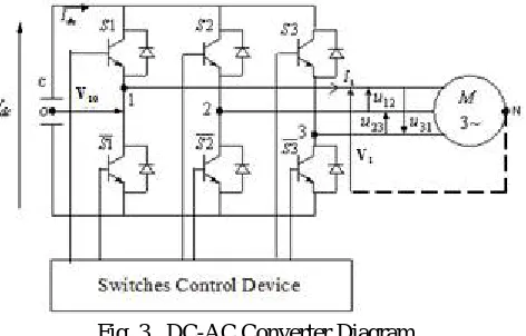
Fig .3 DC-AC Converter Diagram.
As shown in Fig.3, the inverter is powered by a DC voltage source Vdc. It is composed of three arms, each arm represents a single-phase bridge circuit.
Every bridge contains two switches, each one realized through a transistor (or a thyristor) in antiparallel with a diode called the return current or feedback diode. The switches of a same arm of the DC-AC converter are complementary in order to avoid causing short-circuit in the power source. This is also the case for the logic signals associated to the control. If we design by Si the control associated to the switch i, we could write the following relation:
1 1 1
S S ; 2S 1 S2; 3S 1 S3 (7) In a general way; we note:
- V V1, 2,V3: The simple voltages of the machine.
- U12,U23,U31 : The composed voltages of the machine.
We introduce then a fictive point O ; center of the continuous source , in order to establish the necessary equations.
According to the structure given by the figure Fig.3, the voltage on V10equals 2
dc
V
when 1S =1 and S1= 0 ; it
becomes
)
( 2 - Vdc
when
S
1
=
0
and S1= 1. The same analysis is valid forV
20if we use the controlsS
2
and S2,and for V30, if we use
S
3
and S3 . The voltages V10,V20,V30, are given by the following relations : 1020
30
( 1 1 ) (2 1 1)
2 2
( 2 2) (2 2 1)
2 2
( 3 3) (2 3 1)
2 2
dc dc
dc dc
dc dc
V V
V S S S
V V
V S S S
V V
V S S S
ìï
ï = - =
-ïï ïï
ïï = - =
-í ïï ïï
ï = - =
-ïï ïî
(8)
The composed voltages are given by:
12 10 20
23 20 30
31 30 10
( 1 2)
( 2 3)
( 3 1)
dc
dc
dc
U U U
V V S S V
V V S S V
V V S S V
= - =
-= - =
-= - =
-ìï
ïïï
í
ïï
ïïî
(9)
12 31 1
12 31
2 1 12
12 31
3 1 31
3 2 3 2 3 U V V U V U U U V U U V U -= - -= - = + = + =
ìï
ïï
ïï
ïïï
í
ïï
ïï
ïï
ïïî
(10)If we replace U12,U23,U31 , in (9) by (10), we get:
1
2
3
(2 1 2 3) 3
(2 2 1 3) 3
(2 3 1 2) 3 dc dc dc V V V V
S S S
V
S S S
V
S S S
= - -= - -= -
-ìï
ïï
ïï
ïïï
í
ïï
ïï
ïï
ïïî
(11)The system (11) can be written as a matrix notation by:
1 2 3
2 1 1 1
1 2 1 2
3
1 1 2 3
dc V V V S V S S - -= - --
-é ù
é
ùé ù
ê ú
ê
úê ú
ê ú
ê
úê ú
ê ú
ê
úê ú
ê ú
ê
úê ú
ë û
ë
ûë û
(12)We note that the current
I
dc provided by the supplyV
dc (Fig. 3) to the DC/AC converter is expressed considering thecurrents I1,I2,I3 , by:
1 1 2 2 3 3
dc
I = S I +S I +S I (13)
The power delivered by the continuous source is such that:
dc dc
P=V I (14)
The expression (14) shows how the converter transmits fully to the load, the power delivered by the continuous source.
II.3. MODELING OF THE INDUCTION MOTOR
Induction Motors are often termed the “Workhorse of the Industry”. This is because it is one of the most widely used motors in the world. It is used in transportation and industries, and also in household appliances, and laboratories [5]. The major reasons behind the popularity of the Induction Motors are: They are cheap compared to DC and Synchronous Motors , Induction Motors are very rugged in construction. Their robustness enables them to be used in all kinds of environments and for long durations of time. Induction Motors have high efficiency of energy conversion. Also they are very reliable [5].
We give below the induction machine’s equation, in order to integrate them after, in the photovoltaic system’s Simulink model.
A. Electric Equations
The electric equations of the Induction Machine are given by:
j w j
= +
-ds s ds ds s qs
d
V R I
dt (15)
qs s qs qs s ds
d
V R I
dtj w j
j w w j
= + - ( - )
dr r dr dr s r qr
d
V R I
dt (17)
j w w j
= + + ( - )
qr r qr qr s r dr
d
V R I
dt (18)
jds = L Is ds +M Isr dr (19)
jqs = L Is qs + M Isr qr (20)
jdr = L Ir dr + M Isr ds (21)
jqr = L Ir qr + M Isr qs (22)
dr
V ,Vqr are the Direct and Inverse components of the rotor voltage.
ds
V ,Vqsare the Direct and Inverse component of the stator voltage.
dr
,qr are Direct and Inverse components of the rotor flux.
ds
, qs are Direct and Inverse component of the stator flux.
dr
I ,Iqrare Direct and Inverse components of the rotor current.
ds
I ,Iqsare Direct and Inverse components of the stator
s
R,Rr are Stator and Rotor resistances.
s
L ,Lr are Stator and Rotor inductances.
r
is the Electric speed of the rotor (rotational speed).
s
is the Synchronism speed (Stator pulsation).
B.Mechanical equations
Fundamental dynamic relationship applied to the rotating part of the induction machine, adopting the motor convention is given by:
r
r em r
d
J f C C dt
W
+ W = - (23)
Where
C
em andC
r design respectively the electromagnetic and the resistant torques.r
W
is the mechanical speed. We hence have the relation:w
r=
p
W
r (24)Where
p
is the number of pair poles.We get then the following equation representing the induction motor:
( )
w
w
+ =
-r
r em r
d
J f p C C dt
(25)
III. CONTROL STRATEGY
The choice adopted for the strategy control of the PV system, was made based on V/f approach. This technique is based
on maintaining constant the
V
III.1. THE PWM CONTROL
PWM voltage source static frequency inverters presently comprehend the most used equipments to feed low voltage industrial motors in applications that involve speed variation. They work as an interface between the energy source (DC power line) and the induction motor [9].
The simplest way to generate a PWM signal is the intersective method, which requires only a sawtooth or a triangle waveform (easily generated using a simple oscillator) and a comparator.
PWM is often used to control the supply of electrical power to another device such as in speed control of electric motors.
Let’s consider ft and fs the frequencies of respectively the triangle waveform and the sinusoidal one. If ft is choosen big comapred to fs, then the harmonic frequencies are rejected so far and then can be eliminated by filtering.
In the simulation and results part, we present the PWM Generator where the pulses are generated by comparing a triangular carrier waveform to a reference signal. The parameters are also given.
III.2. THE V/f CONTROL STRATEGY
The scalar control is based on the original concept of a frequency inverter: a signal of certain voltage/frequency ratio is imposed onto the motor terminals and this ratio is kept constant throughout a frequency range, in order to keep the magnetizing flux of the motor practically unchanged [9].
Conjointly, there are various advantages for V/f Control, such as [5]: It provides good range of speed.
It gives good running and transient performance. It has low starting current requirement.
It has a wider stable operating region.
Voltage and frequencies reach rated values at base speed.
The acceleration can be controlled by controlling the rate of change of supply frequency. It is cheap and easy to implement
Elements of the control
The V/f control scheme, for asynchronous machine, is given by the following equation [10]:
2 1
1 ( )
s s s
s s
V w
t w
= F + (26)
s
V is the effective voltage of the sine wave,
s
w is the stator pulsation,
s
s s
L R
t = is the stator constant time,
s
f is the stator flux.
If we consider negligible the voltage fall due to the resistanceRs, we have:
s s s
V = f w (27)
What characterizes a law:
, K constant
s K s
V f =
(28)
A. Open Loop V/f Control
In this part, we aim to apply a V
f control strategy by maintaining constant the fraction
s s
V
f (28).
In this method, the stator voltage is kept constant, and the supply frequency is also static (50 Hz), what keeps the V/f ratio constant.
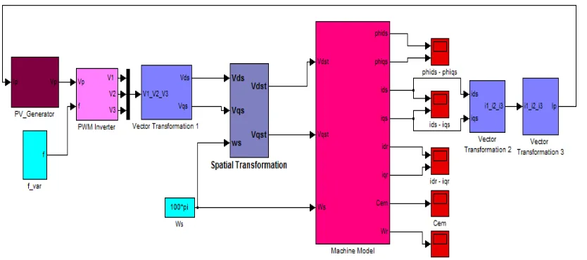
Fig.4 Simulink model of the V/f Open Loop Control, applied to the photovoltaic pumping system.
The Figure Fig. 4 shows the MATLAB code of the different parts of the PV system (PV Generator - PWM inverter- Induction Machine). The simulation and results of this part are shown next in the part IV.
B.Closed Loop V/f Control
As for the closed loop system, the diagram is given by Fig.5.
Fig. 5: Diagram of the closed loop V/f Control applied to the photovoltaic pumping system.
The closed loop V/f control applied to the PV system differs from the open loop V/f one. The frequency fsinjected to
the PWM inverter, is at this time, deduced from the stator pulsation
w
srelative to the induction machine.w
sis in factgenerated by a calculator, such that the slip pulsation is equal to 314.15 /
10 10
s rad s
w
IV. RESULTS AND DISCUSSION
The proposed methods are designed and tested on MATLAB / Simulink software.
In this part, we intend to implement the control approach to the whole system (Photovoltaic Generator – PWM inverter-Induction generator) given in Fig.1. The overall control procedure consists of two stages: one, in generating the adequate signals from the DC/AC converter, that is the PWM technique. In the second stage; we aim to implement the V/f technique, both in open and closed loop schemes. A comparison between the two schemes will be made.
The main result is that, by varying the magnitudes of V and f while keeping the V/f ratio constant, the flux and hence the torque can be kept constant throughout the speed range. Another result, is, the closed loop control makes faster the system’s response.
The related specific parameters of the PV array are carried out in the Table Tab.1.
Parameter Value
Number of parallel branches In the Photovoltaic Generator
N
bp 1Number of modules in serial
N
ms 15Number of cells in serial
N
cs 36Short circuit current Iccfor one cell 3.85A
Open circuit voltage Vco for one cell 21V
Standard condition of Temperature T 300°K
Standard condition of Illumination E 1000W m/ 2
Tab.1 Main Data for Phtovoltaic Generator.
The optimal operating point characteristics of the available generator, according to equations (4), (5) and (6), are
given by:Vp opt_ = 239.4V; , Ip_opt = 3.46A ; Pp opt_ = 830watt.
The related specific parameters of the induction machine are carried out in the Table Tab.2.
Electrical Parameter Value
Stator Resistance
R
s 23.7WRotor Resistance
R
r 16.1WStator Cyclical Inductance Ls 1.5808H
Rotor Cyclical Inductance Lr 1.5808H
Magnetizing Cyclical Inductance Msr =1.46H 1.46H Nominal Power
n
P 0.37Kw
Moment of Inertia J 3 2
35.e- Kg m.
Number of pair of poles p 1
Nominal Voltage
V
s (Delta) 220VNominal Voltage
V
s (Star) 380VLoad torque Cr Kr2 K 7.5248e6
The algorithm integration is the Runge-Kutta (ODE4) one, fixed step equal to 0.0001 s.
IV.1. PWM CONTROL
In order to feed the PWM inverter, the voltage Vdc mentioned in Fig.3, should satisfy the following condition [10] ;
s
2V
dc
V (29)
Where
V
s is the effective Simple voltage of the induction motor.dc
V
is itself the output voltage V p of the photovoltaic generator (Fig.2). It is equal to: Vp 15 21 315V.
For an input DC voltage of 315V, the circuit produces Three-phase AC voltage output. The load is delta-connected 220
s
V V
, and then it satisfies (29).
We are interested in simulating the behavior of the PWM inverter. The purpose is to generate three voltages V V1; 2;V3
(as given in equation (12)), that the fundamentals are with phase shift2
3
p
.
The considered DC-AC converter have the following characteristics for its supply: ft =1050Hz, fs=50Hz ,
1
a = and 315V
dc
V = .
The modulation depth ratio a is given by:
Vsn Vt
a = (30)
sn
V is the effective voltage of the sinusoidal waveform.
t
V is the effective voltage of the triangle waveform.
We illustrate in Fig.6 one of the output voltages of the three phases inverter, V1.
Fig. 6: Simple Voltage (in one phase) at the output of DC-AC converter for a PWM control strategy with 1050
t
f = Hz, 50
s
f = Hz a = 1 and Vdc = 315V .
IV.2. V/f CONTROL
In this part, the outputs of the three-phase inverter (Fig.6 is for one phase ) are connected to the induction machine. We do simulate the V/f control for both open and closed loop schemes.
The PV generator is the one that parameters are given in Tab.1, the induction machine’s data is given in Tab.2.
0.3 0.35 0.4 0.45
-250 -200 -150 -100 -50 0 50 100 150 200 250
Time[s]
S
im
p
le
V
o
lt
a
g
e
V
1
[
V
A. Open Loop V/f Control
We intend to maintain constant the ratio s s
V
f . The adopted diagram is the one given in Fig. 4.
= 220
s
V V and fs = 50Hz, thus s = 4.5
s
V
f .
The sinusoidal waveform generated to the PWM converter is based on a frequency signal , as given in Fig.7. It is hence a ramp where fs = 50Hz stabilizes at = 0.1t s.
Fig. 7. Frequency Ramp fs, generated to PWM inverter.
The following figures show us the behavior of the induction motor variables while applying the V/f open loop control.
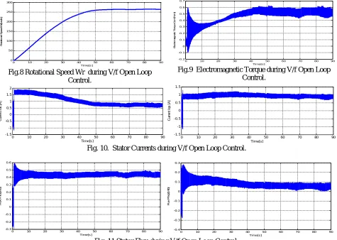
Fig.8 Rotational Speed Wr during V/f Open Loop Control.
Fig.9 Electromagnetic Torque during V/f Open Loop Control.
Fig. 10. Stator Currents during V/f Open Loop Control.
Fig. 11 Stator Flux during V/f Open Loop Control.
0 10 20 30 40 50 60 70 80 90 0 10 20 30 40 50 60 Time[s] F re q u e n c y R a m p f s ( H z )
0 10 20 30 40 50 60 70 80 90 0 50 100 150 200 250 300 Time[s] R o ta ti o n a l S p e e d W r[ ra d /s ]
0 10 20 30 40 50 60 70 80 90
-0.2 -0.1 0 0.1 0.2 0.3 0.4 0.5 0.6 0.7 Time[s] E le c tr o m a g n e ti c T o rq u e C e m [ N .m ]
0 10 20 30 40 50 60 70 80 90 -1.5 -1 -0.5 0 0.5 1 1.5 2 Time[s] C u rr e n t Id s [ A ]
0 10 20 30 40 50 60 70 80 90 -1.5 -1 -0.5 0 0.5 1 1.5 Time[s] C u rr e n t Iq s [ A ]
0 10 20 30 40 50 60 70 80 90 -0.3 -0.2 -0.1 0 0.1 0.2 0.3 0.4 0.5 0.6 Time[s] F lu x P h id s [W b ]
Figures Fig.8-11, show the responses of the Photovoltaic system, while a V/f open loop control, they especially highlight the behavior of the induction machine. It is clear that the rotational speed (Fig.8) attends the stability without any oscillation, it depends on the frequency fs = 50Hz and this one is maintained constant from t = 0.1s. The electromagnetic torque given in Fig. 9, also reaches the stability , altough there are some fluctuations due to the relatively high value stator resistance. As to currents and flux (Fig 10 and 11) , they also attend the steady state as the rotational speed of the motor evolves to reach the final value of 260rad s/ at steady state.
B.Closed Loop V/f control
The structure of the closed loop control of the Photovoltaic system is given in Fig. 5. The different variables of the system’s response are depicted in Figures Fig.12-15.
Fig. 12. Rotational speed during V/f Closed Loop Control.
Fig. 13. Electromagnetic torque during V/f Closed Loop Control.
Fig.14 : Stator Currents during the closed loop V/f Control.
Fig.15 : Stator Flux during the closed loop V/f Control.
One first conclusion we can reach from the curves allures, is that some variables are made to respond faster by the V/f closed loop control. We take for example, the rotational speed of the induction machine. It is shown on Fig.12 that it reaches the value of wr = 200rad s/ at = 20t s, while it takes more time to reach the same value in open loop V/f control ( = 30t sin Fig.8).
We observe the same behavior for the electromagnetic torque Cem. The value of Cem = 0.5 .N m is reached at
= 40
t s for Open loop control (Fig.9), whereas in closed loop control, Cem = 0.5 .N mat = 10t s.
Another important remark is, at t = 30s, the torque (Fig.13) becomes constant (Cem = 0.59 .N m) for a changing value of Rotor speed. This, as shown in Fig.5, whenever frequency is varied, the terminal voltage is also varied in order to maintain the V/f ratio constant. Hence Speed control is achieved in the Induction motor.
0 10 20 30 40 50 60 70 80 90
0 50 100 150 200 250 300 Time[s ] R o ta ti o n a l S p e e d W r[ ra d /s ]
0 10 20 30 40 50 60 70 80 90
0 0.1 0.2 0.3 0.4 0.5 0.6 0.7 Time[s] E le c tr o m a g n e ti c T o rq u e ( N .m )
0 10 20 30 40 50 60 70 80 90
0 0.1 0.2 0.3 0.4 0.5 Time [s] C u rr e n t Id s [ A ]
0 10 20 30 40 50 60 70 80 90
-0.7 -0.6 -0.5 -0.4 -0.3 -0.2 -0.1 0 Time [s] C u rr e n t Iq s [ A ]
0 10 20 30 40 50 60 70 80 90
0 0.05 0.1 0.15 0.2 0.25 0.3 0.35 Time[s] F lu x P h id s [p u ]
0 10 20 30 40 50 60 70 80 90
Finally, as can be observed on Fig.14 and Fig.15 , both the stator currents and flux, exhibit high transients during the starting of the motor. They then settle down to constant values in the steady state.
V.CONCLUSION
We have utilized in this paper a group of solar pannels feeding a pumping device. The DC supply voltage taken from it, is adapted in order to feed a three phase PWM inverter. The PWM signals are generated by comparing triangular waveform with a sinusoidal one.
Besides, a V/f control is implemented on the induction motor. Both open loop and closed loop strategies aimed to keep the V/f ratio constant. Especially in the closed loop scheme, the voltage source Inverter varied the magnitude of the terminal voltage in a way that V/f ratio remains the same. The adopted approach contributed in keeping the maximum torque whereas the rotor speed of the machine is in expansion. The electric variables of the motor present some fluctuations during the motor’s boot but tend to stabilize whenever the scalar control is applied.
REFERENCES
[1] A. Elrayahh, Y. Sozer, M. Elbuluk, “MicroGrid-Connected PV-Based sources”, IEEE Industry Applications Magazine, March/April 2015, pp19-29.
[2] F. A Farrest and M.G. Simoes, “Integration of Alternative Sources of Energy”, ISBN: 978-0-471-71232-9, 504 pages, Wiley-IEEE Press, February 2006.
[3] V. B. Shinde and S. S. Wandre “Solar photovoltaic water pumping system for irrigation: A review”, Vol. 10, N°22, pp. 2267-2273, 28 May2015. [4] Dev Paul and P. (Ben) R. Chavdarian, “Undercurrent protection power system: A novel ground-fault protection relay scheme”, IEEE Industry Applications Magazine, Vol. 21, N°1, Jan 1, 2015.
[5] Devraj Jee, Nikhar Patel, “V/f control of induction motor drive”, Department of Electrical Engineering National Institute of Technology Rourkela-769008 ODISHA, May 2013.
[6] S. R. Bhat, “Performance Optimisation of Induction Motor-Pump using Photovoltaic Energy Source”, IEEE Transactions on Industry Applications, Vol. IA- 23No. 6, pp 995–1000, 2008.
[7] H. Brahmi, N. Rebai, R. Dhifaoui, “Modeling and Simulation of Photovoltaic Generator”, International Science Index, Vol: 8 No: 9 Part VIII, November 2014.
[8]K. P. Kumar, K. Saikishore, “Analysis and simulation of solar powered water pump using three phase induction motor”, International Journal of Advanced Research in Electrical, Electronics and Instrumentation Engineering, Vol. 2, Issue 11, November 2013.
[9] Induction motors fed by PWM frequency inverters, Technical guide, 2007.
[10] N. Aouani, « Photovoltaic Pumping System: Studies, Simulation and a Control Strategy including an MPPT Approach”, End of Engineering Studies Project, National Institute of Applied Sciences and Technology of Tunis, January 2006.
BIOGRAPHY
Nedia Aouani is born in Tunisia. She received her engineering diploma in
industrial and automatic computing from the National Institute of Applied Sciences and Technology (INSAT), University of Tunis Carthage, in Tunis in 2006.
She also received her master’s diploma in the same field in July 2007. Nedia has published many papers in the field of robust control and renewable energy. She holds a PhD in ‘robust control’ from the Engineering School of Tunis, in collaboration with LAAS of Toulouse.
N. Aouani is with the unit of research LACCS, ENIT, Tunisia, Campus universitaire, BP 37, 1002, Le Bélvédère, 1002,Tunisia.
Rachid. Dhifaoui is born in Tunisia. He received “Doctorat d’Etat” in Electrical

![Fig. 13. Electromagnetic torque during V/f Closed Time[s]](https://thumb-us.123doks.com/thumbv2/123dok_us/7780696.1285038/12.595.67.536.298.639/fig-electromagnetic-torque-during-v-f-closed-time.webp)
