Impact of Power Oscillation Damping and Control of Voltage Dip by Using
FACTS Devices and Dual STATCOM Controller for DFIG
M Srikanth & D R CH Nookesh
Asst Prof Asst Prof
DIET DIET
Abstract
—
In a power system, faults are inevitable. In this paper, Doubly Fed Induction Generator (DFIG) and Synchronous Genera-tor (SG) are compared for fault performance and enhancement by using FACTS devices and dual STATCOM. If a symmetrical fault occurs in one of the line in dual path with fault resistance of 1 milli-ohm between phases and ground, the system behavior is studied. Surge currents will be formed and will flow in all lines, voltage de-creases, oscillations in real power flow occurs and thereby overall stability decreases. The fault current so produced is diverted to the capacitor by using dual-STATCOM controller to mitigate voltage sag and current swell. It is aimed to verify the behavior of SG and DFIG due to the fault and also to find better FACTS device to mitigate the voltage sag and surge currents and to damp power oscillations. Results proved that DFIG is more stubborn than SG and voltage is maintained by diverting surge currents, oscillations in real power flow from generator have damped and hence system stability and continuity of supply are enhanced. These disturbances are inherent and proposed STATCOM technique is having capability to maintain equilibrium during and post fault conditions. It is best suitable to maintain power system stability with uninterrupted power supply and to damp inter-area oscillations. The effectiveness of SG and DFIG based system was studied under four cases viz., case-1 without STATCOM, case-2 with single STATCOM, case-3 with SSSC, case-4 with UPFC and case-5 dual STATCOM.Index Terms
--
DFIG, Inter-area oscillations, Kundur two area testsystem, STATCOM, UPFC, Voltage Source Converter.
I. INTRODUCTION
It
is important to ensure proper steps in maintaining power sys-tem security while enhancing transfer capability and reliability. To achieve this advanced FACTS technology is promising; however it is very cost effective alternative. Among FACTS family SVC, STATCOM and UPFC are more suitable for improving power system stability when a severe disturbance occurs in a system [1-6]. These authors considered UPFC is a better device to damp oscillations due to disturbances due to external faults. In fact UPFC is having feature of series and shunt controller, it can con-trol both voltage and current and thereby reactive power of the system where it was connected. Static compensator (STATCOM) is capable of regulating voltage, control reactive power and also suitable for damping oscillations in the PSS incorporated syn-chronous generator during symmetrical fault conditions [7-9]. In series FACTS family, thyristor controlled series capacitor (TCSC) and static synchronous series compensator (SSSC) can dampin-ter-area oscillations [10] are suitable for hybrid applications. The disadvantage of these devices is removing from system because of any reason makes the work complicated and also continuity of supply disturbs.
DFIG is said to be in synchronism even if the voltage drop near grid decreases to zero and must regain its prefault state within specified time described by their country grid codes as scribed in [11]. The DFIG is operated with different FACTS de-vices [11-19] to improve grid restoring time and voltage mitiga-tion with HVDC –STATCOM for fault current limiting [12, 13], comparison of TCSC, UPFC, SVC and STATCOM for control-ling rotor speeds [14], series compensating device to damp oscil-lations using Eigen analysis [15], STATCOM with interface neu-ro-controller (INC) using dynamic programming [16], STATCOM to compensate rotor current and voltage compensation in real time environment [17], with symmetrical and asymmetrical grid faults compensation using DVR [18], damping control for offshore wind farm and marine current farm using STATCOM [19].
Aiming towards different objectives [22], maintaining stability, regulating voltage and mitigate harmonics, control of reactive power during and after transient operation, STATCOM or UPFC are chosen to be better alternatives. Optimal location of these devices also plays a major role in the performance of the system. The impedance of FACTS devices during fault time has to decrease so that fault current will be bypassed and when fault clears, this current has to be supplied to grid or respective load. So, these devices must be faster, bi-directional and has to operate dynamically during steady and transient situations [20, 21].
P a g e | 5421
to enhance dynamic response and robust system to overcome dis-turbances and parameter variations is given by [28]. Application of series compensator for power oscillation damping by varying inductive reactance of transmission line concept was proposed in [29] and based on Heffron- Philips model is given in [30].
A new real and reactive power coordinated theory was proposed for UPFC and role of SSSC and STATCOM was ex-plained clearly for performance enhancement is given in [31, 32]. For two area four machine system, stability indices were designed and explained for TCSC in [36]. In this paper root loci for inter-area mode for damping controllers were explained. Effect of pow-er system dynamics was explained in [37] and in [38] role of se-ries capacitors, phase shifters and controllable shunt capacitors for damping electromechanical oscillations was explained. Im-portance of FACTS devices like SVC, CSC and phase shifters for suppressing power system oscillations for SMIB is given in [39]. Selection of FACTS devices for small and large power systems for achieving better oscillations damping is given in [40]. In this paper, comparison was made between SVC, SSSC and UPFC for damping inter-area oscillations. For 2 areas 11 machine system with 2 SVC devices operating conditions without and with PSS using Eigen analysis and importance of FACTS devices was explained in [41]. For weak bus system, importance of UPFC and PSS was tested using PSO technique for system stability en-hancement is given in [42] and damping frequency oscillations in power system is given in [43]. Fundamentals on small signal and transient stability analysis for determining characteristics of system are shown in [44]. The three part series of [45] gives fun-damentals details for role of PSS, bus frequency, electric inputs and tuning of PSS. Fundamental idea in comparison of inter-area oscillations by using PSS, SVC and STATCOM using HOPF bi-furcation and extended Eigen analysis concept is studies for 50 machine 145 bus systems in [46].
In this paper, Kundur’s two area system is modified to have two synchronous generators (SG) in area-1 and two synchro-nous generators and a Doubly-Fed Induction Generator (DFIG) in area2. There are two parallel paths available in the midpoint of the system where two static compensators (STATCOMs) are connect-ed in each line to a common capacitor bank and the setup is callconnect-ed as dual-STATCOM. If replacing series controller with shunt con-troller for UPFC, it works as dual STATCOM. It has advantages as series pulse controller is not required and same pulses can be given to both the STATCOMs. The aim in the design of shunt controller is to act as low impedance path for short circuit current during fault condition, thereby surge currents can be diverted to VSC. If a symmetrical fault occurs in one of the line in dual path with fault resistance of 1 milli-ohm between phases and ground,
the system behaviour is studied.The paper first presents modified
Kundur’s test system by incorporating dual STATCOM in section 2, mathematical modelling of synchronous generator and STAT-COM are done in section 3. Section 4 describes control strategy for STATCOM, section 5 explains time domain simulation of system for five cases and section 6 gives conclusion followed by references.
II. CONFIGURATION OF THE TESTED SYSTEM
The one line diagram of equivalent power system used in this study is given in Fig.1. This system consists of four genera-tors of equal rating. The system is grouped under two areas; each synchronous generator is rated at 200MVA, 13.8KV and a step-up transformer with 210MVA, 13.8/230KV, and Δ-Үg is used for transmission. Busses 1 to 8 are treated as area1 and buses 8 to 3 are treated as area2. A three winding transformer of 60MVA, 230/230/20KV with lower voltage winding is used for STAT-COM connection.
The two STATCOMs share common DC link capacitor. The transmission line impedances Z1, Z2 and Z3 and generator and load parameters are taken from [23]. The details of overall system parameters are given in Appendix. For improving the ma-chine stability and for voltage regulation 5th order PSS and AVR are used. From the study of load flow analysis, the power flows from Area 1 to Area 2.
SG1
VDC
VSC
SG4 SG3 DFIG
IST1 IST2
VSC
AREA1 AREA2
SG2 1
3
20 2
120
110 12
4 14
10
11
Fig.1. Modified Kundur four machine two area system with DUAL-STATCOM
Each generator is equipped with prime-mover with gov-ernor system, automatic voltage regulator (AVR) and power sys-tem stabilizer (PSS). The AVR is modelled with gain for lag net-work and a limiter to control the excitation of field current of syn-chronous generator. The purpose of AVR is to regulate the stator output voltage to desired value or required as per grid voltage. The AVR is also used to control the power factor of synchronous generator. For improving the stability of the system by providing supplementary signals to AVR, PSS is used. The deviation in gen-eration value to reference value a supplementary signal is derived. The PSS is a lead-lag compensator better described by fifth order system.
A. Synchronous Generator
The synchronous block diagram is shown in Fig 2. The system consists of governor, voltage controller and system stabi-lizer. The difference between desired and actual speed is said to be speed error, it is controlled by speed governor. Based on the
difference in the speed (Δω), mechanical output (Pm) varies. The
deviation in terminal voltage (ΔVt) is derived from the difference
of Pm with ΔPm and Pe, where ΔPm is disturbances in mechanical
power and Pe is electric power output from generator. The transfer
function of G1 is Kp (1+
), which is used to control power
de-viations and also to produce voltage margin. The electric power output consists of power delivered to grid and copper and iron
losses. From two space analysis, output power can be derived. Pe
can also be derived from (Vreal*Ireal+Vimag*Iimag) and losses in
elec-tric power can be derived from + )*Ra, where real and
imag are real and imaginary parts of voltages and current and Ra is
armature resistance of SG. Xd, Xq, are direct (d) and
quad-rature (q) components of salient SG at steady state and at
sub-transient conditions. The difference in reference voltage (Vref),
generator terminal voltage and PSS voltage are controlled by
tun-ing the exciter gain and time constants (Ke, Teo) to get reference
voltage Ef. If Ef is added with Δid (Xq-Xq1) we get Ed reference
and armature quadrature component (Eq) can be obtained by
mul-tiplying Δid with (Xq- ). A first order transfer function is used to
control these parameters so as to get voltages . The
final output voltage from armature of synchronous voltage (Va)
can be obtained from√ . This voltage has to be
main-tained at desired values to maintain synchronism with grid and
other synchronous generators. The reference voltage (Vref or
ΔVref) is obtained from grid potential transformer and stabilizer
voltage (Vs or ΔVs) are obtained from PSS. The most widely used
lead-lag controller design for PSS is shown in Fig.3. Here ωo is
fundamental angular frequency which is equal to 2πf, where f is frequency of the generator.
Fig.2. Block Diagram representation of synchronous generator with voltage regulator and PSS
Fig.3. Block Diagram of 5th order PSS with speed regulator
B.Power system stabilizer (PSS)
The block diagram representation of 5th order PSS is shown in Fig.3. If a disturbance occur to power system, if the sys-tem regains its pre-disturbance state is defined as stable. During or after disturbance, oscillations in generator parameters take place and if these oscillations are damped quickly then system comes to
steady state operation. For oscillations damping PSS is used. Kpss
is PSS gain constant; Tw is washout time constant, its value is
about 30 seconds [15]. Lower than this value oscillations persist.
T1 and T3 are lead time constants and T2 and T4 are lag time
stants of the signal generator. For compensating excitation trol system and also to maintain local phase lag, lead time con-stants are to be tuned and to improve stability lag time concon-stants are used. From stability studies like Eigen or Root Locus, it is
observed that T2 and T4 values must be made smaller than T1 and
T3.
For active power oscillations damping,
= ) (1)
The above equation is very commonly used to explain the state of system for synchronous generator. For machine to
reach equilibrium
should be equal to zero. It is achieved when
and , where is measured from AC
lines using phase locked loop (PLL).
C. STATCOM and UPFC
Among FACTS family STATCOM plays a major role in damping power system oscillations [17, 18]. It is a shunt device used to control voltage by controlling reactive power in the sys-tem or injects current to regulate voltage dip at the point it is cou-pled. The stabilizing capability of STATCOM is higher than SVC and it can quickly control reactive power or power factor and can effectively damp power oscillations. In the literature dynamic performance of STATCOM with PID or other controllers are ana-lyzed using Eigen analysis. If the DC voltage across capacitor of STATCOM is maintained nearly constant then voltage oscillations can be easily controlled. The difference in magnitude of terminal voltages is related directly to reactive power flow in a network. Hence deviation in reactive power flow is compensated by STATCOM and hence voltage at coupling point can be main-tained constant by this device. Hence voltage at capacitor link has to be maintained constant. The series compensated devices like static synchronous series compensator (SSSC) may pose serious issues like sub-synchronous resonance, maintenance problems etc. The modeling and design of STATCOM is explained in detail in next section.
P a g e | 5423
or shunt FACTS family; hence much research is expected in this point of view.
D. Dual STATCOM
If two STATCOMs are used and connected to a common coupling point, it can be called as dual STATCOM. The major advantage of this is no separate series compensator equipment or pulse generating control circuit is not necessary. Also if the sys-tem is symmetric, same pulses from pulse generator can be shared to the two STATCOMs. For SSSC, three single phase transform-ers are required, which require more space than single three phase transformer, also cost incurred for this can be reduced. The dual STATCOM can be connected to circuit by stepping down voltage by using a step-down two winding transformer connected in shunt or by using three winding transformer Fig.1. A common capacitor can be shared by the two STATCOMs is another advantage. The common capacitance value can be made constant and transformer MVA rating can be made half for dual STATCOM for the effec-tive damping of oscillation than single STATCOM. Therefore it is found advantageous than single STATCOM or UPFC of same rating.
E. DFIG
DFIG is a variable speed constant frequency induction gener-ator, whose rotor is driven by wind turbine. It is more advanta-geous than squirrel cage induction generator or permanent magnet generator in terms of lower converter rating, efficient fault ride through capability, much power rating availability in the market, robust in design, four quadrant reactive power control. Hence DFIG is preferred in this analysis.
Fig.4. Single line diagram of DFIG
III. MATHEMATICAL MODELING OF THE SYSTEM WITH STATCOM
Dynamic equations of the Fig.5 are described below. Most of the general equations are taken from [24].
Fig.5. Single line diagram of generator-load system with STATCOM at midpoint
In the above figure, Vs and is represents supply voltage
and current with source impedance including transmission
net-work is Rs and Ls. Similarly, load voltage and current is given by
Vr and iL. STATCOM is having variable voltage, hence
represent-ed as shown in figure with variable mark and is representrepresent-ed with Vst, resistance of transformer and filter values are represented as
Rst and Lst. Let δi is load angle and ωi is angular frequency of
gen-erator and ωt is angular frequency of STATCOM connected at
terminal “t”. The generator equations can be represented as [16]
A. Synchronous Generator modeling
δ
= ω- ω (2)
Where is load angle of generator i, and are angular speed
of generator i and STATCOM at terminal t.
ω
=
ω
[ ( ) ω ω )] (3)
is synchronous speed of generator, H is moment of inertia. E, I
and X are voltage, current and reactance in two quadrant system.
Di is 1st order differentiation.
= [ ( ) ] (4)
= [ ( ) ] (5)
= [– ) ] (6)
= *
+ (7)
= *
)+ (8)
In equilibrium state, the voltage equations can be represented as
δ ) + = 0 (9)
δ ) + = 0, (10)
It is to be noted that suffix “i” refers to sending end parameter value and “t” for coupling point of STATCOM. Here α is the
voltage angle between STATCOM and terminal point t. s is
volt-age angle at terminal t.
The two equations 9 and 10, holds good only during steady state conditions and in transient state, they are not equal to zero.
B. Dual-STATCOM modeling
The single line diagram of dual STATCOM is shown in Fig.
5. The dual-STATCOM Dc side current (Idc) is given by
Where CDC is common DC link capacitance and
VDC is DC link voltage across the capacitor. The first and second
STATCOM current is given by (IST1 and IST2), Vm, δm is mid-point
voltage and load angle of the transmission network with the two
STATCOM voltages asVST1 and VST2 with internal impedances
Zst1 and Zst2.
,
Also the two STATCOM voltages can be written as
δ , δ (12)
Where K1 and K2 are constants, m1 and m2 are modulation index
values used from PWM technique, δ1 and δ2 are load angles of the
two STATCOM units. 1 and 2 are impedance angles of two
STATCOMs inclusing transformer and filters impedances.
= δ δ
and =
δ δ
(13)
= + (14)
S1 and S2 are total VA power of STATCOMs, and are
conjugate currents of the STATCOM 1 and 2. The total power
outputs from STATCOMs can be rewritten using equations 13 and
14 as δ ( δ δ ) + δ ( δ δ ) δ ( δ δ ) δ ( δ δ ) δ ( δ δ )+ δ ( δ δ ) δ δ δ δ ) δ δ ) δ δ )+ ) δ δ )
δ δ ) (15)
Now separating the total power into real and reactive powers as
= real ( ) mag ( )=
)+ ) + (16) From equation 16, the real power can be expressed as
( ) ) )- ( δ δ )) (
δ δ ) (17)
From equation 16, the reactive power can be expressed as
( ) ) )- ( δ δ )) (
δ δ ), (18)
Also,
The total AC power output from the two STATCOMs is
(19)
=real ( + )
δ ( δ δ ) + δ ( δ δ ) [ δ ( δ ) δ ) ) δ ( δ ) δ ) )] * δ δ δ δ + δ δ )+ δ δ ) ) ) (20)
And the total DC power output from the two STATCOMs is
(21)
AC Generator
Egʟδ Ig
Zst1ʟθs1 Zst2ʟθs2
Ist2 Ist1 IDC2 IDC2 VDC X1 X2 Vst2ʟδs2 Vst1ʟδs1 Vmʟδm Power flow Power flow
Fig.6. Single line diagram of dual STATCOM
The STATCOM is treated as current injecting device and is given by
The injected d and q-axis current by a STATCOM is given by
= ω + ω ω α ) + ω ( ) ) = ω + ω ω α ) + ω
( ) (23)
Based on sign of two equations, the STATCOM is said to be in-jecting or receiving current. If they are positive, STATCOM is receiving current from terminal point else injecting. If absorbing current, it acts as inductive device, used to compensate voltage swell or lagging power factor load. In injecting current mode, it acts as capacitive load used to mitigate voltage sag or to improve power factor towards leading.
The difference in voltage near DC link capacitance when there is change in current flow in STATCOM is given by
= √ ω (α ) √ ω (α ) (24)
P a g e | 5425
= α α
(27)
The equations 11 and 12 are simplified and written as
=
ω ) (28)
=
ω ( ) (29)
C. Modeling of capacitor for STATCOM
Based on equations from 22 to 29,
[ ] =
( )(30)
And hence ̇ = [ ] (31) From figure =
ω ) (32)
Assuming sending end voltage is assumed to be constant
D. Modeling of capacitor for DFIG Controllers
The Rotor Side Controller (RSC) and Grid Side Controller (GSC) of DFIG are shown in Fig. 6 and 7. The aim of GSC is to control the real and reactive control and to damp sub-natural os-cillations produced during symmetrical or unsymmetrical faults. In this real (Pgrid) and reactive powers (Qgrid) are calibrated from the three phase voltages and currents near the grid termi-nal. The generator reference powers (P* and Q*) are compared with actual values of powers and the error is controlled using PI controller to get reference direct and quadrature axis currents (Igd* and Igq*). These reference currents are compared with grid side converter output two axis currents (Iqg and Idg) and decoupled currents (not shown here) and controlled with PI con-troller to get direct and quadrature axis voltages.
∑ ∑ P* Q* Igd* Igq* + + Vq* Vd* dq To abc PLL GRID parameters
Grid voltage in per unit -PI PI Igq PQ Extraction (Vabc)(Iabc)* (Vabc) PWM
Pulse Generator GSC
∑ + Pgrid ∑ Qgrid PI -Igd + Ts
Fig.6. Block diagram of Grid Side Controller (GSC) for DFIG
These two frame voltages are converter to three phase grid syn-chronising voltages by using phase locked loop (PLL) which is generally called as inverse Park’s transformation. The three phase reference voltages are fed to pulse width modulation (PWM) to generate desired pulses to GSC converter.
∑
∑
Qrotor* Irq* Ird*+
+
Vd* Vq*dq
To
abc
teta Rotor parameters stator voltage and current -PI PI Ird0.5Vdc2*
(Vabc, Iabc)
PWM
Pulse Generator RSC
∑
+
∑
Qrotor PI -Irq+
0.5Vdc2
π
Wgen -PI Tr TsFig.7. Block diagram of Rotor Side Controller (RSC) for DFIG
The RSC is designed so as to damp power oscillations and torque oscillations by controlling the flow of current from or to the rotor of generator. Initially DC link voltage across the capacitor is measured and compared with reference value. The difference in the square of error between reference and actual DC link voltage across back-back converter is controlled by us-ing tuned PI controller. The PI controller output is multiplied with speed of generator to get generated torque and then
divid-ing with (
) to get reference rotor quadrature current (Iqr*).
This reference current is compared with actual quadrature cur-rent of rotor and error is minimised using PI controller to get
quadrature axis rotor reference voltage (Vq*).
The rotor reactive power is compared with desired reac-tive power and the error between these two are compared with
PI controller to get direct axis reference current (Idr*) and the
difference between this current actual direct axis current (Idr) is
controlled by PI controller to get direct axis voltage (Vd*).
The-se two axis reference quadrature and direct axis voltages are converted to three axis voltages by using Inverse Park’s trans-formation and rotor frequency is maintained at slip frequency
by using the relationship (Ts-Tr) as rotor synchronising angle.
Here Ts is angle from grid based phase locked loop (PLL) while
Tr is rotor angle measured by using the equation (40).
The most commonly used equations are used to derive
the rotor angle (Tr). Here Wgen is generator speed in per-unit, J
is moment of Inertia, and are turbine torque,
ref-erence generator torque, actual EM torque and generator output power from stator. The generator speed is given by
= ) (33)
can be derived as
= (34)
̇= ( ) (35)
̇ =
( ) (36)
̇ =
α=∫ α α) (38)
=∫ ) (39)
=atan(
α) (40)
The power exchange between the capacitor at back-to-back
con-verters and stator output power is given by (36). The rate of change of stator output power is given by (37), in which,
̇ are rate of change of power, reference DFIG
output power and actual output power.
are stator stationary axis two
frame fluxes, currents and voltages, Rs is stator resistance. atan refers to inverse of tan angle between the parameters.
IV. DESIGN OF CONTROL CIRCUIT FOR STATCOM
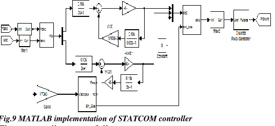
The STATCOM control strategy is shown in Fig.4. The controller works on the principle of PQ control theory. The reference voltage and current are taken from bus 10 (refer Fig.10); from these pa-rameters reference real and reactive powers are extracted. Using 1st order transfer function model, direct and quadrature axis cur-rents are derived from real and reactive powers.
The instantaneous real and reactive powers can be expressed
(41)
Q=[ ) ) ) ]
√ (42)
In two dimensional frame, the above equations can be represented as
(43)
(44)
In matrix form the two equations can be written as
[ ]=[ ] [ ] (45)
Or [ ]= [ ] [ ] (46)
By substituting the values of reference voltages and powers in equation (27), a first order transfer function can be obtained. This transfer function helps in extracting reference d and q axis cur-rents. If there is deviation in these reference currents, STATCOM will inject or absorb current to or from the system. Based on equations 17 and 18, the difference in currents will be supplied to the system. In Fig.5, X is reactance and K is instantaneous value
of voltage of STATCOM, E is the voltage at reference bus, Vd and
Vq are direct and quadrature components of STATCOM. The
transfer function is used to convert current to voltage parameters. Hence reference d and q axis reference voltage are derived. These d and q axis voltages are converted to three phase by using inverse Park’s transformation with the help of phase locked loop (PLL). Based on equation (13), voltage in capacitor is converted to cur-rent by STATCOM. In this equation α refers to voltage angle at
STATCOM bus and s is phase angle produced by PLL.
If the feedback is positive, STATCOM will inject current, else will absorb current from the system. The energy stored in DC link capacitor is used for injecting current into the system. This three phase voltages are given to PWM pulse generator to generate pulses to the IGBT module. Thereby voltage at reference bus can be maintained constant.
∑ ∑ P* Q* Ipd* Ipq* + + Vq* Vd* dq To abc PLL STATCOM parameters
Grid voltage in per unit -KX/E KX/E Vd/X TF Vd/X TF TF TF PQ Extraction (Vabc)(Iabc)* (Vabc) PWM
Pulse Generator STATCOM
Fig.8. Block Diagram of STATCOM controller
V. TIME DOMAIN SIMULATION
The design of test system shown in Fig.1 can be imple-mented in MATLAB and the model is shown in Fig.6. Gen1 and Gen2 represent generating stations in area1 and Gen3 and Gen4 in area2. Each generating station consists of synchronous generator with PSS and AVR with step up transformer. The Thevenin equivalent impedance of transmission network is represented with series RL elements. Two STATCOMs are connected to a common DC link capacitance with three winding transformers arrangement and a common pulse is shared by the two STATCOMs.
The transmission network is represented with equivalent nominal Π parameters. A symmetrical fault takes place at bus 8 as shown in Fig.5. The fault occurs at 0.2 seconds and cleared at 0.3. The control strategy for STATCOM is shown in Fig. 7. With volt-age and current parameters at bus 10, real and reactive powers are calculated. These powers are controlled independently by using transfer functions to derive direct and quadrature axis voltages as explained in section 3.
The direct axis voltage can control real power and quad-rature axis voltage will control the reactive power flow from STATCOM. The two phase voltages are converted into three phase (dq -abc) voltages and this reference voltage is fed to PWM converter to generate pulses to STATCOM. This controls the di-rection of current flow from STATCOM to system or vice-versa based on difference in voltage magnitude at reference point at STATCOM DC voltage. If at reference point, voltage is higher, current will flow to STATCOM and when at reference point are low, current flows from STATCOM. The voltage at reference point can be high due to Ferranti effect or sudden load throw off, lightning and voltage may decrease due to heavy loading or due to faults. The aim of STATCOM is maintain constant voltage magni-tude at reference point, minimise inter-area oscillations and to enhance stability and reliability.
P a g e | 5427
proposed controller and circuit design, voltage and currents of Gen1 and Gen3 in area1 and area2 are compared. Also, stator voltages and output power from generator is compared in all the cases. These two STATCOMs are connected at bus 7 in area1 to compensate voltage and to mitigate oscillations in area2. The pa-rameters of simulated model are given in Appendix. In this analy-sis, base voltage is taken as 230KV and current is 1500A.
Fig.9 MATLAB implementation of STATCOM controller
The case studies are as follows:
Case-1: without STATCOM.
In this case, STATCOM is not connected to the system and the results for bus voltage and current and machine parame-ters in area1 and 2 are given in Fig 10. The current is assumed to flow from area1 to area2 and severe fault occurs in area1 between buses 1 and 14. The results can be compared with references [10 and 11 without DVR case].
Fig 10a (i) shows voltage and current in pu values for ar-ea 1, (ii) arar-ea2 without STATCOM, and Fig.10b shows generator parameters in area1 and area2 respectively. Initially without fault, the voltage in both areas is 1 per-unit (pu) and current is 0.2pu in Gen1 and 0.4pu in Gen3. During fault, the voltage in area1 reach-es to nearly zero value and peak-peak current reachreach-es to 15pu, while in area2 voltage is 0.1pu and current is 17pu. Even though PSS and AVR are incorporated in the system, the system is unable to improve voltage during transient state, but was improved only when fault is relieved. Voltage surges are observed when fault was cleared at 0.3 seconds and voltages and currents got distorted and then come to steady state after long time.
Fig 10a (i) Voltage and current of Gen1 in area1 without STATCOM
Fig.10a (ii) Voltage and current of Gen3 in area2 without STATCOM
Fig 10b (i) Synch Gen1 stator voltage and rotor speed without STATCOM
Fig 10b (ii) Synch Gen3 stator voltage and rotor speed without STATCOM
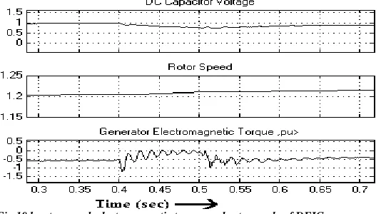
Fig 10d rotor speed, electromagnetic torque and rotor angle of DFIG
The generator behaviour during fault without STAT-COM can be analysed using Fig.10b. It can be observed that q axis components in two areas reach to 0.8pu from 1pu during fault and then start to oscillate and slowly damped out when fault was cleared. The output power from generator system which is initial-ly 0.2pu starts to oscillate when fault occurred. The oscillations also reached negative axis, implies there is to and fro current from generator. It is very unhealthy environment which makes the sys-tem to tumble and results in black-out. Hence there is a require-ment for STATCOM or such device to compensate surge currents and oscillations occurring in the generator-turbine system for healthy working conditions. DFIG current decreased to small val-ue as in Fig. 10c, but regains to pre-fault state earlier than SG an also torque, speed oscillations are less for DFIG as in Fig.10d.
Case-2: with single STATCOM
The system is studied with single STATCOM with fault is assumed to occur in the same place and at same time. The
sys-tem is analysed with same waveforms as explained in case-1 and
the waveforms are shown in Fig.11a and 11b.
It can be observed from Fig. 11a (i) and (ii), the voltages and current in area2 were mitigated completely although fault occurs in area1. It can be observed that, STATCOM can mitigate voltage dip and current surges in area1 to certain extent. In area1, voltage decreased from 1pu to nearly 0.5pu and current rises from 0.2pu to 0.55pu. Without STATCOM, the voltage dip is 0pu and 15pu. Fig.11b (i) for area1, the voltage in q-axis reached 0.8pu during fault and after fault oscillations were damped. But power oscillations in area1 are not damped during fault, but when fault was cleared, the system regains to its pre-fault state immediately.
Fig 11a (i) Voltage and current in area1 with single STATCOM
Fig 11a (ii) Voltage and current in area2 with single STATCOM
When examining in area2 generator parameters as shown in Fig.11b (ii), it can be observed that q and d-axis voltage re-mains almost constant during and post fault state and there has been no power oscillations. DFIG currents are shown in Fig.11c were decreased but having very less oscillations and is more sta-ble than SG. The Fig.11d depicts the voltage and current of STATCOM located at bus7 in area1. It can be observed that, STATCOM acts as low impedance path during fault and absorbs high surge current produced during fault. Due to this, surge cur-rent and voltage being observed during fault. This surge curcur-rent is stored in capacitor and reverted back the stored energy to com-pensate the voltage and current where it is referred.
P a g e | 5429
Fig. 11b (i) Generator parameters in area1 with single STATCOM
Fig. 11b (ii) Generator parameters in area2 with single STATCOM
Fig 11c (i) Rotor voltage and current of DFIG in area2 with STATCOM
Fig 11c (ii) rotor speed, electromagnetic torque and rotor angle of DFIG
Fig. 11d Voltage and current of STATCOM located at bus7
Case-3: with SSSC
The system is now tested with SSSC with fault is assumed to occur in the same place and at the same time. The system is
analysed with same waveforms as explained in case-1 and the
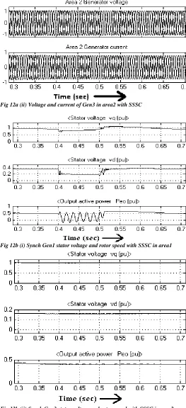
waveforms are shown in Fig.12a and 12b. It can be observed from Fig. 12a (i) and (ii), the voltages and current in area2 were mitigated completely and small sag can be observed in area1. It can be observed that, SSSC can mitigate voltage dip and current surges in area1 to certain extent and completely in area2 like STATCOM. In area1, voltage decreased from 1pu to nearly 0.5pu and current rises from 0.9pu to 2pu during fault. Without SSSC, the voltage dip is 0.1pu and current swell is15pu during fault while with SSSC in same area2 it is 0.56pu and 2pu. Fig.12b (i) for area1, the voltage in q-axis reached 0.8pu during fault and after fault oscillations were damped. But power oscillations in area1 are not damped during fault, but when fault was cleared, the system regains to its pre-fault state immediately. Area2 system is very stable with SSSC as per Fig.12b (ii).
Fig 12a (ii) Voltage and current of Gen3 in area2 with SSSC
Fig 12b (i) Synch Gen1 stator voltage and rotor speed with SSSC in area1
Fig 12b (ii) Synch Gen3 stator voltage and rotor speed with SSSC in area2
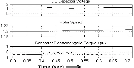
The rotor converter, grid converter and grid per unit (pu) current waveforms are shown in Fig.12c (i) and DC link capacitor voltage, rotor speed and electromagnetic torque are shown in Fig.12c(ii). SSSC voltage and current waveforms in pu in Fig.12d (i). It can be observed that stator and rotor urrent parameters re-mains nearly same before, during and after fault. Hence a little
reactive power support if given to DFIG, it can perform much better than synchronous generator.
Fig 12c (i) Rotor voltage and current of DFIG in area2 with SSSC
Fig 12c (ii) rotor speed, electromagnetic torque and rotor angle of DFIG
Fig 12d rotor speed, electromagnetic torque and rotor angle of DFIG (ii) volt-age injected by SSSC
P a g e | 5431
reference [11], proposed RSC-GSC control schemes for DFIG is better than this [11] for LVRT issues with same SSSC controller.
Case-4: with UPFC
For the same test system, UPFC is placed in between buses 4 and 14. The advantage of UPFC over STATCOM is, it has both STATCOM and SSSC, which are shunt and series devic-es. The rating of system is higher than single STATCOM and hence has much higher capability to mitigate the voltage dip and faster and effective to damp oscillations. SSSC is connected to-wards bus4 and STATCOM in bus14 in this study.
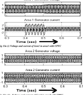
Fig 13a (i) Voltage and current of Gen1 in area1 with UPFC
Fig 13a (ii) Voltage and current of Gen3 in area2 with UPFC
Comparing Fig 10a (i) and 8a (i), voltage compensation is higher with UPFC than STATCOM for Gen1 in area1 as in Fig. 13a (i), (ii). With UPFC the voltage decreased from 1pu to 0.9pu, whereas with STATCOM, it is 0.5pu, but surge current is higher with UPFC as in Fig.11a(i), 12a(i) and 13a (i). It can be improved to much better voltage level with better control strategy for SSSC. For area2, the mitigation of voltage and current are same for both UPFC and STATCOM asin Fig. 11a(ii), 12a(ii) and 13a (ii).
Fig 13b (i) Synch Gen1 stator voltage and rotor speed with UPFC
Fig 13b (ii) Synch Gen3 stator voltage and rotor speed with UPFC
Fig 13c (ii) rotor speed, EM torque and rotor angle of DFIG with UPFC
Fig 13d SSSC voltage and current of UPFC circuit
From Fig.13b(i), the voltage decreased from 1pu to 0.9pu at the instant of fault and slowly regains to normal value even fault is not cleared. But when fault is cleared a surge voltage is produced due to sudden decrease in current flow. The power oscillations in area1 persist during fault and when fault is cleared, oscillations were damped quickly due to UPFC. From Fig. 13b (ii), the system behaves normally with or without fault. DFIG output currents as in Fig.13c (i) and machine parameters as in Fig.13c (ii) is nearly constant and are very stable and feels like it is having good fault through capability than SG.
The voltage across common capacitor link between the STATCOM and SSSC can absorb huge inrush current entering into the circuit. But when fault is released voltage across capacitor is increased. The SSSC converter pu voltage is shown in Fig.13d, it can be observed that huge currents are entering into SSSC circuit and voltage across SSSC was increased to nearly 7pu from 1pu. Similarly STATCOM current (not shown here) also in-creased to nearly 4.5pu times during fault. A higher rating VSC makes system more healthy and stable.
However UPFC is an excellent device which can regulate power flow in the line, decrease losses, improve power factor, regulate voltage margin and can damp effectively power oscilla-tions in the system. Disadvantages are design complexity, high capital investment for gate circuit, switches and high rating capac-itors and transformer bank. If power oscillations can be damped quickly and mitigate voltage sag and limit surge current for UPFC, it can be a much better device. Please refer [41] for comparison with proposed system.
Case-5: with Dual STATCOM
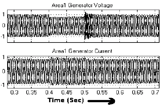
If only one STATCOM is placed, the surge current will pass through that STATCOM only. If another STATCOM is also connected in parallel but to reach current through other line as shown in Fig.1, if fault occurs between bus 4 and 17, it helps in sharing the surge current and relieves the IGBT switches and transformer from burden. Hence dual STATCOM is designed to bypass certain part of surge current to other STATCOM, as these devices acts as low impedance path for surge current. It can be observed from Fig.14a (i), the voltage in Gen1 in area1 decreases from 1pu to 0.903pu during fault and regains its post fault sate in less than1 cycle. Surge currents are diminished with this dual STATCOM arrangement. This proves the effectiveness of system compared to single STATCOM and UPFC.
In Fig.14a (ii) the voltage from Gen3 in area2 is initially 1.05pu and decreased to 1pu which is also within limits. If the receiving end is incorporated with automatic tap changing trans-former, the small dip in voltage can be compensated easily. Surge current was minimised throughout the system.
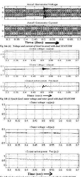
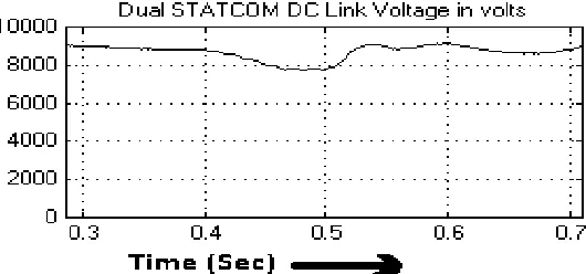
The generator parameters for Gen1 and Gen3 with dual STATCOM arrangement are shown in Fig.14b. The q-axis com-ponent voltages are nearly at 1pu and d-axis is at zero pu, which is as per requirement. There are few oscillations in d-axis compo-nents (Fig.14b(i,ii)) but can be neglected as this magnitude is very small compared to q-axis component and will not influence sys-tem performance during any state of operation. Due to fast action of STATCOM in regulating power flows, few oscillations in Gen1 are observed. These oscillations can be damped by choosing much higher rating of transformer and capacitor bank. The voltage across DC link capacitance is shown in Fig.14c. Under steady state capacitor voltage is near 1pu, but during fault this voltage is utilised to mitigate voltage sag and to damp oscillations, there is decrease in voltage. This voltage regains after fault is recovered.
P a g e | 5433
Fig 14a (ii) Voltage and current of Gen3 in area2 with dual STATCOM
Fig 14b (i) Synch Gen1 stator voltage and rotor speed with dual STATCOM
Fig 14b (ii) Synch Gen3 stator voltage and rotor speed with dual STATCOM
Fig14c (i) Rotor voltage and current of DFIG in area2 with dual STATCOM
Fig 14c (ii) rotor speed, EM torque and rotor angle of DFIG with dual STAT-COM
Fig 14d DC link Voltage across common capacitor for dual- STATCOM
If ratings of above said equipments increases, the second area stability can also get improved, but cost again increases. UPFC however is very costly due to usage of three single phase transformers for series compensating device, a high rating three phase step down transformer for shunt device and individual con-troller circuits, large floor area requirement to fix the setup, and technically complex operation. Hence UPFC is not better choice considering techno-economic benefits. To fix all power system issues, decrease rating of equipment and quantity of components, dual STATCOM is better choice. From economic point of view, transformer for dual STATCOM can be half rating of single STATCOM, sharing of common pulse is feasible. The propose STATCOM controller do not inject harmonics into the network, simple in design and rugged in construction.
From the above discussion DUAL STATCOM can be very good option in place of UPFC and other FACTS devices and much better option for DFIG or wind energy systems in order to maintain constant voltage profile and to enhance wind turbine-generator system stability. The overall cost of DUAL STATCOM is cheaper than UPFC and SSSC arrangement and also has ad-vantage of any time isolation as it is shunt converter. The DUAL STATCOM works nearly in the same principle of IPFC (Interline Power Flow Controller), but there is no need to have master and slave converters. For the present system a single pulse converter scheme was applied for both STATCOMs and found working very satisfactorily. It is also observed that at different fault loca-tions proposed DUAL STATCOM controller performance is much better than UPFC.
VI. IMPORTANT OBSERVATIONS
If a severe three phase to ground fault occur in the mid-point of the system, voltage in area1 and area2 will be dropped to zero or to a smaller value and the current will drastically increase (Fig.10a). It results in large oscillations in synchronous generator (SG) real power (Fig.10b) without FACTS controller. DFIG is having faster regaining from fault capability than SG. It can be observed with single STATCOM or SSSC; the oscillations in real power in one area can be completely damped and in other area can be stable (Fig.11b, 12b). The complete compensation of voltage and current in area2 is achieved and partial compensation in area1 can be observed (Fig.11a, 12a). The system regains its normal state after transients die out is due to the action of PSS and AVR and mostly due to STATCOM. If STATCOM or SSSC is not available, AVR or PSS fail to operate, this leads to instability and
may also cause the generator to damage if proper action is not
taken. In power stations, the relays will identify such situations and will trip the system from supplying power. This leads to load shedding and severe inconvenience to the customers. The effec-tiveness of single STATCOM can be improved by using UPFC. It can be observed that voltage mitigation in area1 is improved using UPFC (Fig.13a) than with STATCOM. Active output power oscil-lations are also damped quickly with UPFC (Fig.13b) and capaci-tor voltage is almost constant (Fig.13) which specifies the capabil-ity to mitigate more surge currents. However current surges in area1 are unable to control by UPFC and power oscillations are also not controlled during fault. This system is a better system compared to STATCOM with sacrifice in surge currents. If DFIG parameters are observed, with STATCOM, SSSC or UPFC as in Fig. 11c, 12c and 13c, rotor oscillations decreased in the same order with UPFC as much better device, however DFIG is much stable than SG. The performances when compared with different FACTS devices, dual STATCOM is much better with very less voltage dip in SG values, less harmonics or oscillations in DFIG, faster, simple in design, robust and cheaper.
VII. CONCLUSION
The dual STATCOM is designed in similar to that of single SATTCOM, but transformer ratings are made half by keep-ing same capacitor value. It is so as to divert some part of surge current into another STATCOM to make the system work much faster, self protection from inrush current. It is observed that volt-age mitigation is achieved and surge current is diminished in both areas (Fig.14a). The power oscillations are damped, q-axis voltage is maintained nearly at same value (Fig.14b). From all the above, dual STATCOM is much better device than UPFC or single SATTCOM. Many advantages proposed control circuit are, it is very simple in design and can be applied to low tension or high tension system. There are no decoupling components in control circuit, so effect on system parameters can be minimised. No need to calculate voltage across DC link capacitance, but STATCOM three phase voltage and current parameters are required. The cost incurred to design is much cheaper than UPFC and complexity of designing series and shunt compensators can be eliminated. It is more effective than UPFC in voltage regulation, power factor cor-rection and oscillations damping.
Appendix
Synchronous generator: Nominal Power- 200MW, nominal phase to phase voltage-13800V, frequency-60Hz, Xd-1.305, Xd1-0.296, Xd11-0.252, Xq-0.474, Xq1-0.243, Xq11-0.18.
Step-up Transformer: Nominal power rating 210MW, voltage rating- 13.8/230KV, internal resistance and reactance are 0.0027 and 0.08 per-unit(pu).
P a g e | 5435
DFIG Parameters: Pn=590MVA, Vph=690V, f=60Hz, Rs=0.049
pu, Lls=0.093pu, Rr1=0.0055pu, Llr=0.1pu, Lm=3.39pu,
H(s)=4.54pu, F(pu)=0.05479pu, pole pairs=4, DFIG transformer: Yg/Δ, 90MVA, 690/230KV
DFIG VSC: IGBT universal bridge with 80kMFD at back to back STATCOM Transformer: Pst=60MVA, V1=20/230KV
STATCOM common Capacitor: 10,000MFd.
VIII.REFERENCES
[1] Amara, S.; Hsan, H.A., “Power system stability improvement by FACTS de-vices: A comparison between STATCOM, SSSC and UPFC”, IEEE 2012 First International Conference on Renewable Energies and Vehicular Technology (RE-VET), Pp: 360 – 365.
[2] Griffo, A.; Lauria, D., “Some considerations on power system stability im-provement by FACTS devices”, IEEE SPEEDAM 2006. International Symposium on Power Electronics, Electrical Drives, Automation and Motion, 2006, PP: 809 – 813
[3] Kawabe, K.-i.; Yokoyama, A. , “Stability enhancement by multiple unified power flow controllers using wide-area information in the multi-machine power system”, IEEE 2010 International Conference on Power System Technology (POWERCON), Pp: 1 – 7
[4] Yuma, G.P.; Kusakana, K., “ Damping of oscillations of the IEEE 14 bus pow-er system by SVC with STATCOM”, 2012 11th Intpow-ernational Confpow-erence on Environment and Electrical Engineering (EEEIC),PP: 502 – 507
[5] Grunbaum, R. , “FACTS for voltage control and power quality improvement in distribution grids”, IET-CIRED. CIRED Seminar SmartGrids for Distribution, 2008, Pp: 1 – 4
[6] Kamarposhti, M.A.; Alinezhad, M.; Lesani, H.; Talebi, N., “Comparison of SVC, STATCOM, TCSC, and UPFC controllers for Static Voltage Stability evalu-ated by continuation power flow method”, IEEE Canada Electric Power Confer-ence, 2008. EPEC 2008, Pp: 1 – 8
[7] Hu Y.; Che Z., “STATCOM’s effects on stability improvement of induction generator based wind turbine systems”, Asia-Pacific Power and Energy Engineer-ing Conference, 2009. APPEEC 2009, PP: 1 – 4
[8] Safari Tirtashi, Mohammad Reza; Rohani, Ahmad; Noroozian, Reza, “PSS and STATCOM controller design for damping power system oscillations using fuzzy control strategies”, 2010 18th Iranian Conference on Electrical Engineering (ICEE), PP: 901 - 906
[9] Al-Ismail, F.S.; Abido, M.A., “The impact of STATCOM based stabilizers on Power System Stability, using intelligent computational optimization approach”, 2011 IEEE PES Innovative Smart Grid Technologies Asia (ISGT),
[10] Rai, D.; Faried, S.O.; Ramakrishna, G.; Edris, A. ,”Damping Inter-Area Oscil-lations Using Phase Imbalanced Series Compensation Schemes “, IEEE Transac-tions on Power Systems, Volume: 26 , Issue: 3, 2011, Pp: 1753 – 1761
[11] Ahmad Osman Ibrahim, Thanh Hai Nguyen, Dong-Choon Lee , Su-Chang Kim “A fault ride-through technique of dfig wind turbine systems using dynamic voltage restorers”, IEEE tran.on energy conv., vol. 26, no. 3, Sep 2011, pp:871-882 [12] Serhiy Bozhko, Greg Asher, Risheng Li, Jon Clare, Liangzhong Yao, “large offshore dfig-based wind farm with line-commutated HVDC connection to the main grid: engineering studies”, IEEE tran.on energy conv., vol. 23, no. 1, Mar 2008, pp:119-127
[13] Serhiy V. Bozhko, Ram´on Blasco-Gim´enez, Risheng Li, Jon C. Clare, Greg M. Asher, “control of offshore dfig-based wind farm grid with line-commutated HVDC connection”, IEEE tran.on energy conv., vol. 22, no. 1, Mar 2007, pp:71-78 [14] N. Senthil Kumar, J. Gokulakrishnan, “Impact of FACTS controllers on the stability of power systems connected with doubly fed induction generators”, Elec-trical Power and Energy Systems, Vol. 33, Mar 2011, PP: 1172–1184
[15] Lingling Fan, Chanxia Zhu, Zhixin Miao, Minqiang Hu, “modal analysis of a dfig-based wind farm interfaced with a series compensated network”, IEEE tran.on energy conv., vol. 26, no. 4, Dec 2011, pp:1010-1020.
[16] Wei Qiao, Ronald G. Harley, Ganesh Kumar Venayagamoorthy, “coordinated reactive power control of a large wind farm and a statcom using heuristic dynamic programming”, IEEE tran.on energy conv., vol. 24, no. 2, June 2009, pp:493-503. [17] Wei Qiao, Ganesh Kumar Venayagamoorthy, Ronald G. Harley, “Real-Time Implementation of a STATCOM on a Wind Farm Equipped With Doubly Fed Induction Generators”, IEEE trans. on ind. app, vol. 45, no. 1,Jan./Feb 2009, pp:98-107.
[18] Christian Wessels, Fabian Gebhardt, Friedrich Wilhelm Fuchs, “fault ride-through of a DFIG wind turbine using a dynamic voltage restorer during
symmet-rical and asymmetsymmet-rical grid faults”, IEEE tran, on pow. Elec., vol. 26, no. 3, Mar. 2011, pp:807-815
[19] Li Wang, Chia-Tien Hsiung, “dynamic stability improvement of an integrated grid-connected offshore wind farm and marine-current farm using a STATCOM”¸ IEEE tran. Pow. sys, vol. 26, no. 2, may 2011, PP:690-698
[20] Li Chun; Jiang Qirong; Xu Jianxin, “Investigation of voltage regulation stabil-ity of static synchronous compensator in power system”, IEEE Power Engineering Society Winter Meeting, 2000. Vol: 4, Pp: 2642 – 2647
[21] Suresh, Y.; Panda, A.K. , “Dynamic performance of STATCOM under line to ground faults in power system”, 5th IET International Conference on Power Elec-tronics, Machines and Drives (PEMD 2010),PP: 1 - 6
[22] P. Kundur, Power System Stability and Control, McGraw-Hill, 1994, Exam-ple 12.6, p. 813
[23] W. Eric Norum, K.E. Bollinger, “Lab and field tests of a self-tuning power system stabilizer”, IEEE Transactions on Energy Conversion, Vol. 8, No. 3, Sept. 1993, PP: 476-483.
[24] Sauer PW, Pai MA. Power system dynamics and stability, Pearson Education (Singapore); 2005.
[25] Nassif, A.B. ; da Costa, V.F. ; da Silva, L.C.P., “Effects of the SVC and the STATCOM on Damping Power Systems Low Frequency Electromechanical Oscil-lations”, IEEE Transactions on Latin America, Vol.2, No2, June 2004, PP: 120 – 125
[26] Fang, D.Z. ; Yuan, S.Q. ; Wang, Y.J. ; Chung, T.S., “Coordinated parameter design of STATCOM stabiliser and PSS using MSSA algorithm”, IET Generation, Transmission & Distribution, Vol: 1, No.4, 2007, PP:670-678.
[27] N.G. Hingorani and L. Gyugyi, Understanding FACTS; Concepts and Tech-nology of Flexible AC Transmission Systems, IEEE Press, New York, 2000, ISBN 0-7803-3455-8.
[28] F. Liu et al, “The Nonlinear Internal Control of STATCOM: Theory and Application”, International Journal of Electrical Power & Energy Systems, Vol. 25, Issue 6, 2003, pp. 421 – 430
[29] B.S. Rigby, N.S. Chonco and R.G. Harley, “Analysis of a Power Oscillation Damping Scheme Using a Voltage-Source Inverter”, IEEE Transactions on Indus-try Applications, Vol. 38, No. 4, July/August 2002, PP 1105-1113
[30] F.J. Swift and H.F. Wang, “Application of the Controllable Series Compensa-tor in Damping Power System Oscillations”, IEE Proceedings- Generation, Trans-mission and Distribution, Vol. 143, No. 4, July 1996, pp 359-364.
[31] S. Kannan, M.M.A., Shesha Jeyaram, Salama, “Real and reactive power coor-dination for a unified power flow controller”, IEEE Trans. Power Syst. Vol.19, August 2004, PP: 1454–1461
[32] K. Ravi Shanker, C. Nagamani, K. Shanti Swarup, “Investigations of UPFC for independent active and reactive power flow control, in: Proceedings of National Power Systems Conference NPSC-2004, December 2004, PP. 896–901.
[36] Larsen EV, Sanchez-Gasca JJ, Chow JH., “Concept for design of FACTS controllers to damp power swings”, IEEE Trans PWRS 1995;Vol.10, N0.2, PP:948–55.
[37] Yu YN. Electric power system dynamics. Academic Press; 1983.
[38] Noroozian M, Anderson G. “Damping of power system oscillations by use of controllable components”, IEEE Trans PWRD 1994, Vol.9, PP:2046–54
[39] Wang HF, Swift FJ. A, “ unified model for the analysis of FACTS devices in damping power system oscillations – Part-I: Single machine infinite bus power systems”, IEEE Trans PWRD 1997, Vol.2, PP:846–941.
[40] Farsangi MM, Song YH, Lee KY. Choice of FACTS devices control inputs for damping interarea oscillations. IEEE Trans Power Syst 2004;19(2):1135–43. [41] Pourbeik P, Gibbard MJ. “Damping and synchronizing torques induced on generators by FACTS stabilizers in multi-machine power systems”, IEEE Trans Power Syst 1996, Vol.11, PP: 1920–5.
[42] Al-Awami Ali T, Abdel-Magid YL, Abido MA. “A particle-swarm-based approach of power system stability enhancement with unified power flow control-ler”, Int J Electr Power Energy Syst, 2007, Vol.29, No.3, PP: 251–9.
[43] Tambey N, Kothari ML. “Unified power flow controller (UPFC) based damp-ing controllers for dampdamp-ing low frequency oscillations in power systems”. J Inst Eng, 2003, Vol.84, PP:35–41.
[44] Klein M, Rogers GJ, Kundur P. “A fundamental study of inter-area oscillation in power system”. IEEE Trans Power Sys 1991, Vol.6, No.3, PP:914–21. [45] Larsen EV, Swann DA. “Applying power system stabilizers, Part I, II, and III”, IEEE Trans Power Ap Syst 1981, Vol. 100, No.6, PP: 3017–46.