Available online:
http://edupediapublications.org/journals/index.php/IJR/
P a g e | 1428Analysis and Implementation of Parametric model of a
Piston rod
A.Uma Maheshwara Reddy1,G.Naresh Babu2, D.LokanaGouda3
1
M.Tech Scholar, Dept. of Mechanical, Siddhartha institute of technology and sciences, Telangana, India
2
Assistant Professor, Dept. of Mechanical, Siddhartha institute of technology and sciences, Telangana, India
3
Assistant Professor, Dept. of Mechanical, Siddhartha institute of technology and sciences, Telangana, India
Abstract:Connecting rod is the power transmission element which is used to transfer power form piston to the crank shaft in Internal Combustion Engine (IC
Engine).This paper describes modeling and
evaluationof connecting rod. In this task connecting rod ischanged with the assistance of Aluminum strengthened with Boron carbidefor Suzuki GS150R motorbike. A second drawing isdrafted from the calculations. A parametric model ofconnecting rod is modeled making use of professional-E5.0 software. Analysis is carried out by way of utilizing
ANSYSsoftware. Finite element analysis of
connecting rod iscarried out by using considering two substances, viz. Aluminumreinforced with Boron Carbide and Aluminum 360.The first-rate combo of parameters like Von missesstress and pressure, Deformation, aspect of defense andweight discount for two wheeler piston have been performed
inANSYS software. Compared to carbon
steel,aluminum boron carbide and aluminum
360,Aluminum boron carbide is found to have workingelement of security is nearer to theoretical component ofsecurity, 33.17% to shrink the load, to expand thestiffness by way of 48.55% and to diminish the stressby10.35% and most stiffer.
Keywords-Piston Rod, Crankshaft, Connecting Rod,PRO-E 5.0, ANSYS
I. INTRODUCTION
In a reciprocating piston engine, the connecting rod connects the piston to the crank or crankshaft. In modern automotive internal combustion engines, the connecting rods are most usually made of steel for production engines, but can be made of aluminum (for lightness and the ability to absorb high impact at the expense of durability) or titanium (for a combination of strength and lightness at the expense of affordability) for high performance engines, or of
cast iron for applications such as motor scooters. The small end attaches to the piston pin, gudgeon pin (the usual British term) or wrist pin, which is currently most often press fit into the con rod but can swivel in the piston, a "floating wrist pin" design. The connecting rod is under tremendous stress from the reciprocating load represented by the piston, actually stretching and being compressed with every rotation, and the load increases to the third power with increasing engine speed. Failure of a connecting rod, usually called "throwing a rod" is one of the most common causes of catastrophic engine failure in cars, frequently putting the broken rod through the side of the crankcase and thereby rendering the engine irreparable; it can result from fatigue near a physical defect in the rod, lubrication failure in a bearing due to faulty maintenance or from failure of the rod bolts from a defect, improper tightening, or re-use of
already used (stressed) bolts where not
recommended.
II. LITERATURE SURVEY
Pushpendra kumar Sharma et al. (2012) performed the static FEA of the connecting rod using the softwareand said optimization was performed to reduce weight. Weight can be reduced by changing the material of thecurrent forged steel connecting rod to crack able forged steel (C70). And the software gives a view of stressdistribution in the whole connecting rod which gives the information that which parts are to be hardened orgiven attention during manufacturing stage. [12]
Available online:
http://edupediapublications.org/journals/index.php/IJR/
P a g e | 1429 parametric model of connecting rod was modeledusing PRO-E 4.0 software.
Analysis was carried out by using ANSYS software. Finite element analysis of connecting rod was done byconsidering two materials, viz... Aluminum Reinforced with Boron Carbide and Aluminum 360. The bestcombination of parameters like Von misses stress and strain, Deformation, Factor of safety and weight reductionfor two wheeler piston were done in ANSYS software. Compared to carbon steel,
aluminum boron carbide andaluminum 360,
Aluminum boron carbide is found to have working factor of safety is nearer to theoretical factorof safety, 33.17% to reduce the weight, to increase the stiffness by 48.55% and to reduce the stress by10.35%and most stiffer. [7]
B. Anusha et al. (2013) compared the materials For Two-Wheeler Connecting Rod Using Ansys. In the analysistwo materials were selected and analyzed. The software results of two materials were compared and utilized fordesigning the connecting rod. By comparing the different results obtained from the analysis, it was concludedthat the stress induced in the structural steel was less than the cast iron. [3]
G. Naga Malleshwara Rao et al. (2013) carried out analysis of connecting rod using ANSYS. The mainObjective of the work was to explore weight reduction opportunities in the connecting rod of an I.C. engine byexamining various materials such as Genetic Steel, Aluminum, Titanium and Cast Iron. This was entailed byperforming a detailed load analysis. Therefore, the study has dealt with two subjects, first, static load and stressanalysis of the connecting rod and second. Design Optimization for suitable material to minimize the deflection.
In the first of the study the loads acting on the connecting rod as a function of time are obtained. The relationsfor obtaining the loads for the connecting rod at a given constant speed of crank shaft are also determined. Itcould be concluded from this study that the connecting rod could be designed and optimized under a comprisingtensile load corresponding to 360o crank angle at the maximum engine speed as one extreme load, and the
crankpressure as the other extreme load.
Furthermore, the existing connecting rod could be replaced with a newconnecting rod made of Genetic Steel. [6]
Kuldeep B et al. (2013) optimized connecting rod using alfasic composites. In the work connecting rod wasreplaced by aluminum based composite material reinforced with silicon carbide and fly ash. FEA analysis wascarried out by considering two materials. The parameter like von misses stress, von misses strain anddisplacement was obtained from ANSYS software. Compared to the former material the new material found tohave less weight and better stiffness. It resulted in reduction of 43.48% of weight, with 75% reduction indisplacement. [8]
Ambrish Tiwari et al. (2014) presented the paper for connecting rod Finite Element Analysis for weight andcost reduction opportunities for a production of forged steel connecting rod. It was also performed a fatiguestudy based on Stress Life (SxN) theory, considering the Modified Goodman diagram. [2]
Table.1 shows the specifications of the connecting rod for carbon steel (Suzuki GS). The typical chemical composition of the material is 0.61%C, 0.095% Al, 0.82%Mn, 0.00097%Br, 0.145% C, 7.8Co, 75.56Fe and 3.25 Mo.
Available online:
http://edupediapublications.org/journals/index.php/IJR/
P a g e | 1430 III. THEORETICAL CALCULATIONSOFPISTONROD
A connecting rod is a machine member which is subjected to alternating direct compressive and tensile forces. Since the compressive forces are much higher than the tensile force, therefore the cross-section of the connecting rod is designed as a strut and the Rankin formula is used. A connecting rod subjected to an axial load W may buckle with x-axis as neutral axis in the plane of motion of the connecting rod, {or} y-axis is a neutral axis. The connecting rod is considered like both ends hinged for buckling about x-axis and both ends fixed for buckling about y-axis. A connecting rod should be equally strong in buckling about either axis.
LetA = cross sectional area of the connecting rod. L = length of the connecting rod.
C = compressive yield stress. Wcr = crippling or buckling load.
Ixx = moment of inertia of the section about x-axis Iyy = moment of inertia of the section about y-axis respectively.
Kxx = radius of gyration of the section about x-axis
Kyy = radius of gyration of the section about y- axis respectively.
D = Diameter of piston r = Radius of crank
A. PRESSURE CALCULATION FOR 150CC ENGINE Suzuki GS 150 R
Specifications
Engine type air cooled 4-stroke Bore × Stroke (mm) = 57×58.6
Displacement = 149.5CC
Maximum Power = 13.8bhp@8500rpm Maximum Torque = 13.4Nm@6000rpm Compression Ratio = 9.35/1
Density of Petrol C8H18 = 737.22kg/m3 = 737.22E-9kg/mm3
Temperature = 60F = 288.855K
Mass = Density × Volume = 737.22E-9×149.5E3 = 0.11Kg
Molecular Weight of Petrol 114.228 g/mole From Gas Equation,
PV=Mrt R = R*/Mw = 8.3143/.114228 = 72.76 P = (0.11x72.786x288.85) / 149.5E3 P = 15.469 Mpa.
B. DESIGN CALCULATION FOR CARBON STEEL
Thickness of flange & web of the section = t Width of B= 4t
The standard dimension of Height of section H = 5t Area of section A= 2(4t×t) +3t×t
A = 11t²
M.O.I of section about x axis: I xx = 112 [4 {5 }3−3 {3 }3] = 41912[ 4]
MI of section about y axis: Iyy = 2×112×t×{4t}3+112{3t}t3 = 13112[t4]
IxxIyy = 3.2
Length of connecting rod (L) = 2 times the stroke L = 117.2 mm
Buckling load WB = maximum gas force × F.O.S
WB = ( × )(1+a (L/Kxx)2
= 37663N
= compressive yield stress = 415MPa K xx = I xxA
K xx = 1.78t
a = 2
a = 0.0002
By substituting , A, a, L, Kxx on WB then
Available online:
http://edupediapublications.org/journals/index.php/IJR/
P a g e | 1431 t2 = 10.03t = 3.167mm t = 3.2mm
Width of section B = 4t = 4×3.2
= 12.8mm
Height of section H = 5t = 5×3.2
= 16mm Area A = 11t2 =11×3.2×3.2 = 112.64mm2
Height at the big end (crank end) = H2 = 1.1H to 1.25H
= 1.1×16 H2 =17.6mm
Height at the small end (piston end) = 0.9H to 0.75H
= 0.9×16 H1 =12mm
C. 2D Drawing for Connecting Rod Stroke length (l) =117.2mm Diameter of piston (D) =57mm Stroke length (l) =117.2mm Diameter of piston (D) =57mm P=15.5N/mm2
Radius of crank(r) =stroke length/2 =58.6/2
=29.3
Maximum force on the piston due to pressure Fl = π4xD2xp
=π/4 x (57)2x15.469 =39473.16N
Maximum angular speed Wmax= [2πNmax]60
= [2π×8500]60 = 2
=768 rad/sec
Ratio of the length of connecting rod to the radius of crank
N= lr =112/ (29.3) = 3.8
Maximum Inertia force of reciprocating parts F im = Mr (Wmax) 2 r (cosθ + COS2θn) (Or) F im = Mr (Wmax)2 r (1+1n)
= 0.11x (768)2 x (0.0293) x (1+ (1/3.8)) F im = 2376.26N
Inner diameter of the small end d1 = ×
= 6277.16712.5×1.5d1 = 17.94mm
Where,
Design bearing pressure for small end pb1=12.5 to 15.4N/mm2
Length of the piston pin l1= (1.5to 2) d1 Outer diameter of the small end = d1+2tb+2tm = 17.94 + [2×2] + [2×5]
= 31.94mm Where,
Thickness of the bush (tb) = 2 to 5 mm Marginal thickness (tm) = 5 to 15 mm Inner diameter of the big end d2= FgPb2 ×l2 = 6277.16710.8×1.0d1
=23.88mm Where,
Design bearing pressure for big end pb2 = 10.8 to 12.6N/mm2
Length of the crank pin l2 = (1.0 to 1.25) d2 Root diameter of the bolt = ( (2Fim)(πxSt))1/2 = (2×6277.167π×56.667)1/2
= 4mm
Outer diameter of the big end = d2 + 2tb + 2db +2tm
= 23.88+2×2+2×4+2×5 = 47.72mm
Where,
Thickness of the bush [tb] = 2 to 5 mm Marginal thickness [tm] = 5 to 15 mm
Nominal diameter of bolt [db] = 1.2 x root diameter of the bolt
= 1.2×4 = 4.8mm
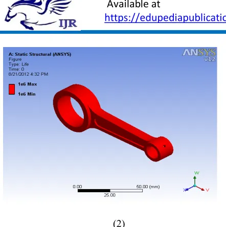
IV. STEPSINMODELINGOF CONNECTINGROD
Available online:
http://edupediapublications.org/journals/index.php/IJR/
P a g e | 1432 CAD Model of connecting rod in PRO Engineer.The following is the list of steps that are used to create the required model:
1. Choose the reference plane.
2. Set the dimension in mm.
3. Go to sketcher and sketch circular entities. 4. Then extrude these entities for making the
both ends of connecting rod.
5. Again reference plane is selected for shank of connecting rod.
6. Entities is made that should be tangential to both ends.
7. Extrude the entities symmetrically.
8. Plane is selected for making entities of groove.
9. Groove is made on the shank and mirrored for creating groove on both side.
10. Datum plane is selected for creating small holes on piston end then holes are made on the periphery of piston end.
V. ARESULTS OF FINITE ELEMENT ANALYSISANDCOMPARISION WITH
EXISTINGRESULTS
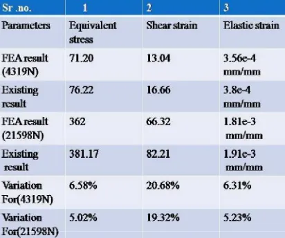
In this study four cases of finite element models are analyzed. FEA for both tensile and compressive loads are conducted. Two cases are analyzed for each case, one with load applied at the crank end and restrained at the piston pin end, and the other with load applied at the piston pin end and restrained at the crank end. In the analysis carried out, the axial load was 4319 N (Gas Force) in both tension and compression. In addition to this the analysis carried out taking Buckling Load of 21598N. Finally the comparisons are done for optimization purpose.
The pressure constants for 4319 N are as follows used for applying Boundary Condition:
Compressive Loading:
Crank End: Po = 4319/ (17.5 x 10.708 x _3) = 13.31 MPa
Piston pin End: Po = 4319/ (7.8 x 14 x _3) = 22.84 MPa
Tensile Loading:
Crank End: Po = 4319/ [17.5 x 10.708 x (_/2)] = 14.68 MPa
Piston pin End: Po = 4319/ [7.8 x 14 x (_/2)] = 25.18 MPa
Following are Figures shows the optimized results along with the results of figures in reference paper and comparison for static analysis of connecting rod at load 4319N.
Above figures shows the comparison equivalent von misses stress at 4319N.
Available online:
http://edupediapublications.org/journals/index.php/IJR/
P a g e | 1433 Above figures shows the comparison of equivalentelastic strain at 4319N
Table shows the result comparison for static analysis
Following are Figures shows the optimized results along with the results of figures and comparison for static analysis of connecting rod at load 21598N.
Above figure shows the comparison of safety factor at 4319N.
Above figure shows the comparison of safety factor at 21598N.
Above figure shows the comparison of safety factor at 21598N.
Following are Figures shows the optimized results along with the results of figures in reference paper and comparison for fatigue analysis of connecting rod at load 21598N.
Available online:
http://edupediapublications.org/journals/index.php/IJR/
P a g e | 1434 (2)Above (1) and (2) figures shows the life at 4319N and 21598N
(3)
(4)
Above (3) and (4) figures shows the damage at 4319N and 21598N.
Table shows the comparison of Weight
Above table shows the weight optimization of connecting rod, in existing model weight of connecting rod was 131.5g. After optimization weight of connecting rod is126.73, the percentage weight reduction is 3.62.
VI. CONCLUSION
Finite element analysis of the connecting rod of aSuzuki GS150R has been finished using FEA deviceANSYS Workbench. From the outcome received fromFE evaluation, many discussions had been made. Theresults got are well in agreement with theequivalent available current consequence. The modelprovided right here, is good trustworthy and below permissiblerestrict of stresses.
1. Conclusion is based on the current work that thedesign parameter of connecting rod with changeoffers ample development in the present results.
2.The burden of the connecting rod can also be lowered by0.477g. Thereby, reduces the inertia force.
3.Fatigue strength is the principal drivingfactor for the design of connecting rod and it's determinedthat the fatigue results are in good agreement with thepresent outcomes.
4.The stress is determined maximum on the piston finish sothe material is improved within the stressed portion toshrink stress.
REFERENCES
Available online:
http://edupediapublications.org/journals/index.php/IJR/
P a g e | 1435 forged steel and PM connecting rods". SAETechnical Paper, 1: 1529.
[2] Anonymous, 2008. "Nissan Z24engine
Maintenance and Repayments catalogue".
Megamotor Co
[3] B. Anusha, C.Vijaya Bhaskar Reddy “Modeling and Analysis of Two Wheeler Connecting Rod by UsingAnsys” ISSN: 2320-334X, Vol. 6, Issue 5, May. - Jun. 2013
[4] Dr. B.K.Roy. “Design Analysis and Optimization of
Various Parameters of Connecting Rod using
CAESoftwares” ISSN: 2319-6319, IJNIET, Vol. 1, Issue 1, October 2012.
[5] Fanil Desai, Kiran kumar Jagtap, Abhijeet Deshpande “Numerical and Experimental Analysis of ConnectingRod” ISSN 2349-4395, IJEERT, Vol. 2, Issue 4, July 2014.
[6] G. Naga Malleshwara Rao “Design Optimization and Analysis of a Connecting Rod using ANSYS” ISSN:2319-7064, IJSR, Vol. 2 Issue 7, July 2013.
[7] K. Sudershn Kumar, Dr. K. Tirupathi Reddy, Syed Altaf Hussain “Modeling and Analysis of Two WheelerConnecting Rod” ISSN: 2249-6645, IJMER, Vol 2, Issue 5, Sep-Oct. 2012.
[8] Kuldeep B, Arun L.R, Mohammed Faheem “Analysis
and Optimization of Connecting Rod Using
AlfasicComposites” ISSN: 2319-8753, IJIRSET, Vol. 2, Issue 6, June 2013.
[9] Mr. J.D. Ramani, Prof. Sunil Shukla, Dr. Pushpendra Kumar Sharma. “FE-Analysis of Connecting Rod ofI.C.Engine by Using Ansys for Material Optimization” ISSN: 2248-9622, IJERA, Vol. 4, Issue 3, Version1, March 2014.
[10] P.S. Shenoy and A Fatemi “Dynamic analysis of loads and stresses in Connecting Rods” JMES105, Vol.220 Part C, 2006.
[11] Prateek Joshi, Mohammad Umair Zaki “FEM Analysis of Connecting Rod of different materials usingANSYS” ISSN: 2395-1303, IJET, Vol. 1, Issue 3, May - June 2015.
[12] Pushpendra Kumar Sharma, Borse Rajendra R “Fatigue Analysis And Optimization Of Connecting RodUsing Finite Element Analysis” ISSN-2319-8354, IJARSE, Vol. No.1, Issue No. I, September 2012.
[13] R.A. Savanoor, Abhishek Patil, Rakesh Patil, Amit Rodagi “Finite Element Analysis Of IC EngineConnecting Rod By Ansys” ISSN: 2278 – 0149, IJMERR, Vol. 3, No. 3, July 2014.
[14] Sushant, Victor Gambhir “Design and Comparative Performance Analysis of Two Wheeler ConnectingRod Using Two Different Materials Namely Carbon 70 Steel and Aluminum 7068 by Finite ElementAnalysis” ISSN: 2321-3051, IJRAME, Vol. 2, Issue. 6, June 2014.
BIODATA
AUTHOR1
A.Uma Maheshwara Reddy has pursuing M.Tech (Thermal Engineering) from Siddhartha Institute of Technology and Sciences, Ghatkesar, Rangareddy, Telangana, India.
AUTHOR2
G.NareshBabu has presently working as Assistant Professor and HoD of Mechanical Department in Siddhartha Institute of Technology and Sciences, Ghatkesar, Rangareddy, Telangana, India.
AUTHOR3