Automatic Load Sharing of Transformers
using Microcontroller
T.Venkata Sai Kalyani1, V.Sunil Kumar 2, Ch.Srinivas3
Assistant Professor, Department of EEE, St.Martin’s Engg. College, Hyderabad, TS, India1 Associate Professor, Department of EEE, St.Martin’s Engg. College, Hyderabad, TS, India2, 3
ABSTRACT: The transformer is a static device, which converts power from one level to another level. The aim of the project is to protect the transformer under overload condition by load sharing. Due to overload on transformer, the efficiency drops and windings get overheated and may get burnt. Thus by sharing load on transformer, the transformer is protected. This will be done by connecting another transformer in parallel through a micro-controller. The micro controller compares the load on the first transformer with a reference value. When the load exceeds the reference value, the second transformer will share the extra load. Therefore, the two transformer work efficiently and damage is prevented. In this project three modules are used to control the load currents. The first module is a sensing unit, which is used to sense the current of the load and the second module is a control unit. The last module is micro-controller unit and it will read the analogue signal and perform some calculation and finally gives control signal to a relay. A GSM modem is also used to inform the control station about switching. The advantages of the project are transformer protection, uninterrupted power supply, and short circuit protection. When designing low-voltage power system to the supply large load currents, paralleled lower-current modules are often preferred over a single, large power converter for several reasons. These include the efficiency of designing and manufacturing standard modular converters which can be combined in any number necessary to meet a given load requirement and the enhanced reliability gained through redundancy.
KEYWORDS: Transformer Overload, Microcontroller, Uninterrupted Power Supply.
I. INTRODUCTION
is all about protecting the transformer under overload condition. This can be done by connecting another transformer in parallel through a microcontroller and a relay which shares the excess load of the first transformer. The transformers are switched alternatively to avoid thermal overloading. Therefore, two transformers work efficiently under overload condition and damage can be prevented. If there is a further increase in load beyond the capacity of two transformers there will be a priority based load shedding of consumers which will provide un-interrupted power supply for the hospitals, industries etc.
II. RELATED WORK
In the power system transformers may be loaded beyond their nameplate ratings due to a fault or some emergency conditions. This type of overloading can cause either short term failures or long term failures. Increase in hot spot temperature would also lead to the accelerated ageing of the transformers resulting in transformer overload. So in order to keep the body temperature of the transformer within its nameplate rating, the transformer must be loaded efficiently in a controlled manner.
Our system aims at load sharing of transformers and priority based load shedding. The procedure of load sharing is summarised below.
1. Loads are supplied from a single transformer under normal condition and a standby transformer is connected in parallel through a circuit breaker.
2. A current transformer measures the load current continuously and feeds it to the controller by converting it to a corresponding D.C value in order to compare with the reference value set by the user.
3. Whenever the load current exceeds reference value, the controller sends a high signal to the relay which energises the relay coil. The relay coil thus sends a tripping signal to the circuit breaker of the standby transformer.
4. Thus the load is shared by the transformers equally as the transformers are identical. The current transformer still measures the load current and compares it with the reference value.
5. Whenever the load current falls below reference value one transformer is shut down and this is done in an alternative manner to avoid thermal overloading.
6. If the load value increases further beyond the capacity of two transformers, load will be cut-off from the main supply based on the priority level set by the user. This is done to provide un-interrupted power supply to higher priority loads.
7. Each of the process is informed to the controller by a GSM and the load parameters are continuously displayed in the LCD.
III. BLOCK DIAGRAM
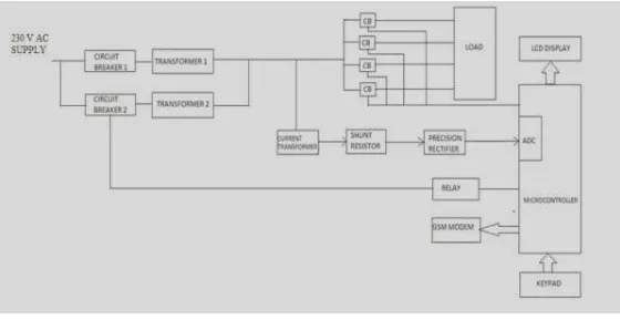
Figure 3.1 shows the block diagram of automatic load sharing of transformers using microcontroller. The various components in the system are described below.
Fig 3.1 Block Diagram
In the block diagram circuit breakers are used to make and break the connections to the transformers. A relay is used to send a tripping signal to the circuit breakers and they are energised on receiving a signal from the microcontroller. The current transformer is used for measurement purpose.
Circuit breaker
A circuit breaker is used to isolate the faulty point of the power system in case of abnormal conditions such as faults. It is a protective device which energizes and de-energizes a circuit and provides over-current protection. Circuit breakers operate on receiving a signal from relay.
Transformers
A transformer is an electrical device that transfers electrical energy between two or more circuits through electromagnetic induction Transformers convert AC voltage from one level to another level with a little loss of power. A transformer operates on the principals of “electromagnetic induction”, in the form of mutual induction. The transformer used here is a step-down transformer so that it can be directly fed to the measuring devices by rectification.
Microcontroller
The microcontroller is used to compare the load current with reference value. Atmega328 is the controller used for this purpose and it also provides a provision for GSM module and in built ADC.
Relay
IV. SYSTEM DESCRIPTION
The system consists of microcontroller, transformers, circuit breakers, relay, Current Transformer (CT), GSM modem and LCD display. The transformers are step down transformers in which only one transformer is operating under normal condition. The input to the transformer is fed through a circuit breaker to which a relay is connected. The circuit breaker is in closed position for transformer which is operating. Here the transformer feeds five loads which are provided with individual circuit breakers for protection. A stand by transformer is connected in parallel to the main transformer through a circuit breaker. In order to measure the current through the transformer a current transformer is connected to the secondary of the operating transformer. The current transformer measures the load current continuously and is fed to the microcontroller through a rectifier circuit. The output from the current transformer can also be fed directly to inbuilt ADC pins of controller, instead of using a rectifier. A GSM connected to the controller enables communication between the system and control room. The maximum load limit is entered to the controller through a keypad and a LCD display gives an indication of the same. The microcontroller continuously compares the CT value with the maximum limit entered. Whenever the current exceeds the maximum limit, the main transformer gets overloaded and the second transformer shares the total load equally. At the same time the GSM sends a message to the control room. When there is a further increase in load beyond the rated capacity of two transformers, microcontroller will give control signal to the circuit breaker of respective load to open, based on the priority level set by the user. When the load decreases and comes to normal value which is less than the maximum limit, the first transformer will shut down automatically. This type of alternative switching method avoids the possibility of thermal overloading by providing enough time for the transformer to cool naturally. Each time the transformer is overloaded or switched a message is sent to the control room about the mode of operation. Thus it enables efficient operation of existing transformer and provides un-interrupted power supply to hospitals, industries and other important areas.
Operating principle
V. CIRCUIT DIAGRAM
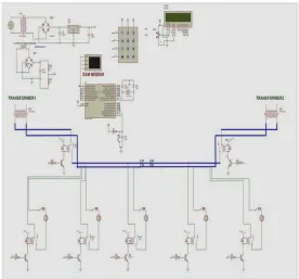
The circuit diagram of the proposed system is shown in figure 5.1. Here two transformers share 5 loads which can be controlled independently.
Fig 5.1 Circuit Diagram of Automatic Load Sharing of Transformers using Microcontroller
Circuit Diagram Description
Connections
The controller used is ATmega 328 which is 8 bit controller and has 20 I/O pins of which there are 14 digital I/O pins and 6 analog pins. The keypad is configured as rows and columns of which either row or column is set as input. Thus the controller reads the value by matrix arrangement. Crystal oscillator is connected to pin no. 9 and 10 of the controller which generates clock signals. Digital pins PD0 to PD7 are configured as output and all the output devices like LCD and GSM are interfaced to this port. The row pins of the keypad and the relay is connected to the port B while the column pins of keypad and CT is connected to port C of the controller. All the loads are connected to the port B through a relay which is supplied with a 12V supply. Relay contacts are shown named as RLY 1, RLY 2, and RLY 3. Of these two relay contacts corresponds to two transformers and the third relay corresponds to priority based load shedding. A crystal oscillator is used to generate clock signals to the controller. It is also possible to use internal oscillator of the controller unless the ADC pins are used. A CT is connected to ADC pin 5 of the controller and a variable resistor is used to vary the value of CT. A GSM is connected to digital pins 0 and 1for communication purpose. In order to view the message displayed by GSM, a virtual terminal is used. A 4x3 keypad is used to set the maximum load limit and the LCD gives a visual indication of CT value and maximum load limit. For LCD display four bits of address lines are connected to the controller. RESET pin is connected to the power supply so that the controller works continuously. The controller can be reset by applying a logical low signal to RESET pin. Relays are connected with transistors which act as switches. Whenever a high signal is applied to the base of the transistor, the transistor act as a closed switch and energizes the coil of the relay which in turn latches the relay contactors. A freewheeling diode or a flywheel diode is connected across the relay coil to protect the collector terminal of transistor from the back emf of the relay coil.
VI. EXPERIMENTAL RESULTS
Hardware implementation of the Automatic Load Sharing of Transformers using Microcontroller was developed using Atmega328 microcontroller.
Simulation was done in PROTEUS ver. 7.7 and the output was verified.
Priority based load shedding provided un-interrupted power supply to certain loads like hospitals
load is shared by the transformers equally since the transformers were of same rating
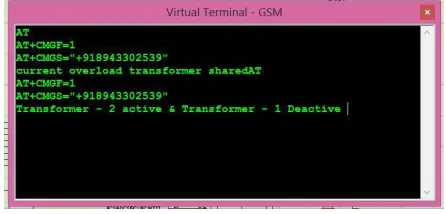
The message sent by the GSM was viewed by a Virtual terminal in PROTEUS as shown below.
Fig 6.1 Virtual Terminal of a GSM
VII. CONCLUSION
connecting transformers in parallel. In this project of Automatic Load Sharing of Transformers Using Microcontroller, a technology is implemented to share the load on the transformers. This provides un-interrupted power supply and avoids blackout in particular areas where there is varying loads. With the advancement of communication technology, now it is possible to receive overload condition of transformer through GSM to the control room. During overload condition exceeding specified limits information is immediately communicated through GSM technology to the concerned authority for possible remedial actions. Hence the transformer is protected from the overload condition and uninterrupted power supply is available to the consumers.
REFERENCES
[1]. S.R.Balan, P.Sivanesan, R.Ramprakash, B.Ananthakannan and K.MithinSubash,“ GSM Based Automatic Substation LoadShedding and Sharing Using Programmable Switching Control”, Journal of Selected Areas in Microelectronics, Volume 6, Issue 2, pp. 59-61, 2014.
[2]. Ashish R. Ambalkar, Nitesh M. Bhoyar, Vivek V. Badarkhe and Vivek B. Bathe, “Automatic Load Sharing of Transformers”, International Journal for Scientific Research & Development, Volume 2, Issue 12, pp. 739-741,2015.
[3]. Rekha.T,BinduPrakash, Asna. S, Dinesh.S and Nandana.S.Prasad, “An Intelligent Method for Load Sharing of Transformers With
[4]. Temperature Monitoring and Automatic Correction of Power Factor”, International Journal Of Engineering Sciences & Research Technology, Volume 4, Issue3, pp. 416-421, 2015.
BIOGRAPHY
T.V.Sai Kalyani, Completed M.Tech at G.Narayanamma Institute of Technology & Sciences for Women, Autonomous Under JNTUH, Telangana, India. She received her B.Tech. degree from Geethanjali College of Engineering And Technology, JNTUH, Keesara, TELANGANA. Currently she is working as Assistant Professor in the Department of EEE at St.Martin’s Engineering College, Dhulapally, Secunderabad, Telangana. Her interests include in the areas of Power Electronics and Drives and Renewable energy sources.
V. SUNIL KUMAR, Associate Professor in EEE, completed B.Tech in Electrical & Electronics Engineering from Syed Hashim College of Science and Technology Affiliated to JNTU Hyderabad and M.Tech in Electrical Power Systems from B.S.A.Crescent Engineering College affiliated to Anna University, Chennai. He is working as Associate Professor in St. Martin‟s Engineering College,
Dhullapally, Secunderabad, Telangana. His Area of interest includes Power Systems, FACTS Devices and Renewable Energy Systems. He is the life time member in Indian Society for Technical Education (ISTE).
CH. SRINIVAS is currently working as an associate professor in St.Martin’s Engineering College,