1
CONTRACT NUMBER N00164-94-C-0040
SW370-BD-OPI-010
Operator’s
Manual
Mark
23
Pistol,
Semi-automatic,
Caliber
.45
ACP
© Heckler & Koch, Inc., October 1996
21480 Pacific Blvd.
Sterling, Virginia 20166-8903
United States of America
Telephone (703) 450-1900
®
WARNING
A
firearm
has
the
capability
of
taking
your
life
or
the
life
of
someone
else!
Be
extremely
careful
with
your
firearm.
An
accident
can
occur
at
anytime
and
is
almost
always
the
result
of
not
following
basic
safety
2
TABLE OF CONTENTS
PAGE CHAPTER 1 INTRODUCTION ... ... 4 SECTION I GENERAL INFORMATION ... ... 4 SECTION II PISTOL DESCRIPTION ... ... 6
1.2 Nomenclature
...
.6
1.3 Principle of Operation
...
7
1.4 Major Assembly Groups
...
7
1.5 Technical Specifications
... 9 CHAPTER 2 OPERATING INSTRUCTIONS ... 1 0 SECTION I
SERVICE UPON RECEIPT OF MATERIAL
...
1
0
2.1 Initial Inspection
... 1 0 SECTION II GENERAL DESCRIPTION ... ... 1 0
2.2 Description
...
...
1
0
2.3 Operation and Characteristics
...
1
1
2.4 Cycle of Operation
...
1
3
2.5 Safety Features
...
1
7
SECTION III
OPERATION UNDER NORMAL CONDITIONS
...
1
8
2.6 Clearing Procedures
...
1
8
2.7 Loading and Unloading the Magazine
...
1
9
2.8 Loading Procedure
...
2
0
2.9 Readying the Pistol for Firing
...
2
1
2.10 Firing the Pistol
...
2
2
SECTION IV
OPERATION UNDER UNUSUAL CONDITIONS
...
2
3
2.11 Extreme Cold
...
2
3
2.12 Hot, Wet Climates
...
2
3
2.13 Hot, Dry Climates
...
2
4
2.14 Heavy Rain and Water Operations - All Climates
...
2
3
SECTION V
MALFUNCTIONS AND STOPPAGES
...
2
5
2.15 Remedial Action
...
2
5
CHAPTER 3
MAINTENANCE INSTRUCTIONS
...
2
7
SECTION I
TOOLS & EQUIPMENT
...
...
2
7
3.1 Operator Tools and Equipment Required
...
2
7
SECTION II
PMS CHECKS & MAINTENANCE PROCEDURES
...
2
7
3.2 General
...
...
2
7
3.3 Disassembly (Field stripping)
...
2
8
3.4 Reassembly (From field strip)
...
3
0
3.5 Safety/Function Check
...
3
3
3.6 Function Firing
...
3
6
3.7 Cleaning
...
...
3
6
3.8 Inspection
...
....
3
7
3.9 Lubrication
...
...
3
8
SECTION III
ADJUSTMENT OF SIGHTS
...
..
4
0
SECTION IV
TROUBLESHOOTING PROCEDURES
...
4
3
3.10 Operator Troubleshooting Procedures
...
4
3
3.11 Parts Listing and Exploded Diagram
...
4
6
CHAPTER 4
AMMUNITION
...
...
4
8
FIREARM SERVICE RECORD
...
4
CHAPTER 1 INTRODUCTION
SECTION I - GENERAL INFORMATION
The HK Mark 23 .45 ACP pistol give shooters match
grade accuracy equal to that of the finest custom made
handguns
—
yet it exceeds the most stringent operational
requirements ever demanded of a combat handgun.
The Mark 23 provides this accuracy without the need for
hand-fitted parts common in custom-built match pistols
costing thousands of dollars more. Repair of the Mark 23
is reduced to a simple parts exchange.
The HK Mark 23, is a commercial model of the U.S.
Government issue MK 23, MOD 0 pistol and is available
in limited numbers. Designated the
“Mark 23
”, it is almost
identical to the MK 23, MOD 0 pistol used by the Special
Operations Command, right down to its threaded barrel.
The main differences are slide Markings (Mark 23 as
opposed to MK 23) and a barrel manufactured to SAMMI
headspace specifications.
One of the most thoroughly tested handguns in history,
the MK23/Mark 23 project originated in 1991 when HK
was awarded a development contract for the Special
Operations Forces Offensive Handgun Weapon System,
consisting of a caliber .45 pistol, detachable sound and
flash suppressor, and laser aiming module (LAM).
During testing, MK 23 pistols met the most stringent
operational and accuracy requirements ever demanded of
a combat handgun. MK 23 pistols achieved match grade
accuracy of less than a 2.5 inch maximum extreme
spread in 5-round shot groups at 25 meters with service
ammunition. Endurance testing demonstrated a service
life of over 30,000 rounds of +P ammunition with no parts
breakage, with an additional 30,000 rounds certified on
the slide and frame.
To meet the reliability requirement, the pistol had to
demonstrate a minimum of 2,000 mean rounds between
stoppages (MRBS) with both M1911 ball and +P
ammunition. The minimum MRBS achieved in testing was
6,027 and the maximum was 15,122!
During over 450 accuracy test firings from a precision
firing fixture, MK 23 pistols far exceeded the government
requirement, averaging 1.44 inches, with 65 groups of
less than one inch. There were four groups of .5 inches,
with 5 rounds going through the same hole! This included
firing with and without the sound/flash suppressor
5
Three pistols were tested for accuracy after firing over
30,000 rounds, the specified service life of the pistol, and
still met the new pistol accuracy requirement. An
innovative design feature, a high temperature rubber
O-ring on the barrel that seals the barrel in the slide until
unlocking, led to this remarkable achievement. The O-ring
lasts beyond 20,000 rounds and can be replaced by the
operator without tools in seconds.
To meet operational environmental requirements, the
pistol was function tested at +140 and -25
0
F, immersed in
salt water, exposed to surf, salt-fog, sand-dust, mud,
icing, unlubricated, and a variety of other fouled
environments. A special maritime surface coating protects
the pistol from corrosion, in all of these operational
environments.
The barrel is threaded to accept accessories such as a
flash and sound suppressor. The unique HK polygonal
bore profile increases muzzle velocity and service life,
reduces bore fouling and eases cleaning.
The frame mounted MK 23 decocking lever is separate
from the ambidextrous safety lever. It allows the hammer
to be lowered quietly and safely from the single action
position. When the hammer is down, the ambidextrous
frame mounted safety lever is locked in the fire position
so that the pistol is always ready for double action
operation. When the hammer is
“cocked and locked
” in
single action mode with the safety lever on
“safe
”, the
decocker is blocked so that the pistol is always ready for
single action operation. Even with the safety lever
engaged, the slide can still be manipulated to load and
clear the pistol.
The extended slide release lever and the ambidextrous
magazine release are easily operated without adjustment
of the firing grip using the firing hand thumb or index
finger.
Other notable features include accessory mounting
grooves on the frame, a mechanical recoil reduction
system that reduces recoil forces to the shooter and
components of the pistol by as much as 30%, a polymer
frame, a one-piece machined steel slide, and a law
enforcement/military magazine capacity of twelve rounds.
The weapon is aimed using either iron sights or an
optional laser aiming component. The iron sights provide
a 3-dot sight picture with white or optional self-luminous
tritium dots.
The MK 23 became the first caliber .45 ACP pistol to
enter U.S. military service since the venerable
Government Model 1911A1. On May 1, 1996, the first MK
23 pistols were delivered to the U.S. Special Operations
6
SECTION II - PISTOL DESCRIPTION
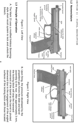
1.2 Nomenclature
Figure 1 Left View
1.3 Principle of Operation
A. The Mark 23 uses a modified linkless
Browning-style short recoil system to lock and unlock the
breech.
Figure 2 Right View
B. Upon firing, the pressure developed by the
propellent gas forces the slide and barrel
assembly to the rear. After approximately 3 mm,
the locking block will stop the rearward
movement of the barrel as the barrel is pivoted
downward due to the engagement of the angled
surfaces of the locking block with those located
rear sight
right
safety lever
extractor
barrel locking
block
front sight
ejection
port
accessory
mounting
groove
slide release
axle recess
trigger
magazine
release
lanyard loop
slide
recess for slide
release/stop
slide release
magazine
frame
accessory
mounting
groove
magazine
release
decocking
lever
left safety
lever
threaded insert
for accessory locking
flared
trigger guard
hammer
7
in the recoil spring guide rod. The locking block
will disengage from the slide and the slide will
continue rearward.
The extractor located in the slide will then
extract the fired cartridge case, the ejector
located in the frame on the left side of the
magazine well will eject the fired case as the
slide continues rearward and cocks the
hammer, and compresses the recoil spring.
The slide moves forward feeding the next
cartridge from the magazine into the chamber
and locking to the barrel breech.
C.
The slide locks open after the last round has
been fired and ejected.
WARNING
Do
not
rely
on
the
slide
lock
to
determine
if
the
magazine
is
empty.
Always
check
visually
and
physically
ensure
the
pistol
is
not
loaded.
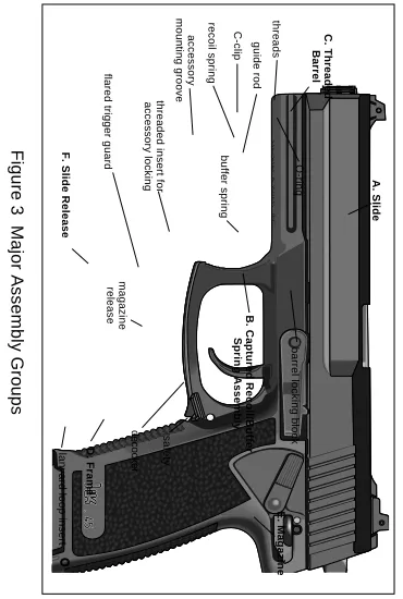
1.4 Major Assembly Groups
(See Figure 3)
A.
Slide
-
houses the firing pin, firing pin block and
extractor; cocks hammer during recoil.
B.
Captured Recoil/Buffer Spring Assembly
(with guide rod)
- absorbs recoil and returns
the slide and barrel to their forward positions;
reduces impact of slide on receiver during
recoil. The recoil spring is
“captured
” by a C-clip
on the end of the guide rod.
C.
Threaded Barrel
(with locking block)
-contains cartridge and propellent gases during
firing. The locking block initiates locking and
unlocking of the breech during movement of
slide. The O-ring holds the barrel tight in the
slide until unlocking.
D.
Frame
- serves as support to all major
components; controls functioning of pistol. The
slide release locks the slide with barrel and
recoil/buffer spring assembly to the metal
locking insert cast into the synthetic frame. A
lanyard loop is in the bottom of the grip for
attaching a lanyard. The trigger guard is flared
on both sides to preclude accidental actuation
8
E.
Magazine
- holds the cartridges in position for
feeding and chambering.
F.
Slide Release
- holds slide to rear when
engaged; releases slide when lever is
depressed.
Figure 3 Major Assembly Groups
A. Slide
C. Threaded
Barrel
D. Frame
E. Magazine
F. Slide Release
accessory
mounting groove
threaded insert for
accessory locking
O-ring
threads
barrel locking block
flared trigger guard
lanyard loop insert
C-clip
guide rod
recoil spring
buffer spring
B. Captured Recoil/Buffer
Spring Assembly
safety
magazine
release
9
1.5
Technical
Specifications:
Caliber
.45 ACP (Automatic Colt Pistol)
System of Operation
short recoil, semi-automatic
Locking System
Browning system (modified), linkless
Length
Barrel
5.87 in.
(149 mm)
Sight radius
7.76 in.
(197 mm)
Pistol
9.65 in.
(245 mm)
Weight
Magazine (empty) 12 or 10 rd. capacity
.24 lbs.
(.110 kg)
Magazine (w/12 rds M1911 Ball)
.81 lbs.
(.366 kg)
Magazine (w/10 rds M1911 Ball)
.72 lbs.
(.327 kg)
Pistol (w/ empty 12 or 10 rd magazine)
2.66 lbs.
(1.21 kg)
Pistol (w/ 12 rds M1911 Ball)
3.22 lbs.
(1.46 kg)
Pistol (w/ 10 rds M1911 Ball)
3.13 lbs.
(1.42 kg)
Trigger Pull
Single-action
4.85 lbs.
(2.20
kg)
Double-action
12.13 lbs.
(5.50
kg)
Height
5.90 in.
(150 mm)
Width
1.53 in.
(38.8
mm)
Muzzle velocity
M1911 230 grain ball
886 fps
(270 m/s)
+P 185 grain JHP
1142 fps
(348 m/s)
Maximum Effective Range
54.7 yds
(50 m)
Maximum Range (M1911 ball)
1,467 yds
(1,341 m)
Rifling
polygonal bore right hand twist
Magazine
staggered, 12 round capacity (10 round civilian)
Safety Features
1. safety lever (manual), 2. double-action mode with 12.1 lb. trigger
10
SECTION II - GENERAL DESCRIPTION
2.2 Description:
The Mark 23 is a semiautomatic,
magazine fed, recoil operated, double/single-action
pistol, chambered for the .45 ACP cartridge up to,
and including, the commercial +P cartridges.
WARNING
The
Mark
23
incorporates
single
and
double
action
modes
of
operation.
Anytime
the
trig-ger
is
pulled
with
the
safety
lever
in
the
fire
(down)
position
and
a
round
in
the
chamber,
the
pistol
will
fire
from
either
the
hammer
down
(DA)
or
cocked
position
(SA).
CHAPTER 2 OPERATING INSTRUCTIONS
SECTION I - SERVICE UPON RECEIPT OF MATERIAL
2.1
Initial Inspection
. Upon initial receipt, the pistol
is to be inspected to ensure it was received in
proper working order.
Step
Action
Reference
1
Remove pistol and items
from container
2
Remove packing material
3
Check for missing items
4
Field strip weapon and
inspect for:
para. 3.3
Missing parts
Proper assembly
5
Clean, dry and lubricate
(if necessary)
para. 3.7, 3.9
6
Assemble
para. 3.4
7
Safety/ function check
11 CAUTION A pair of Universal Mounting Grooves located on the front of the Mark 23 frame allow for a variety of accessories to be used with the pistol. Improperly designed or installed
accessories may result in damage to the
Mark 23 mounting grooves and/or the Mark
23. Such damage is not covered under
warranty. Be certain to use only HK Authorized
Accessories and follow installation and
precautions carefully. NOTE Accessories designed for the Universal Self-loading Pistol (USP) will not work on the Universal Mounting Grooves of the Mark 23.
2.3 Operation and Characteristics
A.
Double/Single Action
For double-action
(DA), pulling the trigger will cock the hammer
and immediately release it discharging a
chambered round. To fire the first chambered
round in single-action (SA), the hammer must
be manually cocked before pulling the trigger.
All shots after the first one will be fired
single-action because the slide automatically recocks
the hammer after each shot.
B.
Magazine
- The magazine is produced from
sheet steel and has a total capacity of 12
rounds. The rounds are positioned within the
magazine in a staggered arrangement. Rounds
are visible through the viewing holes located
along the back side of the magazine housing.
The viewing holes are marked with numerals
denoting the number of rounds remaining within.
The floor plate can be easily removed for
disassembly and cleaning of the magazine
components.
C.
Loaded Chamber Indicator
- The Mark 23
pistol does not have a loaded chamber
indicator. The extractor does not act as a
loaded chamber indicator.
D.
Decocking Lever
- The decocking lever allows
the operator to quietly lower the cocked hammer
without concern of an accidental discharge.
12
safely by moving the decocking lever fully into
the decocking (down) position. The decocking
lever cannot be depressed (and therefore does
not allow the hammer to be lowered) if the
safety lever is engaged. The decocking lever
always springs back into its disengaged (up)
position due to the spring pressure exerted by
the decocking spring.
E.
Safety Lever
- The safety lever is an
ambidextrous
“thumb
” lever located on the rear
of the frame. It is actuated by the firing thumb of
the operator. The safety lever blocks the
release of the cocked hammer when it is in the
engaged (up)
“safe
” position (See Figure 4a).
The safety lever is depressed downward into
the
“fire
” position (See Figure 4b). The safety
lever is not spring actuated and therefore must
be moved manually from one position to the
other by the operator.
Figure 4a
“Safe
” Position Figure 4b
“Fire
” Position
The safety lever cannot be placed in the
“safe
” (up)
position if the hammer is uncocked (down).
WARNING The pistol should always be carried with the
safety lever engaged when carried in the
single action mode. While there is a spring detent to prevent this, the safety lever can be moved to the “fire” position (down) with a minimum amount of force. This could happen during careless handling or during removal of the pistol from the holster. Always check
the position of the safety lever during
handling. left safety lever hammer white dot left safety lever
13
F.
Frame
- The front and back straps of the
fiberglass reinforced polymer frame are
checkered to ensure a firm grip, even with wet
hands or under conditions of rapid fire. The
trigger guard is extended, recurved and grooved
to provide a firm grip when using two hands or
gloves. The bottom of the trigger guard is flared
on both sides in front of the magazine release
lever to shield the lever from accidental
actuation.
A threaded insert is molded into the front face of
the trigger guard and the frame is grooved
forward of the trigger guard for attachment of an
accessory such as a laser aiming device or an
illuminator. The frame is a one-piece molded
component with metal inserts (locking insert and
guiding part) cast into the frame during
production. The slide rides on these metal
inserts during operation.
G.
Slide Release Lever
- This lever is used to lock
the slide open and for disassembling the
weapon. As a slide stop, it is depressed upward
by the magazine follower or the operator
’s
finger as the slide travels rearward during recoil
or manual operation. The slide release lever
engages the recess visible on the left side of the
slide and is spring actuated. The slide release
spring holds the slide release lever in a
disengaged (down) position until required. As a
disassembly lever, the slide release lever is
removed from the left side of the frame when
the slide is held rearward (see para. 3.3). The
slide release lever can be actuated by the firing
thumb of the right handed operator or the index
finger of the left handed operator.
H.
Magazine Release Lever
- This ambidextrous,
spring actuated lever holds the magazine within
the grip by engaging in the notch found in the
upper third of the magazine housing.
Depressing this lever with the firing hand index
finger or thumb will allow the magazine to drop
from the grip. The magazine release lever is
shielded from accidental actuation by the flared
trigger guard and the design of the synthetic
frame surrounding the lever.
2.4 Cycle of Operation
. Begins with weapon
14
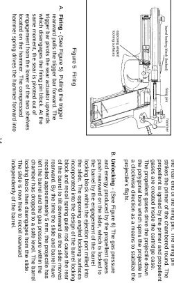
Figure 5 Firing
A.
Firing
- (See Figure 5) Pulling the trigger
rearward pulls the trigger bar forward. The
trigger bar pivots the sear actuator upwards
which disengages the firing pin block. At the
same moment, the sear is pivoted out of
engagement from the lower of the two shelves
located on the hammer. The compressed
hammer spring drives the hammer forward into
the rear end of the firing pin. The firing pin
strikes the primer of the chambered round. The
propellent is ignited by the primer and propellent
gases are created inside the cartridge case.
The propellent gases drive the projectile down
the polygonal bore which spins the projectile in
a clockwise direction as a means to stabilize the
projectile
’s flight.
B.
Unlocking
- (See Figure 6) The gas pressure
and energy produced by the propellent gases
push rearward on the slide, which is locked to
the barrel by the engagement of the barrel
locking block within the ejection port milled into
the slide. The opposing angled locking surfaces
incorporated into the design of the barrel locking
block and recoil spring guide rod cause the rear
of the barrel to tilt downward as the slide moves
rearward. By the time the slide and barrel have
recoiled approximately 5 mm, the projectile has
left the barrel and the gas pressure within the
chamber has dropped to a safe level. The barrel
locking block then disengages from the slide.
The slide is now free to recoil rearward
independently of the barrel.
barrel locking block (locked)
hammer
opposing angled
locking surfaces
firing pin
15
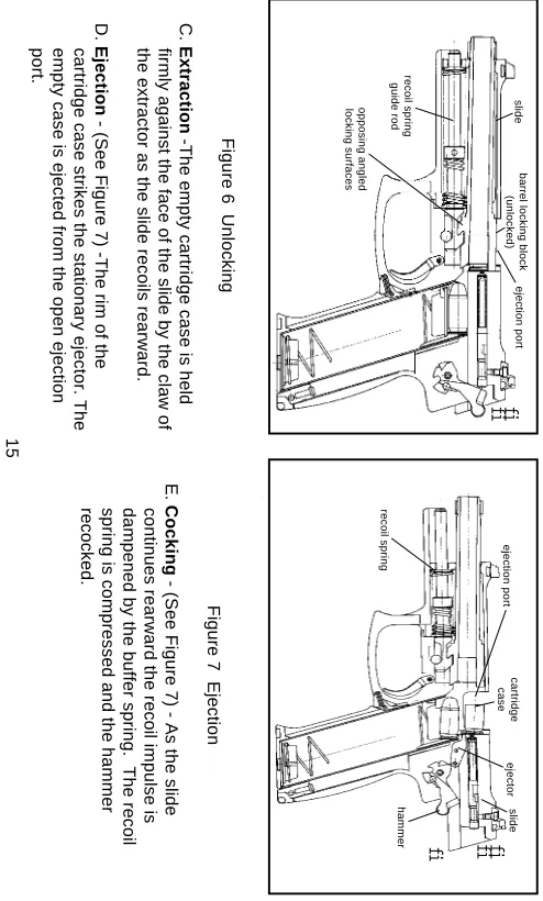
Figure 7 Ejection
E.
Cocking
- (See Figure 7) - As the slide
continues rearward the recoil impulse is
dampened by the buffer spring. The recoil
spring is compressed and the hammer
recocked.
Figure 6 Unlocking
C.
Extraction
-The empty cartridge case is held
firmly against the face of the slide by the claw of
the extractor as the slide recoils rearward.
D.
Ejection
- (See Figure 7) -The rim of the
cartridge case strikes the stationary ejector. The
empty case is ejected from the open ejection
port.
barrel locking block
(unlocked)
recoil spring
guide rod
opposing angled
locking surfaces
ejection port
fi
fi
slide
cartridge
case
recoil spring
ejection port
slide
hammer
ejector
16
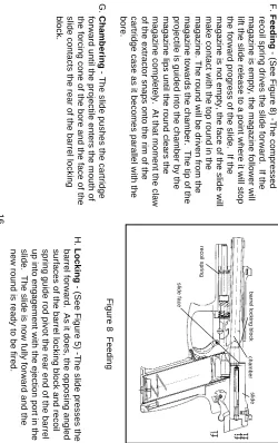
Figure 8 Feeding
H.
Locking
- (See Figure 5) -The slide presses the
barrel forward. As it does, the opposing angled
surfaces of the barrel locking block and recoil
spring guide rod pivot the rear end of the barrel
up into engagement with the ejection port in the
slide. The slide is now fully forward and the
new round is ready to be fired.
F.
Feeding
- (See Figure 8) -The compressed
recoil spring drives the slide forward. If the
magazine is empty, the magazine follower will
lift the slide release to a point where it will stop
the forward progress of the slide. If the
magazine is not empty, the face of the slide will
make contact with the top round in the
magazine. The round will be driven from the
magazine towards the chamber. The tip of the
projectile is guided into the chamber by the
magazine lips until the round clears the
magazine completely. At that moment the claw
of the extractor snaps onto the rim of the
cartridge case as it becomes parallel with the
bore.
G.
Chambering
- The slide pushes the cartridge
forward until the projectile enters the mouth of
the forcing cone of the bore and the face of the
slide contacts the rear of the barrel locking
block.
barrel locking block
slide face
slide
recoil spring
chamber
fi fi
17
2.5 Safety Features
A.
Safety Lever
- This safety blocks the release of the
cocked hammer in the SA mode. The safety lever
is an external, manually operated, ambidextrous
“thumb
” lever located on the left and the right side
of the frame further most back from the trigger. The
safety lever must be manually actuated by the
operator. The shaft of the safety lever moves the
sear block into a position where it blocks the
movement of the sear actuator. The sear actuator,
in turn, does not allow the sear to pivot forward and
thus the hammer cannot be released. Engaging the
safety lever also interrupts the function of the
decocking lever and blocks the hammer
mechanically. The safety lever does not restrict the
movement of the slide. The safety lever is held in
either the fire or safe position by a spring detent.
The safety lever cannot be placed in the safe (up)
position when the hammer is down (uncocked).
B.
Double-Action Mode
- This safety keeps the
hammer in an uncocked condition until the
moment of firing. The double-action mode
operates as a passive safety feature in the
pistol much as this mode of operation would in
any DA revolver or pistol. The hammer is left
uncocked until the decision to fire is made. At all
times the firing pin is locked by the firing pin
block until the trigger is pulled. Approximately
12.1 pounds of pressure on the trigger is
required to cock and release the hammer in the
DA mode of operation. The mode of operation
also permits subsequent hammer strikes on the
same chambered round by simply resqueezing
the trigger.
C.
Firing Pin Block
- This safety prevents the
firing pin from striking the primer when the
weapon is dropped, the hammer is bumped, or
when the slide slams forward. The firing pin
block is located in the slide and blocks the
forward movement of the firing pin. Only when
the trigger is depressed can the sear actuator
push the firing pin block upward against the
downward pressure exerted by the firing pin
block spring. Once the round has been fired and
the slide begins to recoil, the firing pin block is
pushed back down by the firing pin block spring
and engages within the recess provided in the
18
D.
Disconnector
- This safety prevents the release
of the hammer unless the slide is fully forward
and/or the trigger is reset (released) between
rounds. This important safety prevents serious
malfunctions from occurring, such as
“slam-fires
” (rounds that fire during loading), automatic
fire, or a round being fired out of the battery
(with the breech unlocked). The disconnector
disconnects the engagement of the trigger bar
and the sear actuator. The disconnector is
engaged (operating) after the slide has moved
2mm to the rear. The slide presses the leading
edge of the disconnector down and into
engagement with the trigger bar. When the
slide is fully forward, the leading edge of the
disengaged disconnector resides in a recess
provided in the bottom of the slide.
SECTION III - OPERATION UNDER NORMAL CONDITIONS
WARNING
Always
clear
the
pistol
before
handling
it.
2.6 Clearing Procedures
A. The Mark 23 pistol is not considered
“clear
” or
safe unless:
1. The magazine is removed,
2. The slide is locked to the rear, and
3. The chamber is free of brass or ammunition.
4. The safety lever is set on
“safe
”.
NEVER ASSUME THE PISTOL IS CLEAR!
B.
To Clear the Pistol:
1.
Make sure fingers are outside of the trigger
guard and the pistol is pointed in a safe
direction at all times!
2.
Decock Hammer or Engage Safety
- depress
decocking lever or engage the safety lever.
3.
Remove Magazine
- depress the magazine
release lever and remove the magazine from
19
4.
Open Slide
- lock slide open by pulling slide
rearward as you engage the slide release lever
(up). Watch for live round or empty case to be
ejected.
5.
Inspect Chamber
- inspect chamber for the
presence of a live round or empty case:
a. Visually view chamber through ejection
port.
b. Physically insert finger into chamber
through ejection port and check for
presence of cartridge case in chamber.
c. Remove any live rounds or empty cases
from the chamber or from within the
weapon.
The pistol is now considered
“clear
”.
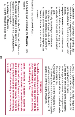
2.7 Loading and Unloading the Magazine
- (See
Figure 9)
The magazine of the Mark 23 pistol holds 10 rounds
of .45 caliber ammunition in the commercial
magazine and 12 rounds in the Law Enforcement/
Government magazine.
A.
Loading the Magazine
-1. Hold the magazine in one hand.
2. Hold a round between the index finger and
thumb of the other hand with the projectile
pointing towards the palm.
3. Press the rim of the round down against the
front edge of the follower or the top round in
the magazine and slide the round back under
the magazine lips.
4. Repeat steps 1 - 3 until the magazine is full.
The viewing holes in the back of the magazine
allow the operator to confirm the number of
rounds present within the magazine.
WARNING
Forcefully inserting a loaded magazine into
the Mark 23 may cause the pistol’s slide to
close, chambering a cartridge and making
the Mark 23 ready to fire.
When inserting a magazine, always be
certain that the pistol is pointed in a safe
direction with your fingers off the trigger
and outside the trigger guard. Failure to
do so could cause you to unintentionally
fire the pistol, resulting in serious injury
20
Figure 9 Loading the Magazine
B.
Unloading the Magazine
- exert pressure with
the finger on the base of the cartridge case and
push each round forward out of the magazine
one round at a time until the magazine is empty.
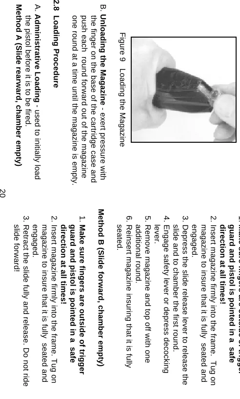
2.8 Loading Procedure
A.
Administrative Loading
- used to initially load
the pistol before it is to be fired.
Method A (Slide rearward, chamber empty)
1.
Make sure fingers are outside of trigger
guard and pistol is pointed in a safe
direction at all times!
2. Insert magazine firmly into the frame. Tug on
magazine to insure that it is fully seated and
engaged.
3. Depress the slide release lever to release the
slide and to chamber the first round.
4. Engage safety lever or depress decocking
lever.
5. Remove magazine and top off with one
additional round.
6. Reinsert magazine insuring that it is fully
seated.
Method B (Slide forward, chamber empty)
1.
Make sure fingers are outside of trigger
guard and pistol is pointed in a safe
direction at all times!
2. Insert magazine firmly into the frame. Tug on
magazine to insure that it is fully seated and
engaged.
3. Retract the slide fully and release. Do not ride
21
4. Engage safety lever or depress decocking
lever.
5. Remove magazine and top off with one
additional round.
6. Reinsert magazine insuring that it is fully
seated.
B.
Tactical Reloading
- used to quickly reload
pistol once firing has begun.
Method A (Slide rearward, chamber empty)
1.
Make sure fingers are outside of trigger
guard and pistol is pointed in a safe
direction at all times!
2. Keep eyes on target area.
3. Depress the magazine release with finger or
thumb of firing hand to drop magazine.
4. At the same time, retrieve a full magazine with
the non-firing hand and insert firmly into the
frame. Tug on magazine to insure that it is
fully seated and engaged.
5. Depress slide release to chamber first round.
6. Continue firing.
Method B (Slide forward, rounds remaining
in magazine and chamber)
1.
Make sure fingers are outside of trigger
guard and pistol is pointed in a safe
direction at all times!
2. Keep eyes on target area.
3. Depress the magazine release with finger or
thumb of firing hand to drop partially empty
magazine.
4. At the same time, retrieve full magazine with
non-firing hand and insert firmly into the frame.
Tug on the magazine to insure that it is fully
seated and engaged.
5. Weapon is now back at full capacity without
rendering chamber empty and weapon
useless.
6. Continue firing
2.9 Readying the Pistol for Firing
Disengage the safety lever (if engaged). Red hazard
22
WARNING
1.
BE SURE OF YOUR TARGET AND WHAT
’ S BEHIND IT! Even a .45 caliber projectile can easily penetrate wood, plasterboard walls, or a car door, and can travel as far as one mile! 2. Ensure that all parts of your hand and body are kept away from the muzzle of the pistol at all times! 3. Always wear eye and ear protection where possible when firing the pistol. 4. Whenever the pistol is dropped on a hard
surface landing on the hammer (cocked or
down), it should be sent to the HK Service Department as soon as practicable to inspect the sear axle. If the sear axle is bent, it should be replaced.
2.10 Firing the Pistol
A.
Single-action mode
(Hammer back/cocked)
Affords operator the best and lightest trigger pull
(
≈
4.8 lbs.) for precise and accurate bullet
placement.
With manual safety disengaged:
1. Aim at the target.
2. Fire the weapon by pressing the trigger straight
to the rear with gradually increasing pressure.
3. Engage the safety lever to remain in the
single-action mode once firing is completed.
CAUTION Single action mode trigger pull is lighter & shorter than double action mode. Keep your finger off the trigger & outside the trigger guard except when firing the Mark 23. B. Double-action mode (Hammer down/uncocked)
Provides the operator with a long, heavy (
≈
12.1
lbs.) trigger pull for the first shot only. Subsequent
shots will be fired in single-action mode as the
slide will automatically cock the hammer after
each round is fired. The double-action mode of
fire is often the preferred mode of fire when
safety during handling and carrying is of greater
concern than first round accuracy.
1. Aim at the target.
2. Fire the weapon by pressing the trigger straight
to the rear with gradually increasing pressure.
3. Depress the decocking lever to lower the
hammer to return to the double-action mode
once firing is complete, or engage the safety
23
SECTION IV - OPERATION UNDER UNUSUAL CONDITIONS
NOTE
Unusual
conditions
are
defined
as
any
climatic
condition
requiring
special
maintenance
of
the
pistol.
Perform
the
maintenance
outlined
for
the
climate
that
most
applies
to
your
operational
area.
Refer
to
paragraph
3.9
for
lubrication
instructions.
CAUTION
If
extensive
corrosion
is
found
and
cleaning
does
not
solve
the
problem,
contact
the
HK
Service
Department.
2.11 Extreme Cold
A. When operating pistol in extremely cold
climates, clean and lubricate the pistol inside at
room temperature if possible.
B. Apply a light coat of LAW (Lubricant, Arctic
Weapons) to all functional parts.
C. To prevent freezing, keep the pistol covered
when moving from a warm to a cold area. This
will allow gradual cooling.
D. Always keep the pistol dry.
E. Do not lay a hot pistol in snow or ice.
F. Keep ammunition dry; moisture will cause
malfunctions. Do not lubricate the
ammunition.
G. Always keep snow out of the bore of the barrel.
If snow should get into the bore, clean the bore
before firing using a swab and cleaning rod.
2.12 Hot, Wet Climates
A. Perform maintenance more frequently. Inspect
hidden surfaces for corrosion. If corrosion is
found, clean and lubricate.
B. To help prevent corrosion, remove hand prints
with a cloth. Dry and lubricate the pistol with
CLP/LSA (Cleaner, Lubricant, Protectant).
C. Check ammunition and magazines frequently for
corrosion. Clean the magazine using CLP/LSA
and wipe dry with a cloth. If necessary, clean
ammunition with a dry cloth.
D. Always keep mud out of the barrel. If mud
should get into the bore, clean it before firing
24
2.13 Hot, Dry Climates
A. Dust and sand will get into pistol and cause
malfunctions and excessive wear on component
contact surfaces during firing. Keep the pistol
covered when possible.
B. Corrosion is less likely to form on metal parts in
a dry climate. Therefore, lightly lubricate
internal working surfaces only with CLP/LSA.
Do not lubricate external parts of the pistol.
Wipe any excess lubricant from exposed
surfaces. Do not lubricate internal components
of magazine.
2.14 Heavy Rain and Water Operations - All
Climates
A. Perform maintenance in accordance with the
appropriate climatic conditions.
B. Always attempt to keep pistol dry.
C. Always try to drain any water from barrel prior to
firing. Dry the bore with a swab and cleaning
rod.
D. Lightly lube the bore and chamber. Generously
lube internal and external surfaces of the pistol
with CLP/LSA.
E. In extreme or prolonged wet or saltwater
conditions, cover serial number and proof mark
on barrel and slide with a temporary protective
coating. These are etched on through the
permanent protective coating on the barrel and
slide and therefore may corrode under these
25
SECTION V - MALFUNCTIONS AND STOPPAGES
2.15 Remedial Action
- Remedial Action is the
action performed to remedy an unanticipated
interruption of the pistol
’s operation and place the
pistol back into operation.
WARNING During remedial action, make certain the pis-tol is pointed in a safe direction at all times. A.
Clear the pistol!
B. Attempt to lock slide.
C. Remove magazine.
D. Inspect chamber.
E. Insert fresh magazine
F. Release slide.
G
. Attempt to fire the pistol.
If the Mark 23 fails to fire, return the weapon to the
HK Service Department for service.
WARNING If a round is assembled without powder (a fault of the manufacturing process), the primer
alone has enough power to propel the
projectile into the bore. A projectile lodged in the bore may cause damage to the barrel and/ or the pistol if another round is fired and could cause personal injury. This event is
commonly called a
“
pop and no kick
” or “ squib load ” and is characterized by a much reduced report and little or no movement of the slide. An alert operator should notice the occurrence of this event in time to avoid firing the next round.
Selection and Use of a Holster
Selection
When selecting a carrying holster for the
HK Mark 23, it is important to consider the following
points:
1
. The holster must not make contact with or actuate
any of the operating controls. This includes the
hammer, slide release, magazine release lever,
26
trigger. The design of the holster must also not
actuate these controls when the pistol is carried in,
drawn from, or returned to the holster
.
2. The holster should not cause the slide to move
(unlock) when the pistol is returned to the holster.
3. Accommodations must be provided in the holster
for any accessories that might be present on the
pistol.
4. Choose a holster designed for the Mark 23.
Returning the Pistol to the Holster
- The HK
Mark 23 must be made
“safe
” (or cleared) prior to
returning it to the holster. The pistol is considered safe
to return it to the holster when:
1. All fingers are off of the trigger and out of the trigger
guard and;
2. The pistol is
“clear
” or;
3. The hammer is in the decocked (down) position or;
4. The safety lever is engaged in the safe position
when the hammer is cocked.
WARNING
The pistol must never be returned to the
holster
unless
the
above
procedures
have
been
followed
or
injury
or
death
could
27
CHAPTER 3 MAINTENANCE INSTRUCTIONS
SECTION I - TOOLS & EQUIPMENT
NOTE
The
service
life
and
performance
of
your
HK
Mark 23 is dependent upon the correct
handling
and
proper
care
by
the
operator.
3.1 Operator Tools and Equipment Required.
At
a minimum, you will require the following materials
to maintain the Mark 23 pistol and its components:
• Cleaning rod with handle and eyelet
• Long handled nylon brush
• Bronze bristle bore brush (.45 caliber)
• Cotton swabs
• Solvent/bore cleaner/CLP
• Cleaning patches (.45 caliber)
• Rag
CAUTION
Use
safety
goggles
when
using
solvents
and
exercise
care
if
using
compressed
air.
SECTION II - PREVENTATIVE MAINTENANCE (PM)
SERVICE CHECKS & MAINTENANCE PROCEDURES
3.2 General
- This PM Service section lists those
required checks and services to be performed by
personnel who operate the Mark 23 pistol. This
section includes the services required to prepare the
pistol for operation, to check the pistol during
operation, and to ensure proper function after
maintenance. Before performing any PM Service
procedures, ensure that the Firearm Service Record
has been updated with the correct round count and
any PM Service procedures documented. If your
equipment fails to operate, refer to the
Trouble-shooting Table in Section III.
WARNING
Before starting an inspection procedure
CLEAR
THE
PISTOL!
Inspect
the
chamber
to
ensure that it is empty. Do not keep live
ammunition
near
maintenance
/work
28
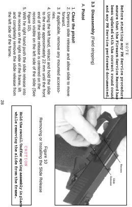
Figure 10
Removing or Installing the Slide Release
CAUTION
H
old
the
recoil/buffer
spring
assembly
in
place
while
removing
the
slide
from
the
frame.
NOTE
Before
starting
any
PM
Service
procedure
ensure
that
the
Firearm
Service
Record
has
been
updated
with
the
correct
round
count
and
any
PM
Service
performed
documented.
3.3 Disassembly
(Field stripping)
A.
Pistol
1.
Clear the pistol!
2. Depress slide release and allow slide to move
forward.
3. If applicable, remove any mounted
accesso-ries.
4. Using the left hand, retract and hold the slide
to the rear approximately 22 mm until the front
end of the slide release is centered on the
recess visible on the left side of the slide (See
Figure 10).
5. With he right hand push the slide release into
the recess on the right side of the frame, lift
and completely remove the slide release from
the left side of the frame.
Recess
Slide
29
10-Round Civilian Magazine
1. Using a blunt pointed instrument depress the
locking insert detente located in the floor plate
and hold it there
.
2. Place a portion of either hand over the base of
the magazine to control the release of the
magazine spring and locking insert.
3. With the locking detente still depressed,
squeeze the floor plate locking tabs located on
the right and left sides of the magazine.
4.
Gradually
allow the locking insert and magazine
spring to expand out of the magazine housing.
5. Remove the locking insert, magazine spring and
magazine follower from the magazine housing.
CAUTION
Beware
of
the
spring
tension
exerted
by
the
magazine spring while removing and
installing
the
magazine
floor
plate.
Keep
the
base of the magazine pointed in a safe
direction
(away
from
face
and
eyes)
during
disassembly
and
assembly.
6. Remove the slide with barrel and captured
recoil/buffer spring assembly off of the frame by
sliding it forward.
7. Remove the captured recoil/buffer spring
assembly from the barrel and slide by lifting up
on the rear of the guide rod. The entire
assembly can now be lifted out of the slide.
8. Lift the rear of the barrel by the locking block
and withdraw it from the slide.
B.
Magazine
12-Round Law Enforcement Magazine
1. Using a blunt pointed instrument depress the
locking detent protruding through the bottom of
the magazine floor plate and
hold it there.
2. Place a portion of either hand over the base of
the magazine to control the release of the
magazine spring and locking plate.
3.
Slowly
slide the floor plate forward off of the
magazine housing.
4. Gradually allow the locking plate and magazine
spring to expand out of the magazine housing.
5. Remove the locking plate, magazine spring and
30
CAUTION
Operator
disassembly
of
the
Mark
23
pistol
is
now complete. Only trained HK Service
Department
personnel
may
disassemble
the
weapon
further.
3.4 Reassembly
(From field strip)
A.
Magazine
12-Round Law Enforcement Magazine
1. Place the magazine follower onto the end of the
magazine spring having the loop at the end of
the wire on the left side of the follower.
2. Insert the follower and the magazine spring into
the magazine housing.
3. Place the locking plate onto the protruding end
of the magazine spring so that the locking
detent is visible (see Figure 11A).
4. Push the locking plate down into the magazine
housing against the pressure of the magazine
spring and
hold it there
.
5. Slide the floor plate over the base of the
magazine housing and locking plate from front
to rear making sure that:
a. The floor plate engages the tabs located on
the left and right sides of the magazine
housing.
b. The floor plate is fully seated on the magazine
housing.
c. The locking detent fits within the hole provided
in the floor plate.
d. Check the magazine for proper assembly by
insuring that the follower slides up and down
freely within the magazine housing and with
spring tension. Also check that the magazine
follower rises within the housing to be nearly
flush against the bottom of the magazine lips.
Figure 11A Assembly of Magazine Follower & Spring
(12-Round Law Enforcement Magazine)
magazine housing
floor plate
magazine
follower
locking plate
31
Figure 11B 10-Round Civilian Magazine
(Disassembled)
10-Round Civilian Magazine
(see Figure 11B)
1. Place the magazine follower onto the
magazine spring with the end of the spring
positioned on the left of the follower.
2. Insert the follower and magazine spring into
the magazine housing.
3. Place the locking insert (on 10-round
magazines) onto the protruding end of the
magazine spring so that the rounded
corners
face towards the front of the magazine.
4. Push the locking plate down into the magazine
housing against the pressure of the magazine
spring
and hold it there.
5. Push the floor plate up onto the base of the
magazine housing until the locking tabs
engage in the sides of the housing. Check to
see if the locking tabs on the floor plate are
securely locked into the housing and the
locking detente on the locking plate fits within
the hole in the floor plate.
6. Check the magazine for proper assembly by
insuring that the follower slides up and down
freely within the magazine housing and with
spring tension. Also check that the magazine
follower rises within the magazine housing to
be nearly flush against the bottom of the
magazine lips.
B.
Pistol
1. Insert the muzzle of the barrel through the
large hole located in the front of the slide.
2. Drop the barrel down into the slide and push it
forward until the O-ring engages the slide, the
locking block fits within the ejection port, and
the angled locking surface of the locking block
are visible along the bottom of the slide. The
magazine housing
floor plate
magazine
follower
locking insert
32
O-ring will now hold the muzzle tight in the
front of the slide.
3. Install the captured recoil/buffer spring
assembly into the slide so that the front of the
recoil spring guide rod engages in the smaller
hole located in the front of the slide.
4. Align the opposing angled locking surfaces of
the recoil spring guide rod with those located
on the bottom of the barrel locking block.
5. Push the rear of the recoil/buffer spring
assembly forward enough so that the recoil
spring retainer can be engaged on the shelf
provided on the front of the barrel locking
block (see Figure 12).
6. Hold the slide in the right hand with the thumb
holding the rear end of the recoil/buffer spring
assembly in place on the slide (see Figure 13).
7. Hold the frame in the left hand. Position the
rear of the slide above the front edge of the
frame.
8. Draw the slide back onto the frame so that the
rails of the locking insert and guiding part slide
within the grooves in the slide.
9. Retract the slide to the point where the recess
in the left side of the slide is centered on the
hole where the axle of the slide release will go.
10. Hold the slide in this position and insert the
slide release from the left to right into the
frame until it is flush with the side of the frame
and locks in place.
Figure 12 Proper Position for the Captured Recoil/
Buffer Spring Assembly on the Barrel Locking Block
locking block
barrel
threads
O-ring
shelf
buffer spring
recoil spring
guide rod
recoil spring
C-clip
recoil spring
33
Figure 13 Correct Position for Holding Slide
for Reassembly
NOTE
Operator
reassembly
of
the
Mark
23
pistol
is
now complete, but not finished without a
safety/function
check.
3.5 Safety/Function Check
A. A safety/function check should be performed
anytime the pistol is reassembled. This quick
check indicates whether or not the pistol was
properly assembled and with all the
compo-nents. A properly executed safety/function
check can also reveal many of the more obvious
malfunctions that could occur between the
interactive components of the pistol.
B.
Always
clear the pistol before performing a
safety/function check!
Don’t assume the
pistol is clear!
1.
Clear the pistol!
2. Actuate the slide and the operating controls to
insure that:
a.
Magazine and catch
- the magazine is
held securely in place by the magazine
catch and that it drops free of the frame
when the catch is depressed.
b.
Slide
- the slide moves freely and without
binding on the frame (with and without a
magazine installed).
c.
Barrel
- the barrel locking block does lock
fully into battery within the ejection port of
the slide as the slide is closed.
d.
Slide Release
-1) The slide release does hold the slide
open when retracted while:
frame
slide
thumb holding recoil/buffer spring
34
a) an empty magazine is in place.
b) the slide release is engaged (pressed
upwards).
2) The slide release does permit the slide to
snap forward when:
a) the slide release is depressed.
b) the slide is retracted without a
magazine installed.
3) The slide release does rebound with
spring pressure.
3. Perform the following safety checks:
a. Safety Lever Test
.
1) With the pistol unloaded and hammer
down (uncocked) attempt to press the
safety lever upward into the safe position.
The safety lever should not engage. If the
safety lever engages, return the pistol to
the HK Service Department for service.
2) With the pistol unloaded, the hammer
cocked, move the safety lever several
times from the
“safe
” to
“fire
” position. If
the safety lever does not have a
pro-nounced stop when moved from
“safe
” to
“fire
” position and back, return the pistol
to the HK Service Department for service.
3) With the pistol unloaded, cock the
hammer and press the safety lever
upward into the safe position. Grasp the
pistol in the shooting position and
squeeze the trigger three or four times. If
the hammer falls, return the pistol to the
HK Service Department for service.
b. Decocking Lever Test
.
1
) With the pistol unloaded, cock the hammer
and depress the decocking lever. If the
hammer does not fall or the decocking lever
does not rebound (upward into its normal
position) with spring pressure, return the
pistol to the HK Service Department for
service.
2) With the pistol unloaded, cock the
hammer and press the safety lever
upward into the safe position. Attempt to
35
times. If the hammer falls, return the
pistol to the HK Service Department for
service.
c. Decocked (hammer down) Test
.
NOTE
On
the
Mark
23
pistol
when
decocked
(hammer
down),
the
sear
is
engaged
with
the
hammer
at
a
rebounded
stop
position
not
touching
the
rear
of
the
firing
pin.
1)
With the pistol unloaded, squeeze the
trigger allowing the hammer to cycle in the
double action mode. After the hammer
drops, retain pressure on the trigger. With
the non-firing hand apply pressure with your
finger tips on the rear of the hammer. The
hammer should move forward toward the
firing pin. Release pressure on the trigger
while still retaining pressure with fingers on
hammer. Release pressure on hammer. If
the hammer fails to spring back into the stop
position, return the pistol to the HK Service
Department for service.
2) With the pistol unloaded, hammer
uncocked, trigger forward, apply pressure
to the hammer with your finger tips. If the
hammer moves forward to the firing pin,
return the pistol to the HK Service
Department for service.
d. Disconnector and Trigger Test
.
1) With the pistol unloaded, cock the
hammer, push the slide rearward
approximately 3/16 inches (2mm) and
hold in that position while squeezing the
trigger. If the hammer falls, return the
pistol to the HK Service Department for
service.
2) With the pistol unloaded, pull the slide
rearward until the slide stop will engage.
Squeeze the trigger and release the slide
forward simultaneously. If the hammer
falls, return the pistol to the HK Service
36
3) With the pistol unloaded, pull the slide
rearward and engage the slide. Squeeze
the trigger and release the slide forward
simultaneously. Release pressure on the
trigger. If the trigger does not return to its
normal position, return the pistol to the
HK Service Department for service.
Squeeze the trigger and the hammer
should fall. If the hammer does not fall,
return the pistol to the HK Service
Department for service.
4) With the pistol unloaded and the trigger
forward, apply thumb pressure to the
cocked hammer. If the hammer lowers
solely as a result of thumb pressure,
return the pistol to the HK Service
Department for service.
3.6 Function Firing
If any corrective action was accomplished, the pistol
shall be function fired a full magazine prior to being
cleaned and returned to service use.
3.7 Cleaning - performed after each firing, or
every twelve (12) months, or after any exposure
to extreme environmental conditions such as
salt, fog, sand, dust, mud, water, etc.
A.
Normal Cleaning
-1.
Clear the pistol!
2. Disassemble the pistol into the major
assem-bly groups.
a.
Slide
-1) Scrub all internal surfaces of the slide
using the nylon brush moistened with
solvent.
2) Remove all loose fouling from all surfaces
of the slide using a rag and cotton swabs.
b.
Recoil/buffer spring assembly
- remove
all visible fouling using solvent, a nylon
brush, a rag, and cotton swabs.
c.
Barrel with locking block
-1) Moisten the bronze bore brush with
solvent and scrub the bore from chamber
to muzzle at least six passes, back and
forth. (Note: Repeat steps 1 and 2 until a
cleaning patch can be pushed through the
37
NOTE
All parts of the HK Mark 23 can be immersed in
any cleaning solvent that it is safe to put your
hands into. Gasoline and other motor fuels are
not authorized cleaning solvents. Avoid
clean-ing the frame in an ultrasonic cleaner as this can
remove the colored “safe” and “fire” dots.
3.8 Inspection
During and after cleaning the operator should
inspect the pistol and its components for any
irregularities that may cause problems during its
operation. If any potential deficiencies are noted,
they should be corrected immediately and/or
brought to the attention of the HK Service
Depart-ment for service.
A.
Visually Inspect the Pistol
and Magazine for:
1. Damaged or missing parts
2. Improper assembly or function
3. Absence of free movement, where applicable
4. Absence of spring tension, where applicable
2) Remove the loose fouling using cleaning
patches.
3) Scrub outside surfaces of barrel and
locking block with the nylon brush
moistened with solvent.
4)
Scrub the threads of the barrel and O-ring
with the nylon brush moistened with
solvent.
5) Remove all loose fouling using a rag and
cotton swabs.
d.
Frame
-1) Scrub all internal surfaces where carbon
fouling is visible using the nylon brush
moistened with solvent. Concentrate on
the area normally covered by the slide.
2)
Using the rag and cotton swabs, remove all
loose fouling from all areas of the frame.
e.
Magazine
-1) The magazine is disassembled for
cleaning.
2) Scrub the top of the magazine,
concen-trating on the follower and feed lips, using
the nylon brush moistened with solvent.
3) Using the rag and cotton swabs, remove
all loose fouling from all surfaces of the
38
5. Unaccustomed looseness
6. Parts exhibiting signs of cracks, burrs, dents,
or obvious signs of damage or stress
7. Presence of stops or tactile clicks in controls,
where applicable
8. General overall cleanliness
9. Presence of proper lubrication
10. Presence of corrosion or degradation of
surface finish
11. Rubber hammer spur for cracks or chips
CAUTION
If
the
rubber
hammer
spur
is
badly
cracked
or
chipped,
drop
safety
could
be
degraded.
Pistol
should
be
returned
to
HK
Service
Department
to
replace
hammer.
3.9 Lubrication
All metal surfaces of the Mark 23 pistol have a
special surface treatment that resists all types of
corrosion including corrosion resulting from
exposure to salt water. However, this surface
treatment does not reduce friction between parts,
therefore, lubricant must be applied to the pistol.
Any type of high-quality, medium weight lubricant
(oil or grease) specifically designed for use on
firearms, such as
“Break-Free
” (C.L.P.), will work
well on the Mark 23 pistol.
Do not use lubricants that boast of their ability to
penetrate metal as these substances may deaden
primers.
A. Where
and how much?
No Lube -
(surface is dry and not slippery to the
touch)
• Plastic components
Light Lube
(finger run across surface yields
little or no lube)
• Bore, chamber, and exterior of barrel
• All metal parts
• All internal parts in slide and frame
• Magazine housing and spring
• Recoil/buffer spring assembly
• Sights
39
Medium Lube
(finger run across surface
yields some lube but lube does not run down
surface when held in a vertical position)
• Barrel locking block
• Slide rails
• All operating controls
• Locking insert and guiding part
• Extractor
Heavy Lube
(Lube runs down surface when
held in a vertical position)
NOTE
No heavy lube is required on the Mark 23
pistol.
Reapply lubrication periodically during firing as it
burns off from the heat. Apply lubricant using a
shaving brush, cotton swabs, patches, or rag. A
spray bottle also works well using compressed air to
circulate the lubricant into all parts and to remove