Nam-Su Jho, Jung Hee Cheon, Myung-Hwan Kim, and Eun Sun Yoo
ISaC and Department of Mathematical Sciences, Seoul National University, Seoul 151-747, Korea
{drake, jhcheon, mhkim, eunsun}@math.snu.ac.kr
Abstract. We propose a new broadcast encryption scheme πbased on the idea of ‘one key per each punctured interval’. LetNandrbe the numbers of total users and revoked users, respectively. In our scheme withp-puncturedc-intervals, the transmis-sion overhead is asymptotically p+1r as r grows. We also introduce two variants of our scheme to improve the efficiency for smallr. Our scheme is very flexible with two parameterspandc. We may takepas large as possible if a user device allows a large key storage, and setcas small as possible if the storage size and the computing power is limited. Our scheme also possesses another remarkable feature that any number of new users can join at any time without key refreshment, which is not possible in other known practical schemes.
1 Introduction
Broadcast encryption(BE) is a cryptographic method for a center to efficiently broadcast digital contents to a large set of users so that only non-revoked users can decrypt the contents. BE has a wide range of applications such as internet or mobile broadcast of movies, news or games, pay TV, and even CD or DVD, to name a few.
In broadcast encryption, the center distributes to each useruthe setKu of keys,
called the user key set of u, in the system setup stage. We assume that the user keys are not updated afterwards, that is, user keys arestateless. Asessionis a time interval during which only one encrypted message (digital contents) is broadcasted. The session key, say SK, is the key used to encrypt the contents of the session. In order to broadcast a message M, the center encrypts M using the session key
SK and broadcasts the encrypted message together with a header, which contains encryptions of SK and the information for non-revoked users to recover SK. In other words, the center broadcasts
hheader ;ESK(M)i,
where ESK(M) is a symmetric encryption of M by SK. Then, every non-revoked
user ucomputes F(Ku,header) =SK and decryptsESK(M) withSK, where F is
a predefined algorithm. But for any revoked userv,F(Kv,header) should not render
SK. Furthermore, there should be no polynomial time algorithm that outputsSK
even with all the revoked user keys and the header as input.
The length of the header, the computing time of F and the size of a user key are called the transmission overhead, the computation cost and the storage size, respectively. The main issue of broadcast encryption is to minimize the transmission overhead with practical computation cost and storage size.
The notion of broadcast encryption was first introduced by Berkovits[2] in 1991 using polynomial interpolation and vector based secret sharing. Fiat and Naor[7] in 1993 suggested a formal definition of broadcast encryption and proposed a sys-tematic method of broadcast encryption. The polynomial interpolation method was improved by Naor and Pinkas[14] in 2000 to allow multiple usage. The first prac-tical broadcast encryption scheme was proposed in 2001 by Naor et al.[13], called theSubset Difference(SD) method. This was improved by Halevi and Shamir[11] in 2002 by adopting the notion of layers and thereby the improved scheme is called the Layered Subset Difference(LSD) method. Both SD and LSD are based on tree structure and they are the best known broadcast schemes up to now. To be more precise, let N be the total number of users and r be the number of revoked users. The SD scheme requires 2r transmission overhead and O(log2N) storage size for each user. The computation cost is onlyO(logN) computations of one-way permu-tations. The LSD scheme reduces the storage size toO(log3/2N) while keeping the computation cost same. But the transmission overhead increases to 4r in LSD. For other interesting recent articles on broadcast encryption, we refer the readers [8], [3].
In this paper, we propose a new broadcast encryption scheme based on the idea of “one key per each punctured interval”. It has been a general belief that at least one key per each revoked user should be included in the overhead and hence r seems to be the lower bound of the transmission overhead in any broadcast encryption scheme with reasonable computation cost and storage size. In our scheme withp-punctured
c-intervals, however, the transmission overhead is about p+1r +N−c r which breaks the barrier of r, for the first time under our knowledge if r is not too small, even whenp= 1, wherecis a predetermined constant andris not too small. Although we setc= 100 or 1000 for comparison purpose here, we can choose anycthat is suitable for other purposes. The computation cost is very cheap with onlyc−1 computations of one-way permutations. The storage size is O(cp+1), which is practical for most user devices if p is small. Our scheme is very flexible with two parameters p and
c. If a user device allows a large key storage like set-top boxes and DVD players, we may take p as large as possible to reduce the transmission overhead, which is much more expensive. If a user device has limited storage and computing power like smart cards and sensers, then we may setcas small as possible. Another remarkable feature of our scheme is that it does not have to preset the total number of users -any number of additional users can join at -any time, which is not possible in tree based schemes.
Our idea is to put all the users on a straight line and divide the line into subin-tervals of length at mostc beginning and ending with non-revoked users containing
p or less revoked users in between. Then, to each of such intervals, the center as-signs just one key, which can be derived by all non-revoked users in the interval, for decrypting the session key.
This paper is organized as follows : In Section 2, we propose our scheme with
p-punctured intervals together with efficiency and security analysis. In Section 3, we introduce layers to our scheme. We also suggest a scheme using tree structure of punctured circles. In Section 4, we compare our schemes with SD and LSD and discuss some practical issues. We give concluding remarks in Section 5. Detailed proofs of lemmas and theorems are provided in Appendix.
2 The Punctured Interval Scheme π
2.1 Framework
Let L be a straight line with N dots (users) on it, where N is the number of total users. In our scheme, each user is indexed by an integer k ∈ [1, N] and he/she is represented by thek-th dot, denoted byuk, in the lineL. ConsiderLas the set ofN
users and define S(cond) to be the set of all subsets ofL satisfying a given condition
cond. Assign each subset in S(cond) one key, called a subset keythat can be derived by each user in the subset using his/her user keys. For each session, the center finds as minimal as possible disjoint subsetsS1, S2, . . . , Sm inS(cond), whose union covers all non-revoked users, withmas small as possible. And then the center encrypts the session keySKwith the subset keys of thoseSµ’s, respectively. Thesemencryptions
ofSKtogether with information onSµ’s form the header. This numbermis usually
defined to be the transmission overhead.
Encryption In each session, the center finds disjoint subsets S1, S2, . . . , Sm in
S(cond), whose union covers all non-revoked users, and their corresponding subset keysK1, K2, . . . , Km. The center then encrypts the session key SK and a message
M withKµ’s andSK, respectively, and broadcasts
hinfo1,info2, . . . ,infom;EK1(SK), EK2(SK), . . . , EKm(SK) ; ESK(M)i,
where infoµis the information of on the subsetSµand E is a symmetric encryption
algorithm like AES for example.
Decryption Receiving the encrypted message
hinfo1,info2, . . . ,infom;C1, C2, . . . , Cm;M0i,
each non-revoked userufirst finds the subsetSµ that he/she belongs and the
corre-sponding subset keyKµ. With this,ucomputesDKµ(Cµ) =SKandDSK(M0) =M
in order.
2.2 Punctured Intervals
Let p≥0 and c >0 be integers. By a p-punctured c-interval we mean a subset of c or less consecutive users starting from and ending at non-revoked users and containingpor less revoked users. LetS(p;c)be the set of allp-puncturedc-intervals. In each session, the p-punctured c-intervals are to be determined under the fol-lowing rule :
• The first p-punctured c-interval starts from the leftmost non-revoked user, and each of the following starts from the first revoked user after the last non-revoked user of the previous.
• Each p-punctured c-interval contains the maximal possible number of users. Fig.1 illustrates how to make p-punctured c-intervals with an example when
p= 1, c= 6 :
e e e e e e e e e e e e e e e e e e e e¡@ ¡@ ¡@ ¡@ ¡@
µ ´ µ ´ µ ´ ª
Fig. 1.1-punctured 6-intervals
The p-punctured c-interval starting fromui and ending at uj with ux1, . . . , uxq
revoked users is denoted byPi,j;x1,...,xq orPi,j;X in short forX={x1, . . . , xq}, where
1≤j−i+ 1≤c, 0≤q ≤p, and i < x1 <· · ·< xq < j if there are revoked users.
2.3 Punctured Interval Scheme (p;c)-π
In this subsection, we propose the punctured interval broadcast encryption scheme (p;c)-π(PI - Punctured Interval). We assign just one key to each p-punctured c -interval, which can be easily derived by all non-revoked users in that -interval, and construct key chains using one-way permutations in order to reduce the storage size.
Key Generation Let ht : {0,1}` → {0,1}` be one-way permutations for t =
0,1, . . . , p, where `is the key length. To assign one key to each p-punctured inter-val, we randomly choose N keys K1,1, K2,2, . . ., KN,N to be given to u1, . . . , uN,
respectively. From eachKi,i the center constructs the one-way key chains under the
following rule : For any possible p-punctured c-intervalP starting from ui given,
• The one-way key chain consists only of the keys of all non-revoked users in P. There are no keys of the revoked users in the chain.
• For any non-revoked user uk∈P, if the next useruk+1∈P is also non-revoked, then just apply h0 to the key ofuk to obtain the key ofuk+1.
e e e e e e e e e e e e e e e e e e e e¡@ ¡@ ¡@ ¡@ ¡@ ¡@ ¡@ ¡@ ¡@ ¡@ ª h0 µ ´ h3 µ ´ h2 ª h0 ª h0 µ ´ h1 µ ´ h4 ±° h0 ª h0
Fig. 2.The key chain of a 10-punctured 20-interval
The following example illustrates how to construct the key chain of a given punctured interval (with p= 10, c= 20) :
In the key chain ofP =Pi,j;x1,...,xq, the key of a non-revoked useruk ∈P is denoted
by Ki,k;x1,...,xt, where i < x1 <· · ·< xt< k < xt+1 <· · ·< xq and 0 ≤t≤q ≤p.
For examples,
K5,11=h60(K5,5) ;K5,11;7=h30h1h0(K5,5) ;K4,11;5,6,7,9,10 =h2h3(K4,4) ;
K3,11;4,5,7,8 =h20h22(K3,3) ;K3,11;4,5,6,7,9=h0h1h4(K3,3) ; . . . .
The center assigns these keys to users so that the user uk receives Kk,k and all
possible Ki,k;x1,...,xt’s, where i < x1 < x2 < · · · < xt < k with 0 ≤ t ≤ p and
2≤k−i+ 1≤c.
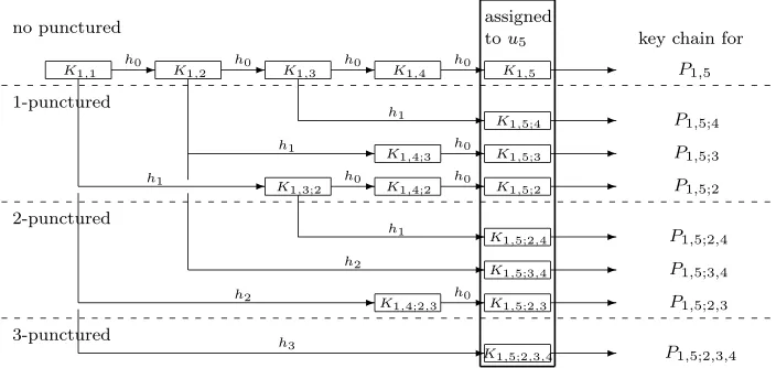
The following figure describes the key assignment in the scheme (3; 5)-π foru5:
- - - - -- -- - -- - - -- -- -- - -- -no punctured 1-punctured 2-punctured 3-punctured
key chain for assigned
tou5
P1,5
P1,5;4
P1,5;3
P1,5;2
P1,5;2,4
P1,5;3,4
P1,5;2,3
P1,5;2,3,4
K1,1 K1,2 K1,3 K1,4 K1,5
K1,5;4
K1,5;3
K1,4;3
K1,5;2
K1,4;2
K1,3;2
K1,5;2,4
K1,5;3,4
K1,5;2,3
K1,4;2,3
K1,5;2,3,4
h0 h0 h0 h0
h0 h0 h0 h0 h1 h1 h1 h1 h2 h2 h3
Fig. 3.One-way key chains starting fromK1,1, wherec= 5
Encryption For each session, the center divides L into disjoint p-punctured c -intervals P1, . . . , Pm ∈ S(p;c), whose union covers all the non-revoked users, under the rule described in Subsection 2.2. LetP =Pi,j;x1,...,xq be one ofPµ’s. The last key Ki,j;x1,...,xq of the key chain corresponding toP is called theinterval keyofP. Let’s
Then the center broadcasts :
hinfo1,info2, . . . ,infom;EK1(SK), EK2(SK), . . . , EKm(SK) ; ESK(M)i,
where infoµ is information on Pµ, theµ-th interval starting fromuiµ and ending at ujµ with qµ revoked users. For each µ, infoµ consists of iµ, `µ, `µ,1, . . . , `µ,qµ, where `µ=jµ−iµ+ 1 and`µ,1, . . . , `µ,qµ are the distances fromuiµ to the first, . . . , to the
last revoked users of Pµ, respectively. The starting position iµ can be represented
by logN bits and the`’s are at most logcbits. So the size of all info’s ism(logN+
plogc), which will be ignored when computing the transmission overhead because it is negligible compared to the size of allEK(SK)’s.
Decryption Receiving the encrypted message, each non-revoked user uk first
lo-cates the punctured interval that he/she belongs using the info’s. Let the punctured interval bePi,j;x1,...,xq, where i≤k≤j, k=6 x1, . . . , xq. Thenuk can findKi,j;x1,...,xq
as follows:
• Find t for which xt < k < xt+1, where 0≤t ≤q. Here, t = 0 and t= q mean that there is no revoked user before and after uk, respectively.
• Choose Ki,k;x1,...,xt from the assigned user keys.
• Starting from Ki,k;x1,...,xt, apply one-way permutation hi’s under the rule
de-scribed in Key Generation until the second subscript reaches to j. • The resulting key is then Ki,j;x1,...,xq.
With this, uk decryptsEKi,j;x1,...,xq(SK) andESK(M) to obtain the session key SK and the message M, respectively, in order.
2.4 Efficiency
We analyze efficiency - the transmission overhead, the computation cost and the storage size - of the scheme (p;c)-π.
The transmission overhead of the scheme (p;c)-π is
TO(p;c)(N, r) =
¹
r p+ 1
º
+
»
N −(p+ 2)br/(p+ 1)c
c
¼
,
whereN andr are the total number and revoked users, respectively.
In order to obtain this bound, we need the following theorem, which is proved in Appendix A.1.
Theorem 1. Let N and r be as above. Then the number of disjoint 1-punctured
c-intervals in S(1 ;c), constructed under the rule described in Subsection 2.2, is at most
TO(1 ;c)(N, r) =br/2c+
»
N−3br/2c
c
¼
.
In the scheme (2 ;c)-π, it can be easily shown by a similar argument that
T O(2 ;c)(N, r) =br/3c+
»
N−4br/3c
c
¼
and inductively, we can obtain the formula for TO(p;c)(N, r) We ignore the size of all info’s less thanm(logN+plogc) (bits), which is negligible.
It is trivial that the computation cost is at most c−1 computations of one-way permutations, that is,
CC(p;c)=c−1,
which is independent of N and r. The storage size of each user is
SS(p;c)=
p
X
k=0
Ã
1 (k+ 1)!
k+1
Y
i=1 (c−i)
!
+ 1,
which is also independent of N and r. The formula forSS(p;c) will also be proved in Appendix A.2.
2.5 Security
Note that even a non-revoked user cannot compute the interval keys of the other punctured intervals. Those who do not belong to any punctured interval are the revoked ones and they can never access to the session key. Neither those revoked users who belong to punctured intervals can access to their interval keys because they cannot invert the one-way permutations.
The only way to compute the interval key Ki,j;x1,...,xq ofPi,j;x1,...,xq is to obtain
one of the keys in the key chain explained in Subsection 2.3. However, no revoked user is assigned a key in the key chain and hence they cannot compute the interval key even though they all collude. Furthermore, the interval keys of previous sessions when the user was not revoked do not help at all in the present session, in which he/she is revoked, because the revocation of him/her results in a totally new key chain.
3 Practical Variances
The scheme (p;c)-πhas smaller transmission overhead than the best known schemes such as SD and LSD. But when the number r of the revoked users is smaller than
N
2c, our scheme is less efficient than SD. For practical purpose, this case should also
be considered. We introduce two variants of the (p;c)-π scheme whose transmission overhead is similar to that of SD if r is small, and to that of the (p;c)-π scheme otherwise.
3.1 Layered Punctured Interval Scheme
Layered Structure As in the (p;c)−π scheme, the set of all N users are ar-ranged on a long line L. Given a positive integer d (< logcN −1), we consider
d layers above the line L. The first layer L1 consists of N1 = dNce −1 users
u1, uc+1, . . . , u(N1−1)c+1. Inductively, the t-th layer Lt consists of Nt = d
Nt−1
c e −1
users u1, uct+1, . . . , u(N
t−1)ct+1 for 1 < t ≤d. We define layered intervals of length ct in the layer Lt by
LPi(t)={uk|(i−1)ct+ 1≤k≤ict}. (1)
Key Assignment First, the center assigns a random keyLKi(t)toLPi(t) for eachi
and gives it to all members ofLPi(t). Next, it constructs a one-way key chain starting from LKi(t). Let g1, . . . , gd:{0,1}` → {0,1}` be one-way permutations and h=h0 in (p;c)-π. Given kwith ict≤k≤(i+c−1)ct,LKi,k(t) is defined by
LKi,k(t) =he0 ◦ge1
1 ◦ · · · ◦gett(LK
(t)
i ) (2)
wherek−ict=etct+et−1ct−1+· · ·+e1t+e0 (0≤ei < c) is ac-ary expansion of
k−ict.
Let us consider the layered keys for the user uk in the t-th layer. Assume k =
etct+· · ·+e1c+e0 for 0≤e0, e1, . . . , et−1 < c and et≥0. Then the center takes j
withet+ 1−(c−1)≤j≤et+ 1 and gives to the user uk all the user keys LKj;kτ
wherek0=e0 and kτ =b(ckτ + 1)ccτ for 1≤τ ≤t.
The center assigns these keys to the user uk along with the interval keys for the
scheme (p;c)−π. Hence the total number of keys for each user is
SS(p;c)+
d
X
t=1
{(c−1)(t+ 1) + 1} ≤SS(p;c)+cd(d+ 3)
2 .
Encryption/Decryption If there is no layered interval consisting of all non-revoked users, the center encrypts the session key just as in the scheme (p;c)-π. Otherwise, we can save the transmission overhead by using layered keys. First the center marks all the layered intervals at each layer which has at least one revoked user as revoked intervals. Next, it finds the leftmost non-revoked interval, sayLPi(d), in thed-th layer. Then the session key is encrypted byLKi,k(d), whereuk+1 is the first revoked user after uicd withk≤(i+c)cd. The center then marks all the users from u(i−1)ct+1 touk and the layered intervals containing at least one of them revoked.
This process is repeated for the next non-revoked interval. If there is no non-revoked interval in thed-th layer, go to (d−1)-st layer and repeat the same procedure and so on. Finally, if all layered intervals at each layer are revoked, then the scheme (p;c)-π is applied for the remaining non-revoked users.
Note that each non-revoked user uk can decrypt the session key by an interval
Transmission Overhead First we estimate the transmission overhead for (p;c
)-π1. If there is no revoked user, then dNc2e layered intervals cover entire straight line
L. By inserting one revoked user to an interval, the interval is divided to at most 3 intervals including punctured or long intervals. So the transmission overhead is at mostdNc2e+ 2r. Trivially, the transmission overhead of this scheme cannot be larger
than that of punctured interval scheme. So we can conclude that the transmission overhead is at mostM in{dNc2e+ 2r ,dr2e+
l
N−d3r/2e
c
m
}.
Theorem 2. The(p;c)-π1 scheme with r revoked users amongN=cd+1 users has
M in{dcN2e+ 2r , dr2e+
lN−d3r/2e
c
m
} transmission overhead.
The transmission overhead of (p;c)-πd ford ≥2 can be similarly estimated. That
is, for small r, the graph is a dashed line with a steeper slope starting at (0,dNc2e)
3.2 Tree based Punctured Circle Scheme (TPC scheme)
We can easily modify a linear structure to a circular structure by bending and gluing two ends of a line. If we glue two ends of ap-puncturedc-interval, we can make ap -puncturedc-circle. So from our (p;c)-π scheme, we can obtain ap-puncturedc-circle scheme in which the user index is defined moduloc with the set of representatives {1,2, . . . , c}. For example, in the 0-punctured c-circle scheme the one-way key chain starting from ui is
Ki,i, Ki,(i+1 modc)=h(Ki,i), . . . , Ki,(i+c−1 modc) =hc−1(Ki,i).
In ap-punctured c-circle, we define an intervaland aninterval key to be those of a
p-puncturedc-interval by fixing a starting node. We assume than the each circle has one special node. The starting node is the special node if there is no revoked user in the circle, or the next node of the first revoked node otherwise. The key assignment, encryption and decryption are similar to those of the (p;c)-π scheme.
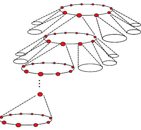
This variant itself has no remarkable advantage over the scheme (p;c)-π. But if we combine this idea with tree structure then we can reduce the transmission overhead further. Let us consider a completec-ary tree of depth d+ 1 such that all children of each internal node at each level form a circle with c points at the next level. The root node is considered in level zero. Each user is assigned to one leaf node of the tree. The node keys are assigned to the nodes in a circle in level t by the 0-puncturedc-circle scheme if 1≤t < d, and by thep-puncturedc-circle scheme ift=d. And each user is given all the keys assigned to its ancestor nodes. So, the storage size of each user equals toSS(p;c)+c(d−1).
…
Fig. 4.Structure of tree based circles
With this variation, we lose an advantage of the (p;c)-πscheme that user addi-tion is easy even after the system launches. However, (p;c)-TPC scheme has slightly better performance than the (p;c)-πdscheme whenr is small. Especially, the
com-putation cost isc−2 computations of one-way permutations which is much smaller than that of the (p;c)-πdscheme. The transmission overhead appears to be a
piece-wise linear function of r such that f(0) = 1, f(ct/2) = 1
2ct(d−1) for 0≤t≤d−1 and f(r) =r/2 + 34Nc when r ≥ cd2−1. The detailed complexity is given below. The proof can be found in Appendix A.3.
Theorem 3. The(p;c)-TPC scheme with r revoked users among N=cd users has the following transmission overhead:
TO=
dr if r≤c/2
..
. ...
(d−t)r+c
t
2 if c
t/2< r≤ct+1/4 for 1≤t≤d−2
(d−t)r+c
t
2 −
»
r−ct+1/4
c/2
¼
if ct+1/4< r≤ct+1/2 for 1≤t≤d−2 ..
. ...
r p+ 1+
2p+ 1 2p+ 2c
d−1 if cd−1/2< r
4 Discussion
4.1 Comparison
is 0.1,0.5,1,5,10 and 20% ofN. In the table, we assume that every user key is 128 bits.
Table 1.Examples whenN= 108
Scheme Storage TO (Mbits) CC
rrevoked (KBytes) 0.1% 0.5% 1% 5% 10% 20% (0; 100)−π 1.60 141 191 253 755 1380 2640 100 (1; 100)−π 79.2 134 159 190 438 749 1370 100 (0; 100)−π1 4.80 26.9 129 253 755 1380 2640 198
(1; 100)−π1 82.4 26.9 129 190 438 749 1370 198
(0; 100)-TPC 6.40 26.2 128 192 704 1340 2624 99 (1; 100)-TPC 84.0 26.2 128 160 416 736 1380 99
SD 11.7 25.6 128 256 1280 2560 5120 27
LSD 2.24 51.2 256 512 2560 5120 10240 27
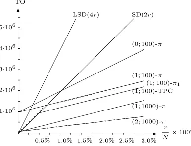
Figure 5 shows the comparison of the worst-case transmission overheads by graphs when the revocation rate ranges from 0% to 3%. Among the graphs, the dotted line represents the transmission overhead of the scheme (1 ; 100)-π1. The dotted graph is very close to that of SD for small r. It has steeper slope than the graph of (1; 100)-π, but a lower y-intercept at dNce. As we mentioned above, the layered π scheme improves the transmission overhead when the revocation rate is small. For large r, it has the same transmission overhead as that of the scheme (p;c)-π.
Figure 6 is the comparison of theaverage-casetransmission overhead. This com-parison is done by computer simulation by randomly choosing revoked users. Note that the average-case transmission overhead is 1.25r for SD,r for the (0, c)−π and asymptotically 0.5r for (1 ; c)−π and (1 ; c)−π1. Generally, it approaches to r/p for (p;c)-π.
- r N×100%
6
TO
-1·106
-2·106
-3·106
-4·106
-5·106
0.5% 1.0% 1.5% 2.0% 2.5% 3.0%
¡¡ ¡¡ ¡¡ ¡¡ ¡¡ ¡¡
SD(2r)
¢¢ ¢¢ ¢¢ ¢¢ ¢¢ ¢¢
LSD(4r)
©©©©
©©©©
©©©© ©
(0; 100)-π
»»»»»»
»»»»»» »
(1; 100)-π
(1; 100)-TPC (1; 100)-π1
»»»»»»
»»»»»
((((((((((
(((
(1; 1000)-π
»»»»»»
»»»»»» »
(2; 1000)-π
Fig. 5.TO forN= 1·108 in the worst case
- r N×100%
6
TO
-1·106
-2·106
-3·106
-4·106
-5·106
0.5% 1.0% 1.5% 2.0% 2.5% 3.0%
""""
""""
"""" ""
SD 1.25r
»»»»³³³³³³
³³³³!! !!!!
(0; 100)-π
b b b b b
b b
b b
((((((((((((((
(1; 100)-π
p r r r r r r r r
""©©!!³
³»»»ÃÃÃÃà ÃÃÃÃ
♦(1; 100)-π1 ♦ ♦ ♦ ♦ ♦ ♦ ♦ ♦ ♦ »»»»»»ÃÃÃÃà ÃÃÃÃÃÃÃÃÃ
4(1; 100)-TPC
4 4 4 4 4 4
4 4 4
4.2 Practical Considerations
User Addition Our broadcast schemes (p;c)-π and (p;c)-πd have a great
ad-vantage for user additions. In SD or LSD, once the system has launched, no user can be added without updating the user keys. Thus, all potential users should be considered when the system is designed, because the system can be out of service if more users than the preset number are joined. On the other hand, our scheme
π allows any number of user additions without changing the keys of the previous users. To add one new user to the system, the center places him/her at the end of the line, computes the corresponding keys and sends them to the user. This process requires neither interaction nor key update of other users. Note that the (p;c)-TPC scheme does not have this property.
User Replacement User replacement is a more complicated problem than user addition. User replacement is to remove a permanently revoked user, and add a new user at that position. In general, user replacement is not possible without user key update, which is not allowed for many systems. But when it is allowed, the (p;c)-π
scheme can perform the replacement with small overhead : One replacement requires key update of at most 2c−1 users. For the (p;c)-π1 scheme, it becomes 2c2−1. In the (p;c)-TPC, all users must update at least one user key as in SD and LSD.
Flexibility On the contrary of the tree-based schemes, our scheme possesses lots of flexibility of system performance. By varying the system parameter, one can achieve very small transmission overhead or very small storage size. If the storage size and the computation cost are restricted as in smart cards, we may use the (0;c)−π scheme with small c which requires for each user to store only c keys. The computation costs are at mostc−1 computation of one-way permutations. For example, if we take c = 20, it requires only 20 keys for each user and at average 9.5 computation of one-way permutations for each session while the transmission overhead is r+dN20−re. In [8] logk restriction was introduced for the storage size. Our scheme is bits in as good as any other schemes to this restriction. On the other hand, if the user device allows large storage like set-top boxes, PC’s and CD or DVD players, and the transmission is expensive, then one can use (p;c)-πd scheme for
largec, in which the transmission overhead approaches rapidly to r/p.
5 Conclusion
In this paper, we proposed a broadcast encryption scheme based on the idea ‘one key forp-punctured c-interval’. Our scheme has about 1/3 transmission overhead than SD when p = 1. For the case of small revoked users, we proposed two variants of our scheme: one is based on layer structure and the other is based on tree structure. Both have about the same complexity as SD for smallr.
Moreover, our scheme has some additional properties. First, the user addition is free without any key update of the previous users. Second, we have many flexibility on the system efficiency. The system can be optimized to have best efficiency for any of the three parameters of broadcast encryption the transmission overhead, the computation cost and the storage size.
The (p;c)-π scheme has asymptotically r/ptransmission overhead. It would be interesting to design a broadcast encryption scheme with r² transmission overhead for² <1, if not logr.
References
1. J. Anzai, N. Matsuzaki and T. Matsumoto, A quick key distribution scheme with “Entity Re-vocation”, Advances in Cryptology - Asiacrypt’99, Lecture Notes in Computer Science 1716, pp.333-347.
2. S. Berkovits,How to Broadcast a secret, Advances in Cryptology - Eurocrypt’91, Lecture Notes in Computer Science 547, pp.536-541.
3. D. Boneh and A. Silverberg,Applications of Multilinear Forms to Cryptography, Contemporary Mathematics 324, American Mathematical Society, pp.71-90.
4. B. Chor, A. Fiat and M. Noar,Tracing Traitors, Advances in Cryptology CRYPTO’94, Lecture Notes in Computer Science 839, pp. 257-270.
5. G. Chick and S. Tavares, Flexible access control with master keys, Advances in Cryptology -Crypto’89, Lecture Notes in Computer Science, pp.316-322.
6. P. D’Aroco and D.R. Stinson,Fault Tolerant and Distributed Broadcast Encrytion, CT - RSA’03, Lecture Notes in Computer Science 2612, pp.263-280.
7. A. Fiat and M. Naor,Broadcast Encryption, Advances in Cryptology - Crypto’93, Lecture Notes in Computer Science 773, pp.480-491.
8. M.T. Goodrich, J.Z. Sun and R. Tamassia,Efficient Tree-Based Revocation in Groups of Low-State Devices, Advances in Cryptology - Crypto’04, Lecture Notes in Computer Science 3152, pp.511-527.
9. J. Garay, J. Staddon and A. Wool,Long-Lived Broadcast Encryption, Advances in Cryptology -Crypto’00, Lecture Notes in Computer Science 1880, pp.333-352.
10. E. Gafni, J.staddon and Y.L. Yin,Efficient Methods for Integrating Traceability and Broadcast Encryption, Advances in Cryptology - CRYPTO’99, Lecture Notes in Computer Science 1666, pp.372-387.
11. D. Halevi and A. Shamir,The LSD Broadcast Encryption Scheme, Advances in Crytology -Crypto’02, Lecture Notes in Computer Science 2442, pp.47-60.
12. R. Kumar, S. Rajagopalan and A. Sahai,Coding Constructions for blacklisting problems without Computational Assumptions, Advances in Cryptology - Crypto’99, Lecture Notes in Computer Science 1666, pp.609-623.
13. D. Naor, M. Naor and J. Lotspiech,Revocation and Tracing Schemes for Stateless Receivers, Advances in Cryptology - Crypto’01, Lecture Notes in Computer Science 2139, pp.41-62. 14. M. Naor and B. Pinkas,Efficient Trace and Revoke Schemes, Financial Cryptography’00,
Lec-ture Notes in Computer Science.
15. C.K. Wong, M. Gouda and S.S. Lam,Secure Group Communication using Key Graphs, ACM SIGGCOM’98 ACM.
Appendix
A.1 Transmission Overhead of (p;c)-π
We regard N users on the line L as a string in {0,1}N, where revoked and non-revoked users are represented by 0’s and 1’s, respectively. Let
– S: the set of all strings of 0’s and 1’s of lengthN
– T1||T2: the concatenation of stringsT1 and T2 – |S|: the length of a string S
– |S|i: the number of i’s in a string S, wherei∈ {0,1}
Let A(1;c) be the following algorithm : – Input:S ∈S
– Output:A(1;c)(S) ={S1, S2, . . . , Sm}, whereSµ’s are 1-puncturedc-intervals (in
S(1;c)) determined under the rule described in Subsection 2.2 such that
S =O0||S1||O1||S2||O2|| · · · ||Sm||Om
for suitable Oµ’s, strings of 0’s of length ≥0.
Definition 1. Given S, S0 ∈S, we define S ≤
(1;c) S0 if |A(1;c)(S)| ≤ |A(1;c)(S0)|, and S≡(1;c) S0 if S ≤(1;c)S0 and S0 ≤(1;c)S .
Definition 2. Given a stringS ∈S, O||A||I is called a reduced form of S if
(1) S≤(1;c) O||A||I
(2) |S|=|O|+|A|+|I|and |S|1 =|A|1+|I|
where A is a string of ‘100’ possibly with ‘10’ at the end, O is a string of 0’s and I
is a string of 1’s.
We now introduce an algorithm that find a reduced form for any string S ∈S.
Let S ∈S,A(1;c)(S) = {S1, S2, . . . , Sm} and S =O0||S1||O1||S2||O2|| · · · ||Sm||Om.
Note that every Sµ ∈ A(1;c)(S) contains at most one 0 in its interior between 1’s. Suppose|Oµ|=n≥3 for some 1≤µ < m. Then
O0|| · · · ||Sµ||0n||Sµ+1|| · · · ||Om ≡(1;c) 0n−2||O0|| · · · ||Sµ||Sµ+1|| · · · ||Om.
Similarly,
O0||S1|| · · · ||Sm||Om ≡(1;c)Om||O0||S1|| · · · ||Sm.
The numbers of 0’s and 1’s in both sides are the same, respectively, for both formulas above. So we may assume that Om is an empty string and |Oµ| ≤ 2 for each 1 ≤
µ < m while O =O0 absorbs all those exceeding 0’s. We now let S0µ=Sµ||Oµ for
1≤µ≤m.
Reduction Algorithm
– Input:S ∈S
1. m=|A(1;c)(S)|
2. T =A=I: empty strings 3. While m >0
while |T|0<2 andm >0
T =S0m||T m=m−1
reduction 1 (if|T|0 = 2)
while T = 1i01j01k orT = 1i001j
A0= 100
T = 1i+j+k−1 orT = 1i+j−1, resp. reduction 2 (if|T|0 = 3)
while T = 1i01j01k01l orT = 1i001j01k or 1i01j001k
A0= 100
T = 1i01j+k+l−1 orT = 1i+j−101k or 1i01j+k−1, resp. reduction 3 (if|T|0 = 4)
while T = 1i01j001k01l
A0= 100100
T = 1i+j+k+l−2
A=A||A0
4. While |T|0 = 1 (i.e.,T = 1i01j)
A=A||10
T = 1i+j−1
5. Output O||A||I, where I =T
Lemma 1. The output string O||A||I of the reduction algorithm is a reduced form of the input string S.
Proof. Observe that the string O is the collection of all 0’s that have no influence on the number of 1-punctured c-intervals of S. Each string ‘100’ in A corresponds to a 1-punctured c-interval of the form ‘10’. The value d(|I|+ε)/ce is the number of 1-puncturedc-intervals in I or in 10||I whenε= 0 or 2, respectively. Here,ε= 0 or 2 if A ends with ‘100’ or ‘10’, respectively. So the total number of 1-punctured
c-intervals is
|A(1;c)(O||A||I)|= |A| −ε
3 +
»
|I|+ε)
c
¼
.
This number is obviously bigger than or equals to |A(1;c)(S)| because in each reduction step in the reduction algorithm the number of 1-punctured c-intervals is non-decreasing. Furthermore, the numbers of 0’s and 1’s in S and in O||A||I are kept same, respectively. This prove that the outputO||A||I is a reduced form of the
input S. ut
string, that is,Sis of the formA||I. The number of 0’s inSisrand all are contained in A. Since each string ‘100’ determines a 1-punctured c-interval of the form ‘10’, every two 0’s corresponds to one 1-punctured c-interval. There may be one more 0 from the string ‘10’ at the end of A. So, the number of 1-punctured c-intervals corresponding to ‘100’s inAisbr/2c. Now the remaining string on the right is either
I or 10||I, whose length is exactly N −3br/2c. Since this string contains at most one 0, it contains exactlyd(N−3br/2c)/ce1-punctured c-intervals. This proves the theorem.
A.2 Storage Size of (p;c)-π
We count the number of keys of the form Ki,k;X for the user uk. Let νs denote
the number of keys of the form Ki,k;X with|X|=s.
– ν0 =c – ν1
the number of new keys in the chain of length c :c−2 the number of new keys in the chain of length c−1 : c−3
. . .. So,
ν1 = (c−2) + (c−3) +· · ·+ 1 =
(c−1)(c−2)
2 =
µ
c−1 2
.
– ν2
the number of new keys in the chain of length c :
¡
c−22¢
the number of new keys in the chain of length c−1 :¡
c−23¢
. . .. So,
ν2=
µ
c−2 2
+
µ
c−3 2 ¶ +· · ·+ µ 2 2 
= (c−1)(c−2)(c−3)
6 =
µ
c−1 3
.
– In general,
νp=
µ
c−2
p
+
µ
c−3
p ¶ +· · ·+ µ p p ¶ = 1
(p+ 1)!
p+1
Y
t=1
(c−t) =
µ
c−1
p+ 1
.
Therefore the storage size of the scheme (p;c)-π is
SS(p;c)=
p
X
k=0
νk= p
X
k=0
Ã
1 (k+ 1)!
k+1
Y
i=1 (c−i)
!
+ 1 =
p+1
X
k=0
µ
c−1
k
.
A.3 Transmission Overhead in (p;c)-πd
Consider the followings:
1. Assume that up to t-th layer are used.
3. Revoking one user the number of intervals is increased by at most t+ 1, where
r ≤cd−t+1/2.
4. So T O≤N/ct+ (t+ 1)r =cd−t+1+ (t+ 1)r.
This is a rough bound with restricted range of r. We can conclude that the transmission overhead of (p;c)-πdfor specificris less than or equal to the minimum
value of such bounds for r.
A.4 Transmission Overhead in TPC
Proof of Theorem 3. If there is no revoked user, then with one subset the center can send session key to all users. If r = 1, then there is one revoked node in each level(total d subset is required). When another user is revoked, the worst case is that two revoked users have no common ancestor and the ancestors in the first level are not neighbor of each. In this case total 2dsubsets are required. In this manner, we obtain the first formula for 1≤r≤c/2.
We can obtain the second and the third formulas using induction on t. Assume that they hold for t < τ. So, r=cτ/2 implies that
T O≤(d−τ + 1)r+ c
τ−1 2 − d
r−cτ/4
c/2 e= (d−τ + 1)
cτ
2.
Whencτ/2< r≤cτ+1/4, the worst case is when all circle in theτ-th level contains
c/2 revoked nodes and c/2 non-revoked users alternatively (this circle is called a saturated circle), and new revoked user is inserted to the (τ+1)-st level. The revoked user is inserted to the τ-th level means that when one revoked user is inserted in a tree, the highest ancestor of the revoked which is changed to revoked node is in the
τ-th level. For each inserted revoked user,d−τ more subsets are needed. So,
(d−τ+ 1)c
τ
2 + (d−τ)(r−
cτ
2 ) = (d−τ)r+
cτ
2 and r=cτ+1/4 implies that
T O≤(d−τ)r+c
τ
2 = (d−τ)
cτ+1
4 +
cτ
2.
When cτ+1/4 < r ≤ cτ+1/2, the worst case is as follows: The first additional revoked user is inserted to the τ-th level so that there is only one circle in the (τ + 1)-st level which contains revoked node but not saturated. Next (c/2)−1 revoked users are inserted to the (τ+ 1)-st level to make the above circle saturated. As a result of inserting, all nodes of the τ-th level are revoked and all circles of the (τ + 1)-st level are saturated. So,
T O ≤(d−τ)c
τ+1
4 +
cτ
2 + (d−τ)(r−
cτ+1
4 )− d
r−(cτ+1)/4
c/2 e
= (d−τ)r+c
τ
2 − d
r−(cτ+1)/4
Since the d-th level uses p-punctured scheme, the formula is different from the above levels. In thed-th level, forp+1 revoked users, one subset is needed. Therefore,
T O≤cd−1+ 1
p+ 1(r−
cd−1
2 ) =
r p+ 1+
2p+ 1 2p+ 2c