169 | P a g e
www.ijarse.com
PROBLEMS OF POWER QUALITY WITH THE
MITIGATION BY USING
HYBRID
ACTIVE
POWER
FILTER
FOR
THREE
PHASE
SYSTEM
1
Kratika Karnwal,
2D.V.Awasthi
1
M-tech Student,
2Associate Professor, Dept. of PED
Subharti Institute of Tech. Education, Meerut (India)
ABSTRACT
Power Quality has become the buzzword in today’s environment of power electronics, digital communication and automation industry based on digital circuitry. Greater sensitivity of devices and equipment to power quality variations, interconnection of sensitive loads in extensive networks and automated processes, and an increase in the loads that use power electronics in many of the power conversion processes have made power quality imperative for industries and the market. The perception of PQ is quite different among different stakeholders namely, the regulator, the consumer, the network operator and the device manufacturer. Consequently, there are increasing number of disputes on PQ issues and individual responsibility of the stakeholders on PQ all over the world. The practical solution to all these problems, however, is to be based on overall impacts of the PQ related issues.
The Paper gives an overview of the problems related to the power quality & this paper also presents an implementation of hybrid active power filter for decreasing the distortions in currents in a three phase systems.
Keywords: Power Quality Problems, Hybrid Active Power Filter For 3-Ph System, Simulink
Model with Result
I. INTRODUCTION
“The concept of powering and grounding sensitive electronic equipment in a manner suitable for the
equipment” & “as the ability of a system or an equipment to function satisfactorily in its electromagnetic
environment without introducing intolerable electromagnetic disturbances to process operation in the
industrial process or system” these are the definitions of Power quality according to the IEEE Standards. PQ
covers two broad issues namely: 1.Interruption free power supply which means Reliability of Power supply
2. The constant voltage and frequency of power implying Power Quality. PQ presumes 100% reliability.
Power quality, or more specifically, a power quality disturbance, is generally defined as any change in power
(voltage, current, or frequency) that interferes with the normal operation of electrical equipment. The
standard (IEEE Standard 1159-1995, "IEEE Recommended Practice for Monitoring Electrical Power
Quality") describes many power quality problems, of which this paper will discuss the most common.
170 | P a g e
www.ijarse.com
quality problems which could relate to harmonics affecting communication interference, heating,
solid-state devices malfunction, resonance. Solutions involve several techniques that include the
use of passive and active power filter (APF). A more advance approach is the use of hybrid filters
amongst other involves the use of both the passive filter and shunt APF in combination. They are
being used to eliminate both the lower order and higher order harmonics. The passive filter is
normally designed to eliminate the bulk of load-current harmonic leaving the more complex
problems to be solved by the APF. Shunt APF normally operates using pulse width modulation
(PWM) inverter techniques to inject the required non-sinusoidal current requirements of
nonlinear loads but is complex with the number of switches in use. Another approach is the use of
series active power filter that uses basic bridge-diode circuit, boost circuit and an inductor. Single phase
converter produces a relatively high proportion of ac ripple voltage at its dc terminal, it is undesirable
becau se of its heat producing effect. A smoothing needed to get continuous operation. It can be
minimized by increasing number of pulses. Three phase ac supply with a suitable transformer
connection permits an increasing the pulse number. When the number of pulses increased out-put
voltage gets smoothen. So here we are implementing an extension of single phase hybrid active power
filter with three phases HAPF. The time-domain approach is used to control the power switch of
proposed PAPF during compensation process. This approach is based on the principle of holding
the instantaneous current within some reasonable tolerance of a sine wave. The error is computed from
the difference of instantaneous actual current signal with its reference signal, normally pure sine
wave. This error is then conditioned and processed to obtain the required switching pattern known
as the pulse wave modulation (PWM) wave. A simple proportional integral control method is
implemented to aid response from the control which uses a supply current detection to accomplish
shunt APF tasks. A simple LC filter is used in conjunction to study its effects.
II. PROBLEMS RELATED TO POWER QUALITY
IEEE Standard 1159-1995 also addresses these problem with the goal of providing consistent terminology for
power quality reporting from the professional community. Some of these ambiguous terms are described in
this paper as follows:
2.1 Blackouts
Description: It is short or long term loss of electric power to an area.
Causes: Faults at power stations, Damage to electric transmission lines, substations or other parts of the
distribution system, Short circuit, or the overloading of electricity mains.
Effects: Total loss of power to an area, tripping of substations, under certain conditions, a network
component shutting down can cause current fluctuations in neighboring segments of the network leading to
a cascading failure of a larger section of the network. This may range from a building, to a block, to an
171 | P a g e
www.ijarse.com
2.2 Brownouts
Description: A brownout is an intentional or unintentional drop in voltage in an electrical power supply
system.
Causes: Use of excessive loads causes reduction in voltage which in turn causes brownouts.
Effects: Unexpected behavior in systems with digital control circuits & The system can experience glitches,
data loss and equipment failure.
2.3 Voltage Sag (or Dip)
Description: A decrease of the normal voltage level between 10 and 90% of the nominal rms voltage at the
power frequency, for durations of 0.5 cycle to 1 minute.
Causes: Faults on the transmission or distribution network (most of the times on parallel feeders). Faults in
consumer’s installation. Connection of heavy loads and start-up of large motors.
Consequences: Malfunction of information technology equipment, namely microprocessor-based control
systems (PCs, PLCs, ASDs, etc) that may lead to a process stoppage. Tripping of contactors and
electromechanical relays. Disconnection and loss of efficiency in electric rotating machines.
2.4 Very Short Interruptions
Description: Total interruption of electrical supply for duration from few milliseconds to one or two
seconds.
Causes: Mainly due to the opening and automatic enclosure of protection devices to decommission a faulty
section of the network. The main fault causes are insulation failure, lightning and insulator flashover.
Consequences: Tripping of protection devices, loss of information and malfunction of data processing
equipment. Stoppage of sensitive equipment, such as ASDs, PCs, PLCs, if they’re not prepared to deal with
this situation.
2.5 Long interruptions
Description: Totalinterruption of electrical supply for duration greater than 1 to 2 seconds
Causes: Equipment failure in the power system network, storms and objects (trees, cars, etc) striking lines
orpoles, fire, human error, bad coordination or failure of protection devices.
Consequences: Stoppage of all equipment.
2.6 Voltage Spikes
Description: In electrical engineering, spikes are fast, short duration electrical transients in voltage.
Causes: Lightning strikes, Power outages, Tripped circuit breakers, Short circuits
Effects: Voltage spikes may be created by a rapid buildup or decay of a magnetic field, which may induce
energy into the associated circuit.
2.7 Voltage Swell
Description: Momentary increase of the voltage, at the power frequency, outside the normal tolerances,
with duration of more than one cycle and typically less than a few seconds.
Causes: Start/stop of heavy loads, badly dimensioned power sources, badly regulated transformers (mainly
172 | P a g e
www.ijarse.com
Consequences: Data loss, flickering of lighting and screens, stoppage or damage of sensitive equipment, if
the voltage values are too high.
2.8 Harmonic distortion
Description: Voltage or current waveforms assume non-sinusoidal shape. The waveform corresponds to
the sum of different sine-waves with different magnitude and phase, having frequencies that are multiples
of power-system frequency.
Causes:Classic sources: electric machines working above the knee of the magnetization curve (magnetic
saturation), arc furnaces, welding machines, rectifiers, and DC brush motors.
Modern sources: all non-linear loads, such as power electronics equipment including ASDs, switched mode power supplies, data processing equipment, high efficiency lighting.
Consequences: Increased probability in occurrence of resonance, neutral overload in 3-phase systems,
overheating of all cables and equipment, loss of efficiency in electric machines, electromagnetic
interference with communication systems, errors in measures when using average reading meters, nuisance
tripping of thermal protections.
2.9 Voltages Surges
Description: It is a voltage rise that endangers the insulation of electric equipment.
Types :
1. Lightning surges.
2. System-generated surges.
Causes: Shutdown of heavily loaded circuits. Necessary commutation of a high-powered network (e.g. Pf
correction) & Switching events such as the connection or disconnection of a current and short-circuiting to
ground.
Effects: Computers and other sensitive electronic equipment can seriously be damaged by such an
over-voltage surge & Temporal fluctuations produce parity errors and interrupts protection systems.
2.10 Flicklings
Description: It is a visible change in brightness of a lamp due to rapid fluctuations in the voltage of the
power supply.
Causes: It increase as the size of the changing load becomes larger with respect to the prospective short
circuit current available at the point of common connection.
Effects: Filament of lamp can be damaged & Reduction in life of electrical equipment
2.11 Voltage Fluctuation
Description: Oscillation of voltage value, amplitude modulated by a signal with frequency of 0 to 30 Hz.
Causes: Arc furnaces, frequent start/stop of electric motors (for instance elevators), oscillating loads.
Consequences: Most consequences are common to undervoltages. The most perceptible consequence is the
flickering of lighting and screens, giving the impression of unsteadiness of visual perception.
2.12 Voltage Unbalance
Description: A voltage variation in a three-phase system in which the three voltage magnitudes or the phase
173 | P a g e
www.ijarse.com
Causes: Large phase loads (induction furnaces, traction loads), incorrect distribution of all
single-phase loads by the three single-phases of the system (this may be also due to a fault).
Consequences: Unbalanced systems imply the existence of a negative sequence that is harmful to all three
phase loads. The most affected loads are three-phase induction machines.
III. MITIGATION BY USING HYBRID ACTIVE POWER FILTER WITH THE HELP OF
REMOVING HARMONICS
The indiscriminate use of non-linear loads has given rise to investigation into new compensation equipment
based on power electronics. The aim of this equipment is the elimination of harmonics in the system and
reduction in reactive power flow. Depending on application type, series or parallel configurations or
combination of active and passive filters are used. Active power filters can be used in conjunction with
passive filters improving compensation characteristics of the passive filter and to avoid the possible
occurrence of the generation of series or parallel resonance. If the passive filters are not connected, the active
power filter could compensate only voltage regulation and voltage unbalance. The best method is to combine
the compensation characteristics of passive and active power filters, as shown in Fig. 1 which is Hybrid
Filter. In this way, the compensation characteristics of the passive filter is significantly improved since the
active scheme generated voltage harmonic components across the terminal of the primary windings of the
series transformer, forcing current harmonics generated by the load to circulate through the passive filter
instead of the power distribution system. By controlling the amplitude of the voltage fundamental
component across the coupling transformer, the power factor of the power distribution system can be
adjusted. However, the control of the load power factor imposes a higher voltage across the filter capacitor.
This effect has to be considered when the filter capacitors are specified. This type of configuration is very
convenient for compensation of high power medium voltage non-linear loads, such as large power ac drives
with cycloconverters or high power medium voltage rectifiers for application in arc furnaces.
The new proposed hybrid APF consists of two types of filter,
Active Power Filter
Passive Power Filter
IV. ACTIVE POWER FILTER
4.1 Shunt Active Power Filter
The more usual APLC configuration is the shunt or parallel connection. Figure 1 shows the basic scheme of the
connection, where an IGBT switching device represents the APLC power block. The loads with current
harmonics can be compensated by this APLC configuration. A typical example of a current- source load is a
rectifier with resistive branch in dc side. Figure 1 shows the basic performance of a shunt APLC. The general
aim is that the shunt APLC will inject into the system a compensation current, iC, to cancel the harmonic
component of the load current, iL. The source current iS becomes sinusoidal after the compensation.
The current waveform of a nonlinear load, a three-phase diode rectifier with a highly inductive DC branch, is
174 | P a g e
www.ijarse.com
with the load. Figure 2d shows the source current of the system. Before the compensation is equal to the current
load, and after it is sinusoidal. In this example, the source voltage is sinusoidal,Figure2a.
4.2 Series Active Power Filter
Figure 3 shows the connection scheme of a series APLC. It is connected to the system through a coupling
transformer. The compensation voltage, vC, is used to cancel the voltage harmonics of the load, e.g. diode
rectifiers with high capacitance in the DCside.
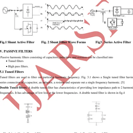
Fig.1 Shunt Active Filter Fig. 2 Shunt Filter Wave Forms Fig3 . Series Active Filter
V. PASSIVE FILTERS
Passive harmonic filters consisting of capacitors, inductors, and resistors can be classified into
Tuned filters
High pass filters.
5.1 Tuned Filters
Tuned filters are used to filter out particular harmonic frequency. Fig. 3.1 shows a Single tuned filter having
series connection of a capacitor, an inductor, a resistor and separate out a single frequency harmonic. [5]
Double Tuned filters: A double tuned filter has characteristics of providing low impedance path to 2 harmonic
frequencies. It has advantage of low loss at the lower frequencies. A double tuned filter is shown in fig.4
Fig.3.1. A Single Tuned Filter. Fig.4. Double Tuned Filter
5.2 High Pass Filter:
The characteristic of high pass filters is to offer low impedance path to all the high frequencies. Fig.5 shows
175 | P a g e
www.ijarse.com
C-Type High pass filter:
Fig. 6 shows a C-type high pass filter having a capacitor in series with the inductor which provides low
impedance path to low frequencies. This helps in reducing the loss at low frequencies. Fig.6 shows C-type
HPF
Fig.5. High Pass Filter. Fig.6. C-Type High Pass Filter.
Passive filters are connected in parallel with nonlinear loads such as diode/thyristor rectifiers, ac electric arc
furnaces, and so on. Among them, the combination of four single-tuned filters to the fifth, seventh, 11th and
13th-harmonic frequencies and a second-order high-pass filter tuned around the 17th-harmonic frequency has
been used in a high-power three-phase thyristor rectifier. The drawback of passive filters is that they create
resonance condition at particular frequencies they are intended to work for. This raises the magnitude of
harmonic voltages at that particular frequency.[8]
VI. HYBRID FILTER
Figure 7 shows some of the hybrid passive and active filters. The basic aim of these combinations is to reduce
the cost of the static compensation. The passive filters are used to cancel the most relevant harmonics of the
load, and the active filter is dedicated to improving the performance of passive filters or to cancel other
harmonics components. As result, the power of the active filter is reduced, and the passive filter problems (e.g.
resonances with the source impedance) are mitigated. In summary, the total cost decreases without reductionof
the efficiency.
Fig7. Hybrid filter
VII. SIMULATION MODEL
176 | P a g e
www.ijarse.com
shows the proposed system that consists Hybrid Filter with H APF shunt-connected with the non-linear
load and main supply. A gate drive circuit was used to boost the small PWM signal into an
appropriate level for turning ON of the IGBT and to provide physical isolation between the power
and electronics section.
Fig.8 HAPF Simulink Model
VIII. SIMULATION
RESULTS
Selected simulations results on the operation of the proposed hybrid active power filter
arrangements are presented. The behaviour of the supply subject to non-linear load is investigated
in four modes of operation; without filter, b) with passive filter c) with APF and d) with hybrid. Fig.
8 show results obtained from simulation. In this project without using any rectifiers. The output voltage
and currents gets distorted in phase shifts or out of phase. So, the total harmonic distortion values is on
the range of 38% to 42%.by connecting simple passive filter half of its means 20% to 24% to reduced. by
adding active power filter thd value reduced to 10% to 12%.finally by implementing hybrid active power
filter means combination of both active and passive filters the thd value reduced to below 4.36% which is to
be economical.
Fig.9.Dc Component Current, Load Current & Source Current without Filtration
HYBRID AP FILTER
PCC
HAP FILTER for 3 phase 4 wire systems
Discre te , Ts = 5e -006 s.
powe rgui A B C A B C Zt Vabc Iabc A B C a b c V-I meas.
A B C a b c
Scope4 Scope3 Scope2 I_load a b c Non Li near Load
i + -Id1 Icomp* a b c HYBRID AP FILT ER
177 | P a g e
www.ijarse.com
Fig.14 Output Current Without Harmonics Distortion
Comparision
Type of Filter THD Value
Without Filter 38%
Passive Filter 10.82%
Active Filter 7.83%
Hybrid Active Filter 4.36%
IX. CONCLUSION
This work has illustrated that the single-switch could be used to effective to improve the performance
of a passive filter using hybrid APF arrangements that is equally capable of reducing harmonic
components in the current supply and achieved unity power factor operation in a three phase system
feeding a non-linear load. Expected sinusoidal supply current that in phase and time with the supply voltage
178 | P a g e
www.ijarse.com
sinusoidal form and in time and phase with the supply voltage. The system employs only one control
loop to generate appropriate active PWM switching signal, thus minimized the control requirement and
reduce switching stress and losses.
REFERENCES
[1] J.S. Subjak, JR. and J. S. McQuilkin, “Harmonics-Causes, Effect, Measurementand Analysis:
An Update”, IEEE Trans. on Indus. App. Vol. 26, issues , Nov-Dec 1990, pp. 1034-1042.
[2] M. El-Habrouk, M.K. Darwish and P. Mehta, “Active Power Filter: A Review”, IEEE
Proc. Electric power App. Vol.147, Issue 5, Sept. 2000, Page(s):403-413 [58].
[3] M. Ehsani and K.R. Ramani, “Recent advances in power electronics and application”,
Southcon Conference Record, March 1994, pp. 8-13. [4] B.K. Bose, “Power Electronics-A
Technology Review”, Proceeding of IEEE, Vol.80, No.8, Aug. 1992, pp. 1303-1334.
[5] Hamzah, N.R.; Hamzah, M.K.; Abu Hasim, A.S.; Abdul Rahman, N.F.A.; “Single-phase
shunt active power filter using single-switch incorporating boost circuit”, IEEE 2nd
International Power and Energy Conference, 2008. PECon 2008. 1-3 Dec. 2008Page(s):1112
– 1117
[6] J.H.R Enslin and J.D. Van Wyk, “A New Control Philosophy for Power Electronic
Converters as Fictitious Power Compensator” IEEE Transactions on Power Electronics, Vol. 5,
No. 1, January 1997.
[7] J. P. Gegner and C. Q. Lee, “Linear Peak Current Mode Control: A Simple Active Power
Factor Correction Control Technique for Continuous Conduction Mode”, 27th Annual IEEE,
Power Electronics Specialist Conf. PESC ’96, Vol.1, 23-27 June 1996, pp. 196-202.
[8] M. F. Siam, “The Control of Static VAR Compensator and Active Power Filter”, Doctorate
Thesis, Heriot-Watt University, September 1998.
[9] A.M. Omar; “The Three-Phase Single Stage Flyback Converter”, Doctor of Philosophy thesis,