NUMERICAL AND EXPERIMENTAL STUDIES OF A CHANNEL FLOW
WITH MULTIPLE CIRCULAR SYNTHETIC JETS
=GHQČN75È91Ëý(., Petra D$1ý29È, Jason Ho LAM, Victoria TIMCHENKO, John REIZES, x
1. I
NTRODUCTIONAbstract: A numerical and experimental study of multiple circular synthetic jets interacting with low Reynolds number laminar channel flow is presented. Flow velocity and temperature fields in channel are computed using three-dimensional computational model under a meso-scale. The working fluid is air. Moreover, flow visualization in water is performed under approximately double size. The computed flow field and heat transfer distribution on the wall are compared with the experimental results.
Laminar flow and heat transfer in ducts has been frequently studied in the past [1, 2]. Recently, an importance of this topic arose in the case of microchannels of the microelectromechanical systems (MEMS) [3, 4]. An important consequence is that the transport processes under low Reynolds numbers are limited by low rate of laminar (Fickian) gradient diffusion processes. An intensification of these processes can be achieved by an excitation of flow fields by superimposed oscillations. In the present study, an active flow control of the main laminar channel flow by means of synthetic jets (SJs) [4–7] is used. It is known fact that the SJs can be used in various applications typically aimed at the flow control or at heat and mass transfer enhancement [8, 9]. In order to investigate the effects of synthetic jet interaction with cross flow in micro-channel for the cooling of microchips, a three-dimensional computational model was recently developed by Timchenko et al. [10, 11] and Lee et al. [12]. To account for the deflection of the membrane located at the bottom of the actuator cavity, a novel moving mesh algorithm has been adopted to solve the flow and heat transfer. On the other hand,
x ute of Thermomechanics AS CR, Dolejškova 5, 182 00 Prague 8,
! "#$ % &'* ++ / ' " University of Liberec, Studentská 1402/2, 46117 Liberec 1, [email protected]
Jason Ho Lam, The University of New South Wales, School of Mechanical and Manufacturing Engineering, Sydney NSW, Australia 2052.
Victoria Timchenko, The University of New South Wales, School of Mechanical and Manufacturing Engineering, Sydney NSW, Australia 2052, [email protected]
John Reizes, The University of New South Wales, School of Mechanical and Manufacturing Engineering, Sydney NSW, Australia 2052, [email protected]
commercial solvers have been frequently used for complicated geometry cases [13–16], particularly for the laminar channel flow with multiple circular synthetic jets [14, 15]. Because of the difficulties associated with experimental work at the micro-scale level, the present numerical and experimental investigations of this case are performed at the meso-scale (the channel cross section size is in order centimeters).
2. E
XPERIMENTAL AND NUMERICAL INVESTIGATIONRecently, an experimental study of the heat and mass transfer caused by a laminar ch"";<==;>#>;?> G"K&QXG Figure 1(a) shows a schematic view of the experimental setup. The tested channel (cross-section height H x width B = 20 mm x 100 mm) is made out of Persplex with a rounded inlet to prevent flow separation. The total length of the channel is approximately 600 mm. The channel outlet is connected via a rotameter to the suction-side of a radial ventilator with electrical power control. The SJ array consists of four SJs of diameter D = 2.1 mm, located across of the width on the channel top (Fig. 1(a)), and driven by two actuating piezoelectric membranes of diameters DD=39.5 mm (see [17] for more details).
The Reynolds numbers of channel flow and SJ are defined as ReC=2UCH/Q and ReSJ=U0D/Qrespectively, where UC is the mean velocity of the channel flow and U0 is the time-mean orifice velocity relevant to the extrusion stroke of SJ [4, 7]:
0 0
0
³
E TU
f
u t dt
, (1)where f is the frequency (f=1/T), T is the time period, and TE is the duration of the extrusion stroke (TE=T/2 at a common sinusoidal waveform of the orifice centerline velocityu0(t)).
Local mass transfer was measured using the naphthalene sublimation method [9, 17]. The non-dimensional expression of mass transfer coefficient is the Sherwood number, which can be defined for the channel flow and for impinging SJ as ShC= hm2H/Dn and ShSJ=hmD/Dn, respectively, where Dnis the mass diffusion coefficient of naphthalene vapor in air, calculated for measured temperature and pressure. Mass transfer data were transformed to predict the heat transfer using the heat/mass transfer analogy:
ShC/Sc1/3 = NuC/Pr1/3 and ShSJ/Sc1/3= NuSJ/Pr1/3, (2)
where NuC(=2hH/k), NuSJ(=hD/k), Pr and Sc are the two Nusselt numbers, Prandtl number, and Schmidt number, respectively; h is the local heat transfer coefficient, and k is the thermal conductivity. A more detailed description of the experimental method and uncert;;?> "GK&QXG
case, for lightning laser from PIV system New Wave Gemini with output energy 120 mJ in each pulse are used. To take pictures, a camera Nicon D300 is used. A light sheet is made by standard cylinder optics. The laser pulse frequency was set to 5 Hz. Exposition time of the camera was set to 1.6 s; i.e. Fig.2 shows an average of 8 SJ cycles.
A generic computational code, ANSYS CFX-13 is utilized for the present fluid flow and heat transfer numerical study. The three governing equations are mass (continuity), momentum and energy conservation. The natural convection and buoyancy are not taken into consideration in the present formulation. The computation is based on the continuum concept in the form of a finite volume spatial discretisation.
The domain geometry, boundary conditions and domain interfaces definitions are based on the recent experimental study [17]. Two meshes (course and fine) are used in this study, consisting of tetrahedral and prism cells. The total number of cell was about 7.5x10⁶ and 8.7x10⁶ for course and fine mesh, respectively.
The flow is assumed to be three-dimensional, laminar, incompressible, and non-isothermal. The working fluid is air. The size of the time step was chosen about T/100. A more detailed description of the numerical approach was discussed by Lam [15] and Timchenko [16].
Boundary conditions
are prescribed following the case A of the experimental study [17]: ReC= 250, ReSJ=500, Uc = 0.10 m/s, f = 350 Hz, and U0 = 3.75 m/s.
Inlet
The mass flow rate with the constant inlet velocity profile is prescribed at the inlet. The
mass flow rate is defined as
m
U
AU
x
, where Ǐ = 1.185 kg/m3 is the density of air (taken at 25°C and 1017 hPa), A is the cross-sectional area of the duct (A= H×B = 0.020 x 0.100 m = 0.002 m2), and Uc is the constant inlet velocity (Uc = 0.10 m/s).
Finally, the inlet mass flow rate is prescribed as
x
m
= 237 x 10-6 kg/s at 20.5°C. Oscillating diaphragmsare simulated
with the deformable mesh due to the piston-like motion.
The diaphragm oscillation is considered as the harmonic motion and can be written as Y = Ymax sin(2Sft), where Ymax is the amplitude of the diaphragm displacement. The diaphragm velocity is the derivative of the displacement: UD= dY/dt= UDmaxcos(2Sft), where UDmax is the maximum velocity of the diaphragm, UDmax=2SfYmax. Considering the ”plug flow model” of the fluid flow through the orifice, the continuity equation of incompressible fluid flow gives the diaphragm velocity amplitude as UDmax=N(D/DD)2Umax, where Nis the number of orifices driven by one diaphragm (N=2, see Fig. 1(a)) and Umaxis the maximum orifice velocity at the extrusion stroke (Umax=SU0 for the sinusoidal wave). From the above defined values N, D, DD, and U0 YDmax = 30.284 Pm was used to prescribed the displacement of the boundary.Outlet
A constant relative pressure of 0 Pa is specified.
Thermal boundary condition:
The constant inlet temperature is prescribed as 20.5°C.
The constant environmental temperature (incl. air at the channel input) is prescribed 20.5°C. A maximal temperature difference 5 K is permitted.
3. R
ESULTS AND DISCUSSIONThe initial step for the experiments is the flow visualization, which is performed in quiescent water without channel flow for f=15Hz and Re = 177, i.e. U0 = 0.059 m/s (the parameters were chosen to agree with the previous study [14]). Figure 2 shows the visualization the ”jet synthesis” processes of four SJs. Instead of Fig. 1, water SJs are directed upward; a choice of this upside-down arrangement is caused by problems with water deaeration. Although the visualization is qualitative in character, it is helpful for an idea of an impinging SJ interaction near the exposed wall.
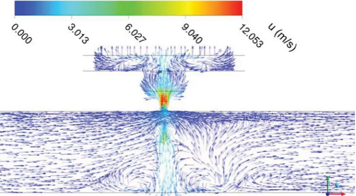
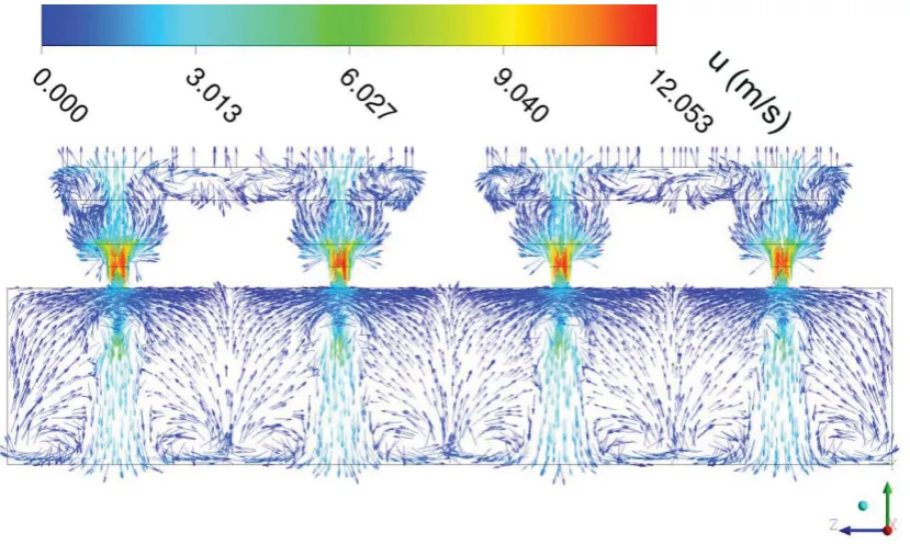
A numerical part of this study has started by validation and verification of the method. This step confirmed the present approach, as was discussed somewhere else [15, 16]. Figures 3 and 4 show the velocity vectors at Plane II and III at the instant of the beginning of the 10th period. Evidently, the flowfield is very complex, and several significantly different areas can be distinguished, such as the unaffected channel flow, areas of the jet impingement and their subsequent interactions. From the point of view of the wall heat transfer, a very interesting are mainly tree particular flowfield structures, which are clearly indicated in Figs. 3 and 4. First and second ones are shown in Fig. 3, revealing an interesting (in fact expected) non-symmetry of the flowfield:
x The windward side of SJ exhibits rather large vortex structure near the exposed wall. Apparently, this vortex results from a mutual action of the impinging SJ and separated channel flow. The former effect is known as the unsteady separation even at steady impinging jets, and oscillating features of SJs promote this effect. The latter effect is known as the horseshoe vortex upstream an obstacle or a jet in a cross flow.
x The leeward side of SJ exhibits very large structure resulting from a flow separation upon the exposed wall and from the wake flow downstream the SJs.
x The third flowfield structure is shown in Fig 4 – it is located between the SJs in Plane I. It is the reverse stagnation line known from the wall jets running in opposite directions.
Obviously, all these structures can contribute a desirable heat transfer enhancement. More precisely, they can promote a spreading of the heat transfer enhancement region over a larger area (the maximum of the heat transfer rate will be always in the stagnation point of the impinging SJ).
Figure 5 shows the local heat/mass transfer distribution along the channel wall without SJs. The comparison of the results obtaining with fine and coarse meshes confirm reliability of the computation and mesh independency for a developed channel flow, because nearly no differences between both results are found for x/H>–5. On the other hand, differences exist in the part of the channel flow development, x/H<–5. Figure 5 shows a comparison of the numerical and experimental [17] results. A rather reasonable agreement can be concluded.
experimental data. Moreover, the numerical results show surprisingly small heat transfer enhancement area. Reasons for these disagreements are still unknown. They can result from principal differences of the thermal conditions (despite the effort to define them as similar as possible – taking into account the heat and mass transfer analogy). These effects will be investigated in the near future.
4. CONCLUSION
A transient simulation of synthetic jets operating across the laminar channel flow has been performed. The numerical solution has been verified to ensure the solution is physically meaningful and validated with experimental data with fair agreement as well as a mesh convergence to demonstrate grid independence.
Reasonable results of are achieved in numerical simulation of unsteady flow fields. The results show interesting flow structures, which agree with expectations, and which can be useful for heat transfer enhancement.
The results in numerical simulation of heat transfer demonstrate enhancement of the heat transfer rates in comparison with the steady state. It agrees with the experiment. On the other hand, numerical simulation still over predicts this enhancement effect. An explanation of this difference will be matter for the near future.
5. A
CKNOWLEDGEMENTWe gratefully acknowledge the support of GA AS CR (IAA 200760801), and GA CR (P101/11/J019)
6. R
EFERENCES[1] Shah R.K., London A.L., Laminar Flow Forced Convection in Ducts: A Source Book for Compact Heat Exchanger Analytical Data, Adv. Heat Transfer, Supplement I, Academic, New York, 1978.
[2] Jiji L.M., Heat Convection, Springer-Verlag, Berlin Heidelberg, 2006.
[3] Mokrani O., Bourouga B., Castelain C., Peerhossaini H., Fluid Flow and Convective Heat Transfer in Flat Microchannels. Int. J. Heat Mass Transfer 52 (5–6) (2009) 1337-1352.
[4] Smith B.L., Glezer A., The formation and evolution of synthetic jets, Phys. Fluids 10 (1998) 2281–2297.
[5] Mallinson S.G., Reizes J.A., Hong G., An experimental and numerical study of synthetic jet flow, The Aeronautical Journal 105 (1043) (2001) 41–49.
[6] V., Zhong S., Efficiency of synthetic jets generation, Transactions of the Aeronautical and Astronautical Society of the Republic of China 35 (1) 2003 45– 53.
[7] G G G >? > # -zero-net-mass-flux jet, Phys. Fluids 18 (8) (2006) 081701-1–081701-4.
[8] Kercher D.S., Lee J-B., Brand O., Allen M.G., Glezer A., Microjet cooling devices for thermal management of electronics, IEEE Tranaction on Components and Packaging Technologies 26 (2) (2003) 359–366.
[9] G G " > =// ";
[10] Timchenko, V., Reizes, J. A, Leonardi, E., An Evaluation of Synthetic Jets for Heat Transfer Enhancement in Air Cooled Micro-Channels, Int. J. Numer. Methods Heat Fluid Flow, 17(3) (2007) 263-283.
[11] Timchenko, V., Reizes, .I. A., Leonardi, E., Stella, F., Synthetic Jet Forced Convection Heat Transfer Enhancement in Micro-Channels, Proceedings of the 13th International Heat Transfer Conference IHTC-13, Sydney, NSW, Australia, Aug. 13-18, 2006.
[12] Lee A., Timchenko V., Yeoh G.H., Reizes J.A., Three-dimensional modelling of fluid flow and heat transfer in micro-channels with synthetic jet. Int. J. Heat Mass Transfer (2011) article in press.
[13] G G/-B., Enhancement of synthetic jets by means of an integrated valve-less pump, Part II: Numerical and Experimental Studies, Sensors and Actuators A 125 (1) (2005) 50–58.
[14] G / !G G = G G " "; controlled by synthetic jet array. In: Proceedings of the 6th International Symposium on Turbulence, Heat and Mass Transfer (THMT’09), Rome, Italy, Sept. 14–18, 2009. Editors: K. Hanjalic, Y. Nagano, S. Jakirlic; Begell House Inc., New York, Wallingford (UK), pp. 935–938, (No. E-0090).
[15] Lam J.H., Numerical study of heat transfer enhancement in low Reynolds number channel flow with synthetic jets. Bc.-Thesis, UNSW, Sydney, 2011.
[16] Timchenko V., Numerical and Experimental Studies of Low Reynolds Number Synthetic Jets. Invited lecture at the Institute of Thermomechanics, Prague. Oct. 26, 2011.
[17] GGG G"G caused by a laminar channel flow equipped with a synthetic jet array. Trans. ASME, Journal of Thermal Science and Engineering Applications 2 (4) (2010) 041006-1 – 041006-8.
Fig. 1 Schematic of the present configuration: (a) experimental model - detail of the SJ actuators, (b) domain for computations.
Fig. 2 Visualization of four SJs in quiescent water at Plane III, without channel flow.
Fig. 4 Velocity vectors at Plane III at the instant of the beginning of the 10th period.
Fig. 5 Local heat/mass transfer distribution along the channel wall without SJs.