134 | P a g e
DESIGN AND IMPLEMENTATION OF WCDMA RAKE
RECEIVER USED IN 3G WIRELESS
COMMUNICATION
Kapil Sahu
1,
Sarita Boolchandani
2, Brijesh Kumar
31,2,3
E & C Dept., Vivekananda Institute of Technology-East, (India)
ABSTRACT
In this paper, we describe the design and implementation of WCDMA Rake receiver using VHDL. 3G generation
mobile communication is advanced and emerging technology in the field of wireless communication. Third
generation Communication has advanced facilities like multimedia accessing, internet service and higher capacity
of data rates [1]. The Rake receiver involves descrambling, dispreading, channel estimation and fading cancellation
[2]. The main principle behind Rake receiver is that they exploit multipath propagation by receiving the multipath
components of the transmitted signal separately and combining their energies. The Rake receiver is used to tackle
the problems of time dispersion (echoes) caused by multipath propagation in mobile communication [3]. RAKE
receiver consists of four fingers and all the energies of four fingers are combined in a single block. Which is time
delayed version of original signal and combining is done in such a way to improve signal to noise ratio and reduces
the multipath delay [1]. The above paper solves the above mention problems we have proposed architecture of
WCDMA Rake receiver which is implemented in VHDL. The synthesis done by Xillling and simulation is done by
modelSim6.3f.
Keyword: 3G, Fading Cancellation, Multipath Fading, Scrambling, Spreading, WCDMA.
I INTRODUCTION
The W-CDMA is a Wideband Direct Sequence Code Division Multiple Access (DS-CDMA)system. This system
provides very high bit rate (up to 2 Mbps) the use of variable spreading factor and multicode connections are
supported. User information bits are spread over wide bandwidth by multiplying the user data with quasi-random
bits (called chips) derived from CDMA spreading code. The chip rate of 3.84 Mcps and each channel bandwidth is
approximately 5 MHz [1]. Compared to GPRS (171.0kbits/sec) ,IS95B(115.2kbits/sec),CDMA2000(614.2kbits/sec)
and EDGE (473.0kbits/sec), WCDMA supports high user data rates(2072.0Kbps) and also has certain performance
benefits such as increased multipath diversity.[4] The WCDMA supports highly variable user data rates (called
Bandwidth on Demand) [1]. WCDMA supports Frequency Division Duplex (FDD) and Time Division Duplex
(TDD). In FDD mode separate 5 MHz carrier frequencies are used for uplink and downlink respectively. WCDMA
employs coherent detection on uplink and downlink based on the use of pilot symbols or common pilot. The
International Journal of Advance Research In Science And Engineering http://www.ijarse.com
IJARSE, Vol. No.3, Issue No.11, November 2014 ISSN-2319-8354(E)
135 | P a g e
detection and smart adaptive antennas, can be deployed by the network operator as a system option to increase
capacity and/or coverage. This facility is not provided in second generation communication system. [5]
Third Generation is advanced technology in the field of communication, supports multiple services like voice
transmission, sending messages through email, fax, medium and high rate multimedia like internet access and file
transfer respectively. This third generation uses the technology called Code Division Multiple Access
(CDMA).CDMA is used because of higher capacity, improved performance in multipath diversity and capable of
handling high peak data rates (2Mbps). WCDMA is the enhanced technology of CDMA. In WCDMA in which for
fading cancellation RAKE receiver is used.
The main principle of RAKE receiver is that they exploit multipath propagation by receiving the multipath
components of the transmitted signal separately and combining their energies [3]. The complete design, for this
purpose, can be segmented into distinct stages or blocks based on their functionality. The incoming data is fed to
different fingers after different delays. In each finger the data is descrambled and then despreaded through a
matched filter. For descrambling, a Gold code generator also has been implemented, which can be initialized by
external controls. For despreading the OVSF code sequence is taken as input to the chip. From matched filter
outputs we separate the information and pilot symbols. The pilot symbols are used to estimate the channel. After the
channel characteristics are estimated finally the outputs of all the fingers are combined together through a fading
cancellation block. Rake receiver handles QPSK and processes the in-phase and quadrature components of the data.
[4] The main objective of using a RAKE receiver is to combine the energies of all the multipath signals that reach
the receiver within a reasonable time window. The RAKE receiver is used to tackle the problems of time dispersion
(echoes) caused by multipath propagation in mobile communication [3].
II DESCRIPTION OF THE PROBLEM
A RAKE receiver is used to tackle the problems of time dispersion (echoes) caused by multipath propagation in
mobile communications, where we most often don‟t have any line-of-sight between the transmitter and the receiver.
Instead the signal reaches the receiver through a number of different paths, undergoing different and varying
amounts of delay and attenuation [3]. This phenomenon is termed as fading and is observed as rapid fluctuations of
the amplitude of a radio signal over a short period of time or travel distance. Fading is caused by interference
between two or more versions of the transmitted signal, which arrive at the receiver at slightly different times. The
physical factors influencing fading are [6]
Multipath Propagation
Speed of mobile
Speed of surrounding objects
136 | P a g e
Fig. 1: Multipath propagation in mobile communications [3]
III PROPOSED SOLUTION
Overview
of the Design,
The main principle of Rake receivers is that they exploit multipath propagation byreceiving the multipath components of the transmitted signal separately and combining their energies. The complete
design, for this purpose, can be segmented into distinct stages or blocks based on their functionality. The incoming
data is fed to different fingers after different delays.
OUTPUT
.
Fig. 2: Block diagram of rake receiver
QPSK i/p
International Journal of Advance Research In Science And Engineering http://www.ijarse.com
IJARSE, Vol. No.3, Issue No.11, November 2014 ISSN-2319-8354(E)
137 | P a g e
In each finger the data is descrambled and then despreaded through a matched filter. For descrambling, a Gold code
generator has also been implemented, which can be initialized by external controls. For despreading the OVSF code
sequence is taken as an input to the chip. From matched filter outputs and channel estimation outputs, we separate
the information and pilot symbols. The pilot symbols are used to estimate the channel. After the channel
characteristics are estimated, finally, the outputs of all the fingers are combined together through a fading
cancellation block. It should be noted that the design handles QPSK data and hence contains two parallel blocks,
which interact with each other only in the „Descrambler‟ & „Fading Cancellation‟ blocks, to process the in-phase
and quadrature components of the data. The backbone of RAKE receiver is shown in Fig. 2.
IV FUNCTIONAL BLOCKS DESCRIPTION
The above diagram shows the major functional blocks of the design. The functions of all these blocks are described
here. Register block are designed using two flip-flops – „toggle‟ and „follow‟ and configure them to realize
edge-triggered-reset registers. Register are designed on the basis of asynchronous reset with synchronous output. This
reduces the delay time rather than asynchronous reset with asynchronous output. The chip delay is used to introduce
one chip period. This is implemented using a register. [5] Descrambler multiplies the incoming QPSK data by a
complex code sequence, which is the complex conjugate of a Gold code sequence at transmitter end. Gold code
Generator block generates the Gold code whose complex conjugate is used as the „Descrambling code‟ [10] .
Matched Filter block performs the function of despreading the incoming data, by multiplying it by the same OVSF
code that is used at the transmitter to spread the information symbols, and accumulating the result over each
information symbol period. Channel estimation block finds the characteristics of the channel by processing the
received values of the „Pilot symbols‟ whose original sequence is known, in advance, at the receiver. The channel is
estimated once every slot of data. Fading Cancellation block is used to neutralize the channel effects and combine
the signal in each of the fingers so as to increase SNR. This is done by multiplying the outputs of each finger by the
complex conjugates of the corresponding channel characteristics and then adding their results. So we have to
perform four complex multiplications for each information symbol. However, for this purpose, we have used a
single multiplier.
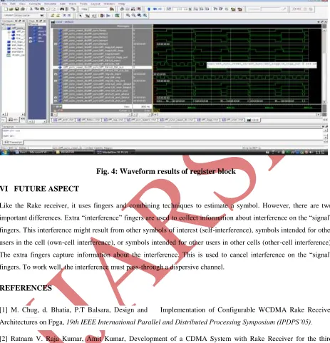
V IMPLEMENTED RESULT USING VHDL
138 | P a g e
Fig. 4: Waveform results of register block
VI FUTURE ASPECT
Like the Rake receiver, it uses fingers and combining techniques to estimate a symbol. However, there are two
important differences. Extra “interference” fingers are used to collect information about interference on the “signal”
fingers. This interference might result from other symbols of interest (self-interference), symbols intended for other
users in the cell (own-cell interference), or symbols intended for other users in other cells (other-cell interference).
The extra fingers capture information about the interference. This is used to cancel interference on the “signal”
fingers. To work well, the interference must pass-through a dispersive channel.
REFERENCES
[1] M. Chug, d. Bhatia, P.T Balsara, Design and Implementation of Configurable WCDMA Rake Receiver
Architectures on Fpga, 19th IEEE International Parallel and Distributed Processing Symposium (IPDPS’05).
[2] Ratnam V. Raja Kumar, Amit Kumar, Development of a CDMA System with Rake Receiver for the third
generation Wireless Communication System, 2002 IEEE (ICPWC’2002).
[3] Tommy Heikkila, RAKE RECEIVER, S72.333 Postgraduate Course in radio Communication, autumn 2004.
[4] L. Harju, M. Kuulusa, and J. Nurmi, A Flexible RAKE Receiver Architecture for WCDMA Mobile Terminals,
IEEE Third Workshop on Signal Processing Advances in Wireless Communications.
[5] Nikhil B. Patel1 and K. R. Parmar2, SNR Performance Analysis of Rake Receiver for WCDMA, International
Journal of Computational Engineering & Management, Vol. 15 Issue 2, March 2012.
[6] Rappaport, Wireless Communications Principles and Practice, Prentice Hall, New Jersey, 1996, pp.
International Journal of Advance Research In Science And Engineering http://www.ijarse.com
IJARSE, Vol. No.3, Issue No.11, November 2014 ISSN-2319-8354(E)
139 | P a g e
[7] B. P. LATHI, Modern Analog & Digital Communication System, Third generation OXFORD University Press,
NEW YORK, 1998, Pg. 605-608.
[8] Douglas Perry, Programming By Example, Tata MC Graw fourth edition, 2002.
[9] J .Bhaskar, “A Vhdl Primer”, PEARSON Education, Third Edition 2008
![Fig. 1: Multipath propagation in mobile communications [3]](https://thumb-us.123doks.com/thumbv2/123dok_us/7756338.1272166/3.612.54.539.78.730/fig-multipath-propagation-mobile-communications.webp)