149 | P a g e
GSM BASED LED DOT-MATRIX MESSAGE DISPLAY
Vishvendra Pal Singh Nagar
Department of Computer Science & Engineering, Satya College of Engineering & Technology,
Palwal, Haryana, (India)
ABSTRACT
The information sharing aspect of Information Technology is playing a prominent role in all kind of business
either it’s a NPO or Profit organization. All kind of business requires and adopts the facility of advertisement to
promote their services and products. Information technology makes the advertisement methods more technical
and effective as it is easy to transmit and share information. Digital Advertisement is the current requirement of
the modern business & Information world. Scrolling LED dot-matrix display boards are used at International
Airports, Stock Exchanges, Metro rail stations, shopping complex etc., LED display is an effective mode of
displaying information but the complicated task is to make the messages dynamic as the user have to change the
message content according to the specific requirements. In case of changing the message content the user have
to connect the LED board with the computer, so that the display board cannot be placed anywhere because of
dedicated & complex wiring pattern.
GSM based LED dot-matrix display makes the wireless connection between user mobile and LED display. It
provides the facility of real-time message displaying means user can change the message content that is to be
display according to his/her will. A mobile is used to send the message to the GSM based LED display and the
microcontroller does all processing of displaying the message content on the LED display in scrolling pattern.
The aim of the project is to develop a wireless scrolling message board that facilitate the user to change the
message content without connecting the Display board with the computer or laptop. The user can update the
message content from the remote location. The flash memory of the SIM is cleared after reading the update
message to make space available for next message.
I. INTRODUCTION
This project is based on the idea of designing a system for wireless communication between mobile phone and
LED display board. With the combination of GSM modem controlled by microcontroller using AT command
set for an effective wireless communication system function. It provides the certain level of accuracy [1].
The user having GSM mobile handset can send message to the display board to flash or to display message
content in scrolling pattern. GSM modem is used to receive the message at the receiver circuit. The message
content sent by the user is stored into the SIM attached to the GSM modem. AT commands are used to
communicate with the GSM modem by the microcontroller, AT is the abbreviation of Attention [2].
For the hardware simplification and current required for the module, the Multiplexing of LED is implemented
according to the requirement, as only 30 LED’s are glowing at one time resulting in reduction of power supply
150 | P a g e
The led dot-matrix display board accommodates 6x8 led with a distance between the rows of pins of 10mm. Apreprogrammed microcontroller is user to supply with the standard format of character set containing character
& alphabets with the possibility of generating and displaying punctuation marks, numbers, and special
characters, simple graphics. Each character is display in the pattern based on HEX values that are stored in the
microcontroller that is termed as look up or match table. The microcontroller looks or matches from pattern and
sends out the data bits serially and clock signal. Shift register is used to shift data between the pins connected to
each LED. Persistence of vision is the base of the fast scanning of data that is sent on rows and column, which
allows the pattern to be displayed because of persistence of vision. Decade counter is used to control the rows
on the bases of pulses that is connected to the clock input of the microcontroller [3].
This wireless system of communication requires the following hardware and components
• GSM modem-simcom(SIM900)
• Microcontroller- ATMEL-ATmega328p.
• 6X24 LED dot matrix .
• 74HC595 shift register.
• 4017 decade counter.
• Current limiting Resistors- 220 ohm, 560ohm, 1kohm
• Crystal 16.00 mhz.
• 2N3904 transistors • Max232 circuit
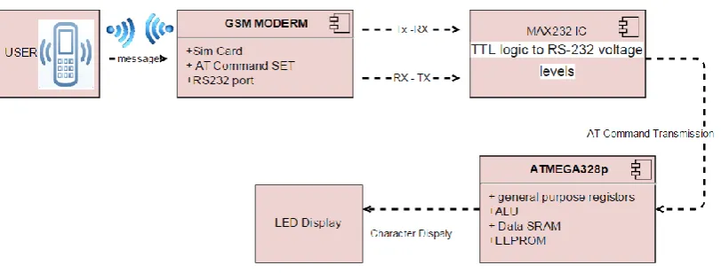
II. BLOCK DIAGRAM OF SYSTEM
Figure 1: Block Diagram of System
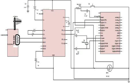
III. CIRCUIT DIAGRAM
There are three interfacing circuit:
a) Microcontroller interfacing MAX-232 TTL convertor for interfacing with GSM modem(fig 3)
b) Microcontroller interfacing with decade counter and shift-registers(fig 4)
151 | P a g e
IV. HARDWARE PROFILE
4.1 GSM Modem Sim900
GSM modem is used to communicate between user and the display board, it consist of slots for holding SIM
card and RS-232 port for connection with computer and other devices, works on frequencies 850/ 900/ 1800/
1900 MHz. The baud rate is configurable from 9600-115200 through AT command, It is suitable for SMS,
Voice as well as DATA transfer application in M2M interface, and used for sending SMS and receiving SMS by
controlling it through AT command set from microcontroller and computer[4].
Modem Features:
• Quad-Band GSM/GPRS 850/ 900/ 1800/ 1900 MHz • RS232 interface for direct communication
• Configurable baud rate • SIM Card holder.
• Built in Network Status LED
• Inbuilt Powerful TCP/IP protocol stack for internet data transfer over GPRS. • SMS
1. Point to point MO and MT
2. SMS cell broadcast
3. Text and PDU mode
• Input Voltage: 5V-12V DC
4.2 Max-232 TTL Convertor
MAX-232 deriver provides RS-232 voltage level output used for communication between various electronic
devices. It has two drivers that coverts TTL logic to RS-232 voltage level and two receivers that converts form
RS-232 to TTL voltage levels during the communication for RX and TX requirements between the devices. The
signals can be converted in each direction. It receives TTL level to covert then it changes a TTL logic 0 to
between +3 and + 15V and change TTL logic 1 to between -3 to -15V for converting from RS232 to TTL [4].
4.3 Atmga328p Microcontroller
In this current project the ATMEL 8-BIT MICROCONTROLLER is used to control all input output peripherals of LED
Display and GSM Modem. It creates the interface between GSM modem and LED Dot matrix display. It is 8-bit AVR
RISC-based microcontroller combines 32KB ISP flash memory with read-while-write capabilities, 1KB EEPROM, 2KB
SRAM, 23 general purpose I/O lines, 32 general purpose working registers, three flexible timer/counters with compare
modes, internal and external interrupts,serial programmable USART, a byte-oriented 2-wire serial interface, SPI serial port,
6-channel 10-bit A/D converter (8-channels in TQFP and QFN/MLF packages), programmable watchdog timer with internal
oscillator, and five software selectable power saving modes. The device operates between 1.8-5.5 volts [5].
Atmga328p Features
High Performance, Low Power Atmel®AVR® 8-Bit Microcontroller Family
High Endurance Non-volatile Memory Segments
Advanced RISC Architecture
1. 131 Powerful Instructions – Most Single Clock Cycle Execution
152 | P a g e
3. Fully Static Operation4. Up to 20 MIPS Throughput at 20MHz
5. On-chip 2-cycle Multiplier
Operating Voltage: n1.8 - 5.5V
Temperature Range:-40C to 85C
AT commands will transmitted by the microcontroller for receiving SMS from GSM modem and provides with
the data signal and clock signal for scrolling the message.
4.4 6X24 LED Dot Matrix Display
LED Matrix is based on dot matrix pattern that are two-dimensional patterned array that are used to represent
characters, symbols and images. It consists of two-dimension matrix where cathodes and anodes are joined
together respectively representing the rows and column. The information is flashed on the display by controlling
and directing the flow of electricity through columns and rows. A 6 row and 24 column led matrix requires 144
leds all are connected together with common anodes and common cathodes . In this pattern all 144 led are
connected to form a matrix of 6*24, all anodes are representing the columns and all cathodes are representing
rows. With the combination of row and column each individual LED can be controlled by multiplexing [6].
4.5 Shift Register
Shift registers are a type of sequential logic circuit, mainly for storage of digital data. They are a group of
flip-flops connected in a chain so that the output from one flip-flop becomes the input of the next flip-flop. Most of
the registers possess no characteristic internal sequence of states. All the flip-flops are driven by a common
clock, and all are set or reset simultaneously
In this project 74HC595 shift register are user to control the flow of current in the column of the display. It has
an 8 bit storage register and an 8 bit shift register. Data is written to the shift register serially, then latched onto
the storage register. The storage register then controls 8 output lines [7].
4.6 Decade Counter
Decade counter stores the stage that has count ten states; it can count through decade or 10 states per stage.
Rather than binary code decimal, decade counter counts in decimal digits, decade counter is also a binary
counter designed to count decimal 10(1010b). Decade counter counts from 0 to 9 and resets to zero. To set the
counter output zero needs to pulse reset line low, then each clock pulse increment is counted until it reaches
decimal 9 or 1001. Both NANAD gate inputs are high when there is an increment to decimal 10 or to 1010.
After the increment to decimal 10 NAND output goes low, and counter resets to zero. 4017 is 5 stage decade
counter (one stage consist of ten state count), with 10 decoded outputs Q0 to Q9, Q5 to Q9 are most significant
flip-flop output provider, CP0 and CP1 are two clock inputs and MR is an overriding master reset input [8].
4.7 Crystal 16.00 Mhz Oscillator
It works on the mechanism of piezoelectric material to create an electrical signal with a very precise frequency.
This frequency is commonly used to keep track of time. Crystal is used
In order to have a baud rate of 9600 for serial communication with modem. Also a higher value of crystal
153 | P a g e
V. WORKING PROCEDURE
The user will send message that will be received by the GMS modem, and the GSM modem communicate with
microcontroller using serial communication port RS232 with baud rate 9600. Microcontroller transmits AT
commands to read the message from the GSM modem SIM.
• AT ……{ to initialize the modem} • ATE0………{to turn echo off}
• AT+CMGF=1….{to set the message format to TEXT} • AT+CNMI=2,1,0,0,0...{notification of new message} • AT+CMGR=1…….{to read the stored message} • AT+CMGD=1……{to delete the message}
First three commands, GSM modem responds to the microcontroller with the message ’OK’. This message is
ignored by the microcontroller. After the execution of the final AT command, the GSM modem responds with
the following long message.
+CMGR:”REC UNREAD”,” sender’s number”,”Date and time”
Message part here
OK
The microcontroller only keeps the message part and discards the remaining message. This message is stored in
the buffer array which is later used to display the message on the dot matrix led module.6. Message Display on
LED Matrix process
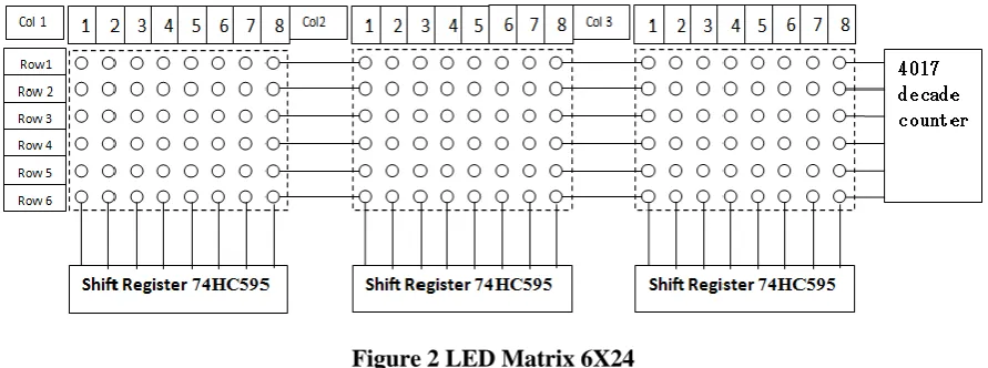
Figure 2 LED Matrix 6X24
According to the figure 1 three shift registers are used (one shift register for each 6X8 block of LED set) for the
input signal of LED column and a decade counter is used for the row input signal control. The six display matrix
row using the output of the atmega328p, that is controlling 4017 decade counter as well as 74HC595 shift
register for column. A current limiting register is connected with each LED of the column. The shift register
can resist current up to 8mA. The binary code of 0 and 1 is used for blinking the LEDs in the sequence to
display character. Microcontroller use the ASCII code of the character to be display stored in the internal
memory that matches the pattern in character generation. Controller send the series of display pattern to the shift
register. Any bit pattern that is ‘1’ means turn on the LED, and any bit pattern that is ‘0’ means off LED. The
154 | P a g e
other 2 matrix display column segment now decade counter first pin control the first row of the matrix. All highLED display the character pattern. This process is repeated for all rows and columns.
Following is the pattern for display character on LED matrix
BA {B01110000,B10001000,B10001000,B11111000,B10001000,B10001000}
BB {B11110000,B10001000,B10001000,B11110000,B10001000,B11111000}
BC {B11111000,B10000000,B10000000,B10000000,B10000000,B11111000}
BD {B11110000,B10001000,B10001000,B10001000,B10001000,B11110000} etc.
The 16 bit display buffers are used for scrolling effect in 3 display matrix and the message sceoll from right to
left direction.
VI. CONCLUSION
GSM plays vital role in wireless technology, this project describes how a person can develop a LED matrix that
can display scrolling message with support of GSM modem and other specified hardware. The multiplexing
technique is used for displaying character on the matrix and the scrolling speed can be controlled by the
microcontroller. This project can be used anywhere as it is based on wireless communication. Its dynamic
messaging display nature makes it feasible for use in every field where the content keeps of changing like stock
exchange, railways, airports, restaurants etc. the major advantage of this project is advertising as the display
board can be placed at any height either in air or on earth there is no requirement of wires to communicate.
155 | P a g e
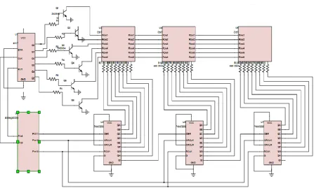
Figure 4 Microcontroller Interfacing with Decade Counter and Shift-Registers
156 | P a g e
REFERENCES
[1]. SMS BASED WIRELESS NOTICE BOARD DISPLAY USING GSM MOBILE: Payal Mishra1 , Pinki
Singh, Shivani Gupta IJARSE, Vol. No.2, Issue No.10, October 2013 ISSN-2319-8354(E)
[2]. Mrs. S.P.Gaikwad , Manikeshwari Shahdeo , Meghna Priya , Prashant Kr. Raghav, Wireless GSM Based
Electronic Notice Board.
[3]. The 8051 Microcontroller And Embedded Systems Using Assembly And C by Janice Gillispie Mazidi,
Rolin D. McKinlay, Muhammad Ali Mazidi.
[4]. probots.co.in/Manuals/SIM900.pdf
[5]. http://www.nxp.com for 4017 decade counter.
[6]. Atmel-8271I-AVR- ATmega-Datasheet_10/2014 www.atmel.com
[7]. www.nxp.com/documents/data_sheet/74HC_HCT595.pdf