Assessing through-thickness damage propagation, impact tests on layered
composite beams - experimental work and numerical simulation
IgnacioVidal-Pérez1,∗,RasmusEriksen1,ChristianBerggreen1,andJørgenKepler2
1DepartmentofMechanicalEngineering,TechnicalUniversityofDenmark,NilsKoppelsAllé,2800KongensLyngby,Denmark 2DepartmentofMaterialsandProduction,AalborgUniversity,Fibigerstraede14,9220Aalborg,Denmark
Abstract.The growing applications of layered fiber reinforced composite materials lead to the potential use of such lightweight materials for blast and ballistic impact resistant panels. Under such high strain rate load-ing, through-thickness damage propagation is crucial for the structural integrity of the panels. Experiments performed in composite panels under blast loading exhibited little information for the understanding of the time-line of damage propagation as only post-mortem inspection can be done. Instrumentation may be installed in order to follow the blast but the task reveals itself arduous as all the instruments must be protected against the blast. The sparse information can be valuable for configuration screening purposes, but is not sufficient for comparison and validation of numerical models. The work focuses on performing controlled impact experi-ments in narrow beams filmed side-wise with high-speed cameras. The narrow geometry of the beams leaves the thickness of the specimen exposed to the cameras allowing for a real-time monitoring of the stress waves propagating and for assessing the time-line of through-thickness damage propagation onset. Results showed that polyethylene impactors, given the right diameter, are the most suitable soft impactors. Numerical models including in-plane and out-of-plane damage propagation are being built in order to replicate the experimentally observed damage. The ultimate goal being establishing design rules for such lightweight fiber reinforced pan-els. It is numerically observed that, the speed propagation of delamination in the longitudinal direction reaches a common constant value for all interfaces.
1 Introduction
Full-scale Glass Fiber Reinforced Plastic (GFRP) plates have been tested under blast loading for several con-figurations of composites, steels, and mixed structures. Although the full-scale tests contributed to direct the re-search towards the most resistant configurations, little in-formation could be extracted of the very short time when the transient failure phenomenon developed. Only post-mortem inspection could be performed, which led to the need of designing a new experimental setup allowing for this transient failure time-line to be observed and repli-cated via numerical simulations. This paper aims to de-scribe the experimental setup, including the trials that led to its final design, describe the first tests performed with it, and finally outline the numerical model built for replicat-ing the experimental results.
2 Experimental Setup
2.1 DescriptionExperiments are being conducted at the impact laboratory facilities of the Department of Materials and Production in Aalborg University, Denmark. The setup consists of a target frame and a gas gun as shown in figure 1.
∗e-mail: [email protected]
a)
b)
Fig. 1.AAU Impact laboratory facilities: a) AAU impact
labora-tory, target Frame, b) Gas gun, AAU impact laboratory.
A∅20 mm, 2 m long, barrel has been used, reaching maximum velocities of approx. 500m/s. The gas gun pro-pels the projectiles using air at a maximum of 200 atm., released by a manual valve.
so-licited out of plane. This is done by means of high-speed cameras filming the specimen side-wise, leaving the en-tire side of the plate visible to the cameras, as opposed to traditional plate geometries.
2.2 Beam specimens
Selected beam specimens with different GFRP laminate configurations have been tested along with layered steel/GFRP configurations.
The beam dimensions are 320 mm x 20 mm x th,
th being the beam thickness, which is dependent on each particular beam configuration as all the beams are designed to have an equal area weight of 44kg/m2.
It has been found that painting the observed side of beam specimens matte withe enhances the damage observation. 5 mm apart black lines have been painted on the impactor and the specimens in order to have a sense of scale while analyzing the recordings. See figure 2.
(a)
(b)
Fig. 2. Beam specimens before impact. a) Before painting, b)
After painting.
2.3 Impactor considerations
Several impactors, 50 mm long cylinders with a 20 mm di-ameter have been tested in order to assess their suitability. Several disturbing phenomena were identified and trials were made in order to avoid them. The main goals being ensuring repeatability, minimizing/suppressing initial impact flash and minimizing debris/impactor shattering that could blur or obstruct the camera view.
The following impactors: Nylon (PA6), Polyvinyl Chloride (PVC), Polyoxymethylene (POM), Polyethylene (PE) and Polyurethane-foam (PU) have been tested yielding different results in term of debris generation, impact flash and severity. Examples of these phenomena are reported in figure 3.
Figure 3a) shows a thickness spread mechanolumi-nescent flash upon initial contact. Figure 3b) shows a complete shattering of a PU impactor generating a considerable amount of debris that blur the view of
a)
b)
c)
d)
Fig. 3.Impactor surve: a) Nylon, b) PU-foam, c) PVC, d) PE.
the specimen. Figure 3c) shows also a PVC impactor shattering, however, the particles generated are less thin, which results in less disturbance for the image acquisition process. Figure 3d) shows a PE impactor experiencing a significant plastic deformation without shattering that gives way to a wrapping effect around the beam, possibly reducing the impulse transfered and certainly blocking the camera view of the first plies on the impact side.
2.4 Image acquisition
licited out of plane. This is done by means of high-speed cameras filming the specimen side-wise, leaving the en-tire side of the plate visible to the cameras, as opposed to traditional plate geometries.
2.2 Beam specimens
Selected beam specimens with different GFRP laminate configurations have been tested along with layered steel/GFRP configurations.
The beam dimensions are 320 mm x 20 mm x th,
th being the beam thickness, which is dependent on each particular beam configuration as all the beams are designed to have an equal area weight of 44kg/m2.
It has been found that painting the observed side of beam specimens matte withe enhances the damage observation. 5 mm apart black lines have been painted on the impactor and the specimens in order to have a sense of scale while analyzing the recordings. See figure 2.
(a)
(b)
Fig. 2. Beam specimens before impact. a) Before painting, b)
After painting.
2.3 Impactor considerations
Several impactors, 50 mm long cylinders with a 20 mm di-ameter have been tested in order to assess their suitability. Several disturbing phenomena were identified and trials were made in order to avoid them. The main goals being ensuring repeatability, minimizing/suppressing initial impact flash and minimizing debris/impactor shattering that could blur or obstruct the camera view.
The following impactors: Nylon (PA6), Polyvinyl Chloride (PVC), Polyoxymethylene (POM), Polyethylene (PE) and Polyurethane-foam (PU) have been tested yielding different results in term of debris generation, impact flash and severity. Examples of these phenomena are reported in figure 3.
Figure 3a) shows a thickness spread mechanolumi-nescent flash upon initial contact. Figure 3b) shows a complete shattering of a PU impactor generating a considerable amount of debris that blur the view of
a)
b)
c)
d)
Fig. 3.Impactor surve: a) Nylon, b) PU-foam, c) PVC, d) PE.
the specimen. Figure 3c) shows also a PVC impactor shattering, however, the particles generated are less thin, which results in less disturbance for the image acquisition process. Figure 3d) shows a PE impactor experiencing a significant plastic deformation without shattering that gives way to a wrapping effect around the beam, possibly reducing the impulse transfered and certainly blocking the camera view of the first plies on the impact side.
2.4 Image acquisition
A first acquisition was done using a Photron SA5 camera with up to 20.000 frames/second, yielding a time res-olution of 50 µs and an image resolution of 640 x 368 pixels. The purpose of the acquisition was to capture the
progression of the onset of delamination along the plies interfaces. The initiation of such delaminations is linked to the propagation of the pressure wave generated after impact throughout the thickness. The pressure wave speed is analytically calculated to be around 2.300 m/s. With an average specimen thickness of 25 mm, the wave pulse takes around 10µsto propagate thickness-wise, rendering the time resolution of the Photron SA5 camera not suitable. However, under the proper lighting conditions, the propagation of the delamination in the longitudinal direction can be assessed and recorded using this camera setup, see figure 4 below.
a) Frame1,t=0µs. b) Frame2,t=50µs.
c) Frame5,t=200µs.
Fig. 4. Delamination propagation, PU foam impactor, impact
velocity approx. 300 m/s.
It can be seen that, with a time resolution of 50 µs, it is not possible to capture the propagation of the onset of delamination thickness-wise between frame 1 and 2. However, the longitudinal progression is visible between frames 2 and 5.
In order to overcome the time resolution issue, a sec-ond setup was adopted using a Phantom V 2512 camera allowing for a frame rate up to 1.000.000 frames/second. In this particular case, 380.000 frames/s, i.e. a time resolu-tion of 2.6µsand an image resolution of 256 x 128 pixels were used. Therefore, the advance of the pressure wave traveling through the beam specimen thickness could be captured. It was then possible to evaluate the progression of through-thickness damage onset. See figure 5 below.
Frame 18 shows a delamination onset that has reached up to two thirds of the thickness whereas frame 39 shows that the delamination onset has reached the entire thick-ness of the beam.
a) Frame6,t=29µs. b) Frame18,t=87µs.
c) Frame39,t=189µs.
Fig. 5.Delamination propagation, PE impactor, impact velocity
approx. 500 m/s.
3 Numerical Model
3.1 DescriptionThe ultimate ambition of this study is to establish a numer-ical model capable of predicting the damage time-line of a beam subjected to high-strain rate loading such as blast loading and ballistic impacts.
A Finite Element model using the explicit solver LS-DYNA R9.01 has been built. Several material models were investigated by [1] for modeling composite under high strain rate loading. Ranging from isotropic linear elas-tic models up to orthotropic models including intralami-nar damage, strain rate effects and, potentially, interlami-nar damage modeling. MAT162 in LS-DYNA developed by the Center For Composites Material from the Univer-sity of Delaware, has been identified as the most suitable candidate for the numerical model. A more thorough de-scription of MAT162 model is stated in section 3.2.
In order to replicate the experiments described in sec-tion 2, a beam model has been built using MAT162.
3.2 Material Model
7 different modes of intralaminar damage, both for matrix and fibers, see [2].
MAT162 does not model delamination as topological separation of the layers. It does so by degrading the stiff-ness of the elements adjacent to the interfaces. In order to model topological separation of the layer, a step for-ward needs to be taken. The initial model has been built using TIEBREAK contacts between the layers. The differ-ent layers are not merged topologically but bound together by a contact modelisation that does not allow any relative movement between the layers as long as a quadratic fail-ure criteria taking into account Interlaminar Normal Stress and Interlaminar Shear Stress combined is achieved. The coulomb friction effect is also modeled between the in-terfaces, a compressive out-of-plane (OOP) stress will en-hance the Interlaminar Shear Strength (ILSS) before de-lamination.
3.3 Mesh convergence
Mesh convergence studies have been performed in order to establish the mesh refinement necessary to obtain sta-ble values in terms of displacement, in-plane stresses and OOP stresses.
0 1 2 3 4
Element Size [mm] 0
50 100
Max.
z
[MPa]
2nd Peak 3rd Peak 4th Peak 5th Peak
a) MaxσzStress Peaks with respect to element size.
0 1 2 3
Element Size [mm] 40
50 60 70 80
Max.
zx
[MPa]
1st Peak 2nd Peak 3rd Peak 4th Peak
b) MaxσzxStress Peaks with respect to element size.
0 2 4 6
Element Size [mm] -12
-10 -8 -6 -4
Max. Z displ. [mm]
c) Max Z displacement with respect to element size.
Fig. 6.Mesh convergence analysis.
It can be concluded that an average element size of 1mm is sufficient to ensure converged displacements, as well as converged dominant in-plane & out-plane stresses. This discretization corresponds to 300 elements length-wise, 18 widthwise, and 20 thickness-wise.
4 Results
The model allows delamination to propagate along the thickness and the longitudinal direction.
a)
b)
Fig. 7. Linear Orthotropic model : a)σzzatt=9µs. b)σzxat
t=20µs.
Comparison between the propagation of the delamination with respect to time will be done between the experimental recordings and the FE results.
7 different modes of intralaminar damage, both for matrix and fibers, see [2].
MAT162 does not model delamination as topological separation of the layers. It does so by degrading the stiff-ness of the elements adjacent to the interfaces. In order to model topological separation of the layer, a step for-ward needs to be taken. The initial model has been built using TIEBREAK contacts between the layers. The differ-ent layers are not merged topologically but bound together by a contact modelisation that does not allow any relative movement between the layers as long as a quadratic fail-ure criteria taking into account Interlaminar Normal Stress and Interlaminar Shear Stress combined is achieved. The coulomb friction effect is also modeled between the in-terfaces, a compressive out-of-plane (OOP) stress will en-hance the Interlaminar Shear Strength (ILSS) before de-lamination.
3.3 Mesh convergence
Mesh convergence studies have been performed in order to establish the mesh refinement necessary to obtain sta-ble values in terms of displacement, in-plane stresses and OOP stresses.
0 1 2 3 4
Element Size [mm] 0 50 100 Max. z [MPa] 2nd Peak 3rd Peak 4th Peak 5th Peak
a) MaxσzStress Peaks with respect to element size.
0 1 2 3
Element Size [mm] 40 50 60 70 80 Max. zx [MPa] 1st Peak 2nd Peak 3rd Peak 4th Peak
b) MaxσzxStress Peaks with respect to element size.
0 2 4 6
Element Size [mm] -12
-10 -8 -6 -4
Max. Z displ. [mm]
c) Max Z displacement with respect to element size.
Fig. 6.Mesh convergence analysis.
It can be concluded that an average element size of 1mm is sufficient to ensure converged displacements, as well as converged dominant in-plane & out-plane stresses. This discretization corresponds to 300 elements length-wise, 18 widthwise, and 20 thickness-wise.
4 Results
The model allows delamination to propagate along the thickness and the longitudinal direction.
a)
b)
Fig. 7. Linear Orthotropic model : a)σzzatt=9µs. b)σzxat
t=20µs.
Comparison between the propagation of the delamination with respect to time will be done between the experimental recordings and the FE results.
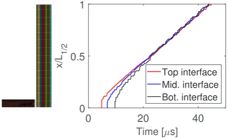
Figure 8 shows that delamination starts at the top interface and then propagates through thickness. It can be derived from the graph that, when the delamination
propagation speed stabilizes, it reaches a speed of around 3.800 m/s.
5 Ongoing work
The ongoing work focuses on integrating more sophisti-cated delamination models (i.e. Cohesive Zone Models), in order to replicate more accurately the experimental be-havior. Experiments are also carried in a continuous
man-ner in order to better understand the damage mechanisms of the different layered architectures.
References
1. Søren Giversen, Blast Testing and Modeling of Com-posite Structures,PhD Thesis. Technical University of Denmark (2014)
2. Bazle Z. (Gama) Haque, A progressive composite dam-age model for unidirectional and woven fabric compos-ites.MAT_162 LS-DYNA user manual(2015)
0 20 40
Time [ s] 0 0.5 1 x/L 1/2 Top interface Mid. interface Bot. interface
Fig. 8. Delamination propagation.x/L1/2: Delamination