STATCOM Device to Regulate PF of Grid Using Multi-Level Inverter
B Pavankumar
&
P. Sathyanarayana
[1]Assistant Professor, Department of EEE, Sreenidhi Institute of Science & Technology, Hyderabad, T.S, INDIA
[2]Assistant Professor, Department of EEE, Sreenidhi Institute of Science & Technology, Hyderabad, T.S, INDIA
Abstract-In this paper; the concept of a new multilevel inverter
with FACTS capability for small-to-mid-size wind installations is presented. The proposed system demonstrates the application of a new inverter with FACTS capability in a single unit without any additional cost. Replacing the traditional renewable energy inverters with the proposed inverter will eliminate the need of any external STATCOM devices to regulate the PF of the grid. The simulation results for an 11-level inverter are presented in MATLAB/Simulink. To validate the simulation results, a scaled prototype of the proposed 11-level inverter with D-STATCOM capability is built and tested. Practical results show good performance of the proposed control strategy even in severe conditions.
Keywords: D-STATCOM, FACTS, STATCOM.
1. INTRODUCTION
Energy for power grids, in terms of voltage and frequency. In permanent magnet (PM) wind applications, a back-to-back converter is normally utilized to connect the generator to the grid. A rectifier equipped with a maximum power point tracker (MPPT), converts the output power of the wind turbine to a dc power. The dc power is then converted to the desired ac power for power lines using an inverter and a transformer. With recent developments in wind energy, utilizing smarter wind energy inverters (WEIs) has become an important issue. There are a lot of single-phase lines in the United States, which power small farms or remote houses [1], [2]. Such customers have the potential to produce their required energy using a medium-size wind turbine. Increasing the number of small-to-medium wind turbines will make several troubles for local utilities such as harmonics or power factor (PF) issues. A high PF is generally desirable in a power system to decrease power losses and improve voltage regulation at the load. It is often desirable to adjust the PF of a system to near 1.0. When reactive elements supply or absorb reactive power near the load, the apparent power is reduced [3-6]. In other words, the current drawn by the load is reduced, which decreases the power losses. Therefore, the voltage regulation is improved if the reactive power compensation is performed near large loads. Traditionally, utilities have to use capacitor banks to compensate the PF issues, which will increase the total cost of the system. The modern ways of controlling the PF of these power lines is to use small distribution static synchronous compensators (D-STATCOMs). The D-STATCOMs are normally placed in parallel with the distributed generation systems as well as the power systems to operate as a source or sink of reactive power to
increase the power quality issues of the power lines. Using regular STATCOMs for small-to-medium size single-phase wind applications does not make economic sense and increase the cost of the system significantly [7, 8]. This is where the idea of using smarter WEIs with FACTS capabilities shows itself as a new idea to meet the targets of being cost-effective as well as compatible with IEEE standards. The proposed inverter in this paper is equipped with a D-STATCOM option to regulate the reactive power of the local distribution lines and can be placed between the wind turbine and the grid, same as a regular WEI without any additional cost. The function of the proposed
Fig 1: Complete configuration of the proposed inverter with FACTS capability
can provide STATCOM-like performances without the need for an external costly device.
2. Multi-Level VSI separate DC Source
A new multilevel voltage-source inverter with separate DC sources is proposed for high-voltage, high power applications, such as flexible AC transmission systems (FACTS) including static VAr generation (SVG), power line conditioning, series compensation, phase shifting, voltage balancing, fuel cell and photovoltaic utility systems interfacing, etc. The new M-level inverter consists of (M-1)/2 single phase full bridges in which each bridge has its own separate DC source. This inverter can generate almost sinusoidal waveform voltage with only one time switching per cycle as the number of levels increases. It can solve the problems of conventional transformer-based multi pulse inverters and the problems of the multilevel diode-clamped inverter and the multilevel living capacitor inverter. To demonstrate the superiority of the new inverter, a SVG system using the new inverter topology is discussed through analysis, simulation and experiment [11-15]. The D-STATCOMs are normally placed in parallel with the distributed generation systems as well as the power systems to operate as a source or sink of reactive power to increase the power quality issues of the power lines. Using regular STATCOMs for small-to-medium size single-phase wind applications does not make economic sense and increase the cost of the system significantly. This is where the idea of using smarter WEIs with FACTS capabilities shows itself as a new idea to meet the targets of being cost-effective as well as compatible with IEEE standards. The proposed inverter in this paper is equipped with a D-STATCOM option to regulate the reactive power of the local distribution lines and can be placed between the wind turbine and the grid, same as a regular WEI without any additional cost. The function of the proposed inverter is not only to convert dc power coming from dc link to a suitable ac power for the main grid, but also to fix the PF of the local grid at a target PF by injecting enough reactive power to the grid [16]. In the proposed control strategy, the concepts of the inverter and the D-STATCOM have been combined to make a new inverter, which possesses FACTS capability with no additional cost
3. DC-AC CONVERTER
DC to AC converters produces an AC output waveform from a DC source. Applications include adjustable speed drives (ASD), uninterruptable power supplies (UPS), active filters, (FACTS), voltage compensators, and photovoltaic generators. Topologies for these converters can be separated into two distinct categories: voltage source inverters and current source inverters. Voltage source inverters (VSIs) are named so because the independently controlled output is a voltage waveform. Similarly, current
source inverters (CSIs) are distinct in that the controlled AC output is a current waveform.
Being static power converters, the DC to AC power conversion is the result of power switching devices, which are commonly fully controllable semiconductor power switches. The output waveforms are therefore made up of discrete values, producing fast transitions rather than smooth ones. The ability to produce near sinusoidal waveforms around the fundamental frequency is dictated by the modulation technique controlling when, and for how long, the power valves are on and off. Common modulation techniques include the carrier-based technique, or pulse width modulation, space-vector technique, and the selective-harmonic technique.
Voltage source inverters have practical uses in both single-phase and three-phase applications. Single-phase VSIs utilize half-bridge and full-half-bridge configurations, and are widely used for power supplies, single-phase UPSs, and elaborate high-power topologies when used in multicell configurations. Three-phase VSIs are used in applications that require sinusoidal voltage waveforms, such as ASDs, UPSs, and some types of FACTS devices such as the They are also used in applications where arbitrary voltages are required as in the case of active filters and voltage compensators.
Current source inverters are used to produce an AC output current from a DC current supply. This type of inverter is practical for three-phase applications in which high-quality voltage waveforms are required.
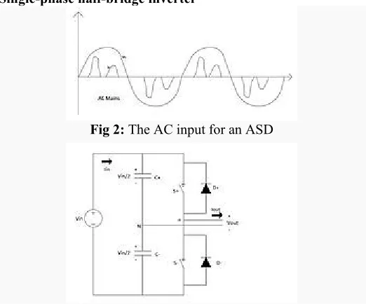
Single-phase half-bridge inverter
Fig 2: The AC input for an ASD
Fig 3: Single-Phase Half-Bridge Voltage Source Inverter
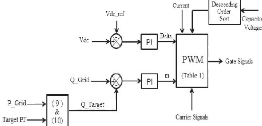
Fig 4: Control structure FACTS
Flexible AC Transmission Systems, called FACTS, got in the recent years a well known term for higher controllability in power systems by means of power electronic devices. Several FACTS-devices have been introduced for various applications worldwide. A number of new types of devices are in the stage of being introduced in practice.
In most of the applications the controllability is used to avoid cost intensive or landscape requiring extensions of power systems, for instance like upgrades or additions of substations and power lines. FACTS-devices provide a better adaptation to varying operational conditions and improve the usage of existing installations. The basic applications of FACTS-devices are:
Power flow control,
Increase of transmission capability, Voltage control,
Reactive power compensation, Stability improvement, Power quality improvement, Power conditioning, Flicker mitigation,
Interconnection of renewable and distributed generation and storages.
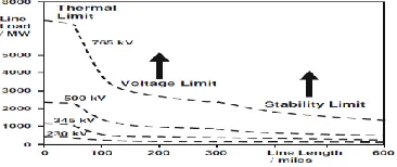
The usage of lines for active power transmission should be ideally up to the thermal limits. Voltage and stability limits shall be shifted with the means of the several different FACTS devices. It can be seen that with growing line length, the opportunity for FACTS devices gets more and more important. The influence of FACTS-devices is achieved through switched or controlled shunt compensation, series compensation or phase shift control. The devices work electrically as fast current, voltage or impedance controllers. The power electronic allows very short reaction times down to far below one second.
Fig 5: Operational limits of transmission lines for different voltage levels
The development of FACTS-devices has started with the growing capabilities of power electronic components. Devices for high power levels have been made available in converters for high and even highest voltage levels. The overall starting points are network elements influencing the reactive power or the impedance of a part of the power system. Fig 6 shows a number of basic devices separated into the conventional ones and the FACTS-devices
For the FACTS side the taxonomy in terms of 'dynamic' and 'static' needs some explanation. The term 'dynamic' is used to express the fast controllability of FACTS-devices provided by the power electronics. This is one of the main differentiation factors from the conventional devices. The term 'static' means that the devices have no moving parts like mechanical switches to perform the dynamic controllability. Therefore most of the FACTS-devices can equally be static and dynamic.
Fig 6: Overview of major FACTS-devices
The FACTS-devices contain these elements as well but use additional power electronic valves or converters to switch the elements in smaller steps or with switching patterns within a cycle of the alternating current. The left column of FACTS-devices uses Thyristor valves or converters. These valves or converters are well known since several years. They have low losses because of their low switching frequency of once a cycle in the converters or the usage of the Thyristors to simply bridge impedances in the valves.
4. STATIC SYNCHRONOUS COMPENSATOR (STATCOM)
The STATCOM is a solid-state-based power converter version of the SVC. Operating as a shunt-connected SVC, its capacitive or inductive output currents can be controlled independently from its terminal AC bus voltage. Because of the fast-switching characteristic of power converters, STATCOM provides much faster response as compared to the SVC. In addition, in the event of a rapid change in system voltage, the capacitor voltage does not change instantaneously; therefore, STATCOM effectively reacts for the desired responses. For example, if the system voltage drops for any reason, there is a tendency for STATCOM to inject capacitive power to support the dipped voltages. STATCOM is capable of high dynamic performance and its compensation does not depend on the common coupling voltage. Therefore, STATCOM is very effective during the power system disturbances.
Moreover, much research confirms several advantages of STATCOM. These advantages compared to other shunt compensators include:
Size, weight, and cost reduction.
Equality of lagging and leading output.
Precise and continuous reactive power control with fast response.
Possible active harmonic filter capability.
This chapter describes the structure, basic operating principle and characteristics of STATCOM. In addition, the concept of voltage source converters and the corresponding control techniques are illustrated.
Structure of Statcom
Basically, STATCOM is comprised of three main parts (as seen from Fig.1 below): a voltage source converter (VSC), a step-up coupling transformer, and a controller. In a very-high-voltage system, the leakage inductances of the step-up power transformers can function as coupling reactors. The main purpose of the coupling inductors is to filter out the current harmonic components that are generated mainly by the pulsating output voltage of the power converters.
Fig 7: Schematic of the proposed controller system. Simulink diagram of proposed system
The design of an 11-level MMC inverter was carried out in MATLAB/Simulink. The simulation is 20 s long
The goal is to assess the behavior of the control system in the worst conditions. Table II shows the values of the parameters used for the simulation. Before t = 6 s, there is no wind to power the wind turbine; therefore, the dc link is open-circuited. At t = 6 s, the input power of the inverter is ramped up to 12 kW in 5 s, and then ramped down to 3.5 kW 4 s later. Fig. 6 shows the output active power from the wind turbine. In the simulation, the local load makes the PF 0.82. When the simulation starts, the inverter provides enough compensation to reach the target PF 0.90. Fig. 7 shows the output active and reactive power from the wind turbine and the grid. After t = 6 s, the output power of the wind turbine is increased, and as a result the level of active power provided by the feeder line is decreased by the same amount. The simulated output voltage of the inverter before the filter is shown in Fig. 8. Fig. 9 shows the PF of the grid. The PF of the grid is constant at 0.90 regardless of the active power from the wind turbine, showing that the main goal of the inverter is achieved. The set-point for dc link voltage of the inverter is 2000 V and the RMS value of the output ac voltage is 600 V. The delta and modulation index graphs are shown in Fig. 10. As soon as the active power comes from the wind turbine, the controller system increases the value of the power angle in order to output more active power to the grid. Therefore, the active power provided from the feeder lines to the load is decreased, and as a result the reactive power from the feeder lines is decreased. Consequently, the modulation index is increased by the controller system to inject more reactive power needed by the load.
Fig 9: Simulated active and reactive power of the inverter (top graph), active and reactive power of the power lines
(bottom graph)
To validate the simulation results, a scaled version of the proposed inverter has been built and tested. The power rating of the scaled prototype model is 250 W and/or VAR, which is limited by the rating of the semiconductor devices. The experimental results serve only as a proof-of-concept. In order to implement the control strategy and to handle the feedback signals, two CLP 1104 dSPACE systems have been synchronized. A three-phase PM generator driven by a variable speed dc motor is used to emulate the wind speed change. Fig. 11 shows the test bench setup and the 11-level prototype inverter. Fig. 12 shows the output voltage of the inverter where the switching frequency and the values of the LC filter is 2 kHz, 5 mH, and 10 μF, respectively. The efficiency of the inverter is close to 0.95.
Fig 10: Simulated delta and modulation index of the 11-level inverter.
Fig 11: Simulated PF of the grid.
The experimental output voltage THD and current TDD is 2.7 and 2.12%, respectively. In grid-connected mode, the inverter is connected to the grid through a transformer with the ratio 120:24. The load PF is set to 0.65 and the target PF is 0.90. In this case, the job of the inverter is to fix the PF at the target PF regardless of the input active power from the wind emulator. In order to show the performance of the system conveniently, an AEMC 8230 power meter is used and the practical results are captured and shown using and the Control Desk, which is a helpful tool associated with the d SPACE 1104 package. Fig. 13 shows the system parameters before compensation in which the inverter is disconnected from the grid. In this case the inverter is open-circuited and there is no active or reactive power transfer between the inverter and the wind emulator.
6. CONCLUSION
In this paper, the concept of the experimental output voltage THD and current TDD is 2.7 and 2.12%, respectively. a new multilevel inverter with FACTS capability for small-to-mid-size wind installations is presented. This shows a new way in which distributed renewable sources can be used to provide control and support in distribution systems. In this case the inverter is open-circuited and there is no active or reactive power transfer between the inverter and the wind emulator.The simulation results for an 11-level inverter are presented in MATLAB/Simulink. To validate the simulation results, a scaled prototype of the proposed 11-level inverter with D-STATCOM capability is built and tested. Practical results show good performance of the proposed control strategy even in severe conditions.
REFERENCES
[1] U.S. Solar Market Insight, 2010 Year End Review Executive Summary, SEIA, Washington, DC, USA, 2011. [2] AWEA U.S. Wind Industry Annual Market Report Year
Ending 2010, AWEA, Washington, DC, USA, 2011. [3] S. A. Rahman, R. K. Varma, and W. H. Litzenberger,
working group report,” in Proc. IEEE Power Energy Soc. General Meeting, Jul. 2011, pp. 1–17.
[4] A. Beekmann, J. Marques, E. Quitmann, and S. Wachtel, “Wind energy converters with FACTS capabilities for optimized integration of wind power into transmission and distribution systems,” in Proc. CIGRE/IEEE PES Joint Symp. Integr. Wide, Scale Renew. Resour. Power Del. Syst., Jul. 2009, pp. 1–9.
[5] J. Rodriguez, J. S. Lai, and F. Z. Peng, “Multilevel inverters: Survey of topologies, controls, and applications,” IEEE Trans. Ind. Appl., vol. 49, no. 4, pp. 724–738, Aug. 2002.
[6] F. Z. Peng, J. S. Lai, J. W. McKeever, and J. VanCoevering, “A multilevel voltage-source inverter with separate DC sources for static VAr generation,” IEEE Trans. Ind. Appl., vol. 32, no. 5, pp. 1130–1138, Oct. 1996.
[7] L. M. Tolbert and F. Z. Peng, “Multilevel converters as a utility interface for renewable energy systems,” in Proc. IEEE Power Eng. Soc. Summer Meeting, vol. 2. Jul. 2000, pp. 1271–1274.
[8] S. Kouro, M. Malinowski, K. Gopakumar, J. Pou, L. G. Franquelo, B. Wu, et al., “Recent advances and industrial applications of multilevel converters,” IEEE Trans. Ind. Electron., vol. 57, no. 8, pp. 2553–2580, Aug. 2010. [9] C. Tareila, P. Sotoodeh, and R. D. Miller, “Design and
control of a single-phase D-STATCOM inverter for wind application,” in Proc. PEMWA, Jul. 2012, pp. 1–5. [10] B. Gultekin and M. Ermis, “Cascaded multilevel
converter-based transmission STATCOM: System design methodology and development of a 12 kV ±12 MVAr power stage,” IEEE Trans. Power Electron., vol. 28, no. 11, pp. 4930–4950, Nov. 2013.
[11] K. Sano and M. Takasaki, “A transformerless D-STATCOM based on a multivoltage cascade converter requiring no DC sources,” IEEE Trans. Power Electron., vol. 27, no. 6, pp. 2783–2795, Jun. 2012.
[12] X. Liang, Y. Xu, X. Chen, and C. Guo, “The simulation research of STATCOM based on cascaded multi-level converter,” in Proc. 4th Int. Conf. Electr. Util. DRPT, Jul. 2011, pp. 494–498.
[13] M. Davies, M. Dommaschk, J. Dorn, J. Lang, D. Retzmann, and D. Soerangr, HVDC PLUS Basic and Principle of Operation. Erlandgen, Germany: Siemens AG Energy Sector, 2009.
[14] B. Gemmell, J. Dorn, D. Retzmann, and D. Soerangr, “Prospects of multilevel VSC technologies for power transmission,” in Proc. IEEE Transmiss. Distrib. Conf. Exposit., Apr. 2008, pp. 1–16.
[15] C. D. Barker and N. M. Kirby, “Reactive power loading of components within a modular multi-level HVDC VSC converter,” in Proc. IEEE EPEC, Oct. 2011, pp. 86–90. [16] C. P. Tareila, “A single-phase D-STATCOM Inverter for
distributed energy sources,” M.S. thesis, Dept. Electr.
Comput. Eng., Kansas State Univ., Manhattan, KS, USA, Aug. 2011
Author’s Profile
B Pavankumar was born in Siddipet,
India, in 1986. He received M.E degrees from Osmania University, India, in 2009 and currently working as an Assistant Professor at “sreenidhi
Institute of Science & Technology”,
Ghatkesar, Hyderabad, India.
P. SATHYANARAYANA, he
received M.TECH degree from
JNTUH, India, in 2012 and currently
working as an Assistant Professor at
“Sreenidhi Institute of Science &
Technology”, Ghatkesar, Hyderabad,