51
Flexible Bus System Using ZIGBEE
Mr.Pavan Kumar M.V.N.R.1,Vikram Sabale2,Mangesh More3,Sandip Khandekar4Dept. Of E&TC, L.N.B.C.I.E.T. Raigaon, Satara.(Maharashtra)
Email:[email protected]
[email protected],[email protected]3,[email protected]4
Abstract—This paper describes a research on The Flexible Bus Systems (FBS) using Zigbee as a communication medium. The Flexible Bus System is a Demand Responsive Transit (DRT) but it is more efficient and convenient in a sense that it entertains passenger’s demands and gives bus locations in real time. The real time synchronization of The Flexible Bus System makes it information rich and unique as compared to other DRTs. The Flexible Bus Systems is a system that can replace the Traditional Bus Systems with its flexibility and efficiency. This paper discusses the use of wireless technologies in The Flexible Bus Systems and how to make it more reliable using short range wireless technology Zigbee.
Index Terms- ZigBee, Microcontroller, ,LCD .
1. INTRODUCTION
The main objective of this paper is to do a research on the use of short range wireless technology called “ZIGBEE” in Demand Responsive Transit (DRT), making it much more efficient, reliable and less expensive. This research is not the only way to develope this kind of a system and by no means suggested the best solution but it can definitely be one of the better alternatives we have till date and can be used in the areas where there are no 3G, WiMax or other long range wireless technologies available. This research will also help us understand the potential of ZIGBEE. Till now ZIGBEE is being used as in-house or in-vehicle technology but this research brings an idea of using ZIGBEE as communication tool for Inter-Vehicle and Vehicle to Infrastructure. Using ZIGBEE to communicate between Bus and the Bus Stop will also reduce the total cost of the system as Zigbee devices are far cheaper than WiFi, 3G and WiMax devices. Due to the fact that Zigbee is low power as compared to other short range wireless technologies like WiFi, this system can be deployed in mountainous areas where power is a major concern.
The algorithm of Flexible Bus System is devised in a way that this system replaces the scheduled bus lines systems and buses can dynamically change their routes according to passenger’s demands. Passengers are informed about the real time location of the buses which makes it easy for the passengers to decide whether to ride a particular bus or not making this system passenger friendly. For a long time in urban areas there are several issues faced by the people due to traffic conditions. However, recently, the urban transportation system has been developed because of the arrival of the wireless technology. The public transportation system will dispatch and command the people about the public traffic vehicles automatically
along with the time of vehicles via the electronic bus stop boards on the basis of optimization network layout, lines, public transportation mode configuration, station arrangement, departure interval determination and pricing, etc, thus reducing the travel time of passenger. The implementation of the real time query system and the construction of intelligent public transportation system must be under the assistance of innovative ideas and the support of sophisticated techniques. The Public transportation system has a big place in the entire urban areas. The intelligent public transportation based on ZigBee will become an active area of research in industrial applications. Now, certain public transport companies have begun to build intelligent public transportation systems with real time query system.
2. LITERATURE SURVEY
In recent years there have been extreme changes in the field of transportation in India due to various aspects such as growing economy, rising levels of vehicle ownership and the public expectation for advanced infrastructure and services [1]. At present, the bus travellers do not have enough information to choose their buses to their destination. The other main causes are the requirement to address uncoordinated planning of land use and transport, constraints in transport infrastructure expansion, an incompetent and insufficient public transport system [2]. In order to deal with these alterations and growing demands, a number of infrastructure expansion projects are being designed and implemented.
52 transportation [4]. “Real Time Query System” for
passengers in public transport system by using a wireless technology called “ZigBee” which is more efficient, reliableand less expensive [5]. This investigation is not the only method to develop this type of a system but it can absolutely be one of the better alternatives when compared with the conventional systems and can be employed in the areas where there are no 3G, WiMax or other long range wireless technologies available. This investigation clearly describes the efficiency and the competence of ZigBee. Till now, ZigBee is being used as in-house or in-vehicle technology but this investigation provides an idea of using ZigBee as communication tool for inter-vehicle and vehicle to infrastructure. ZigBee technology is used to communicate between Bus and the Bus Stop and ti will minimize the total cost of the system as ZigBee devices are far cheaper than Wi-Fi, 3G and WiMax devices [6]. As ZigBee is low power as compared to other wireless technologies like Wi-Fi, this system can be employed in mountainous regions where power is a major factor to be considered [7].
3.MODIFICATION
In Paper[1] there is no LCD display to indicate number of passengers in the bus. In our project we used LCD display for indicating number of passengers in the bus,number of seats available in the bus, current position of the bus so that passengers are informed real time location of the buses which make it easy for the passengers to decide to ride particular bus or not making this system passenger friendly.
4. DESCRIPTION OF FBS
4.1. CONTROL STATION MODULE
Fig. 1 Block Diagram of control station
One of the essential modules in RTQS is control station. information for all the Busses are exchanged to Control Center through Bus Stops and afterward Route data for the Busses are exchanged to Busses through the Bus Stops.The decision of stopping at Bus
Stop is madeby Control Centre. Each time information/request is sent by the Bus to the Bus Stop, the information is sent to the Control Centre by the Bus Stop. The Control Centre checks for the validity of the data and sends it back to the Bus Stop from where the data is sent to the Bus.All the information received from Bus (No. of passengers in the Bus) which is now carried by the Bus Stop will be transferred to the Control Centre through the zigbee after the Bus leaves the Bus Stop
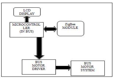
4.2.BUS MODULE
Fig.2 Block Diagram of Bus
The second module present in the RTQS is bus
module. Bus module also use ATMEL
microcontroller, which control the whole block in the bus module. ZigBee Transceiver is used as bridge between bus module and bus stop module. ZigBee, which is present in this module receive query from the bus stop module and transmit response to the bus stop module.ZigBee is connected to microcontroller through serial interface.
4.3 .BUS STOP
Fig. 3 Block Diagram of Bus Stop
53 with microcontroller. LCD display is used to display
the response, which is received from the bus module. Control switch is used to choose the operating mode of bus stop
4.3.1ZIGBEE COMMUNICATION
Zigbee is low power and low cost which will help this system to be deployed in remote areas as well, where power and cost are major concern. Zigbee Communication between Bus and Bus Stops are the major concern of this paper. The reason Zigbee is given priority over the other short range wireless technologies like WiFi is that in this research only few bytes of data is to be transferred using short range communicate with each other through Zigbee. Since Control Centre is aware of all the ongoing and carrying all the information about all the buses and bus stops, the information is first transferred to corresponding bus stop about the upcoming bus. Bus Stops and Control Centre are always connected to each other through the internet (Wired or Wireless) so information between Bus Stops and Control Centre can be easily shared. Major concern is the transfer of information between the Bus Stops and Buses and that is to be done through Zigbee. This is the core of this research and so the information transfer between the Buses and the Bus Stops are carefully thought of. The sequence of information transfer between Buses and the Bus Stops through Zigbee. As soon as Bus enters the communication range of the Bus Stop, information exchange starts
The information between Buses and Bus Stops will be transferred through a low power and low cost wireless technology, ZigBee. The Antenna is placed at a certain height on the Bus Stop so that maximum clear light of sight is achieved while communication between Bus and the Bus Stops. The operation of ZigBee and the type of data that is going to be transferred through and from Buses and Bus Stops are beyond the scope of this paper.
4.3.2MICRO-CONTROLLER
The AT89C52 is a low-power, high-performance CMOS 8-bit microcontroller with 8K bytes of in-system programmable Flash memory. The device is manufactured using Atmel’s high-density nonvolatile memory technology and is compatible with the industry standard.80C51 instruction set and pin out. The on-chip Flash allows the program memory to be reprogrammed in-system or by a conventional nonvolatile memory programmer. By combining a versatile 8-bit CPU With in-system programmable flash on a monolithic chip. The AtmelAT89S52 is a powerful micro controller, which provides a highly flexible and cost-effective solution to many embedded control applications. The AT89S52
provides the following standard features: 8K bytes of Flash, 256 bytes of RAM, 32 I/O lines, Watchdog timer, two data pointers, three 16-bit timer/counters, a six-vector two-level interrupt architecture, a full duplex serial port, on-chip oscillator, and clock circuitry. In addition, the AT89S52 is with static logic for operation down to zero frequency and supports two software selectable power saving modes. The Idle Mode stops the CPU while allowing the RAM, timer/counters, serial port, and interrupt system to continue functioning. The Power-down mode saves the RAM contents but freezes the oscillator, disabling all other chip functions until the next interrupt or hardware reset. More information please refer Data sheet 0f AT89S51.
Features of AT 89C52 Microcontroller 1. 8K Bytes of In-System Programmable 2. 4.0V to 5.5V Operating Range 9. Interrupt Recovery from Power-down Mode 10. Watchdog Timer
11. Dual Data Pointer Power-off Flag
4.3.3DISPLAY
54
All inputs are TTL compatible. Each output is a complete totem-pole drive circuit, with a Darlington transistor sink and a pseudo- Darlington source. Drivers are enabled in pairs, with drivers 1 and 2 enabled by 1,2EN and drivers 3 and 4 enabled by 3,4EN. When an enable input is high, the associated drivers are enabled, and their outputs are active and in phase with their inputs. When the enable input is low, those drivers are disabled, and their outputs are off and in the high-impedance state. With the proper data inputs, each pair of drivers forms a full-H (or bridge) reversible drive suitable for solenoid or motor applications.
5.APPLICATIONS
1. In public transport service.
2. It can be used search engine for searching near by famous places like restaurants famous parks and other famous cultural places.
3. Behave like a guide for new person
6. EXPERIMENTAL RESULT:
6.1 CONTROL STATION SETUP:
Fig.4 Control Station Setup
Fig.5 LCD display at Control station
The essential components in control station modules is keypad,zigbee,microcontroller,LCDdisplay.Number of passanger entering in the bus is done by using kekpad.By pressing key number one or two the message of starting bus is sent to the bus . In figure 5 Bus is starting and go toward which station through which path is displayed on LCD.
6.2 BUS STOP SETUP:
Fig.6 Bus Stop Setup
Fig .7 LCD display at Bus stop
The essential components of bus stop module is Zigbee, Microcontroller ,LCD display etc.control station transmit the information of bus like number of passenger in the bus ,bus come through which path is displayed on LCD of figure 7.
6.3 BUS SETUP:
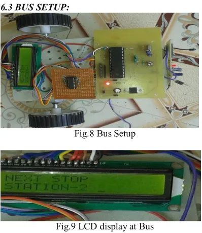
Fig.8 Bus Setup
Fig.9 LCD display at Bus
The essential parts of Bus module motor driver, microcontroller, Zigbee ,LCD display this setup receive the message from control station like starting of the bus ,go to the next station through which path . In figure 9. the no of passengers in the bus and bus is go to which station through which path is displayed on LCD.
7.CONCLUSION
55
according to the demand of the passenger. The system can fulfil the demands of the passengers in a way that they have to wait less on the Bus Stops and even if they miss the Bus they can be entertained by the next bus without waiting for very long. The use of Zigbee for communication between the Buses and the Bus Stops greatly reduce the total cost of the system. Everything is connected to the Control Centre which is the brain of the system. Control Centre and Bus Stops are connected through the internet and Buses and Control Centre are connected to each other through Bus Stops. All the characters (Buses, Bus Stops and Passengers) are updated with latest information all the times which makes The Flexible Bus Systems more information rich and reliable.
REFERENCES
[1] Vanajakshi, L., Subramanian, S.C. and Sivanandan, R., “Travel time prediction under heterogeneous traffiz conditions using global positioning system data from buses”, IET Intelligent Transport Systems, Volume: 3, Issue: 1, Page(s): 1 – 9, 2009.
[2] M.G.H. Bell, “Policy issues for the future intelligent road transport infrastructure”, IEE Proceedings Intelligent Transport Systems, Volume:153 , Issue: 2, Page(s): 147-155, 2006.
[3]Peter Tarasewich, Robert C. Nickerson and Merrill Warkentin, “Wireless/Mobile E-Commerce: Technologies, Applications, and Issues”, Seventh Americas Conference on Information Systems, 2001.
.
[4] Roy, S.; Sen, R.; Kulkarni, S.; Kulkarni, P.; Raman, B.; Singh, L.K., “Wireless across road: RF based road traffic congestion detection”, Third International Conference on Communication Systems and Networks (COMSNETS), Page(s): 1- 6, 2011.
[5]Seong Hoon Kim; Jeong Seok Kang; Hong Seong Park; Daeyoung Kim; Young-joo Kim, “UPnP-ZigBee internetworking architecture mirroring a multi-hop ZigBee network topology”, IEEE Transactions on Consumer Electronics, Volume: 55, Issue: 3, Page(s): 1286 - 1294, 2009.
[6] Peng Ran; Mao-heng Sun; You-min Zou, “ZigBee Routing Selection Strategy Based on Data Services and Energy-Balanced ZigBee Routing”, IEEE Asia-Pacific Conference on Services Computing (APSCC '06), Page(s): 400 – 404, 2006.
[7] Suzuki, N.; Mitani, T.; Shinohara, N., “Study and development of a microwave power receiving system for ZigBee device”, Asia-Pacific