BUCKLING OF CYLINDRJCAL SHELLS
Thesis by
James Herbert Starnes, Jr.
In Partial Fulfillment of the Requirements For the Degree of
Doctor of Philosophy
California Institute of Technology Pasadena, California
1970
JAMES HERBERT STARNES, JR.
ACKNOWLEDGMENT
The author wishes to take this opportunity to sincerely thank Dr. E. E. Sechler for the patience and guidance he generously extend-ed during the course of this investigation. The advice and useful
comments of Drs. C. D. Babcock and J. Arbocz are also appreciated. The author also thanks Miss Helen Burrus for patiently typing the manuscript, Mrs. Betty Wood for preparing the graphs and
figures, and the employees of GALCIT who cheerfully provided their assistance.
The financial aid provided by the Lockheed Aircraft Corporation, the Northrop Corporation, the Ford Foundation, and the Del Mar
ABSTRACT
An experimental and theoretical investigation of the effect of a circular hole on the buckling of thin cylindrical shells under axial compression was carried out. The experimental program consisted of tests performed on seamless electroformed copper shells and Mylar shells with a lap joint seam. The copper shells were tested in a controlled displacement testing 1nachine equipped with a noncontacting
surface displacement measuring device. Three-dimensional surface plots obtained in this manner showed the changes in the displacement field over the entire shell, including the hole region, as the applied load was increased. The Mylar shells were tested in a controlled load testing machine and demonstrated the effect of increasing the hole radius on the buckling loads of the cylinder.
The theoretical solution was based on a Rayleigh-Ritz
approximation. The solution provided an upper bound for the buckling stresses of the cylinders tested for hole radii less than ten per cent of the shell radii. The theoretical solution also identified the gov-erning parameter of the problem as being related to the hole radius, the shell radius, and the shell thickness.
The theoretical part of the investigation showed that even a small hole should significantly reduce the buckling stresses of
the character of the shell buckling was dependent on the hole size. For very small holes the shell buckled into the general collapse configuration and there was no apparent effect of the hole on the buckling mode of the shell. For slightly larger holes the shell still buckled into the general collapse configuration, but the buckling
stresses of the shell were sharply reduced as the hole size increased. For still larger holes the buckling stresses did not decrease as
TABLE OF CONTENTS
PART PAGE
I INT RO DU CT ION 1
11 EXPERIMENT 4
A. MYLAR SHELLS 4
1. Fabrication of the Mylar Shells 4
2. Equipment and Procedure for the 6 Mylar Shell Tests
B. COPPER SHELLS 8
1. Fabrication of the Copper Shells 8
2. Equipment and Procedure for the 10 Copper Shell Tests
c.
RESULTS OF THE EXPERIMENT 14l. Mylar Shells 15
2. Copper Shells 22
Ill ANALYSIS 25
A. DEVELOPMENT OF THE ANALYSIS 25
B. RESULTS OF THE ANALYSIS 36
IV CONCLUSIONS 38
REFERENCES 41
APPENDIX I 43
APPENDIX II 45
TABLES 54
LIST OF TABLES
TABLE PAGE
I Results of Mylar Shell Experiments with 54 Loads Applied at Top Plate Center
II Local Buckling Results of Mylar Shell 61
Experiments with Loads Applied Along Loading Diameter
III Copper Shell Results 70
FIGURE 1 2 3 4 5 6 7 8 9 10 11 12
LIST OF FIGURES
Mylar Shell and Test Apparatus
Mylar Shell Loading Plane and Hole Coordinates Copper Shell and Test Apparatus
Copper Shell Data Acquisition System
Summary of Buckling Loads for Mylar Shells Buckling Loads of Shell 6
Buckling Loads of Shell 7 Buckling Loads of Shell 14 Buckling Loads of Shell 17 Buckling Loads of Shell 20
Local Buckling of a Mylar Shell for µ
>
2 General Collapse of a Mylar Shell for µ>.
2 13 Assumed Applied Stresses and Applied StressPlane Geometry 14 15 16 17 18 19
Summary of the Buckling Stresses and Analysis for all Shells
Buckling Stresses of Shell 6 Buckling Stresses of Shell 7 Buckling Stresses of Shell 14 Buckling Stresses of Shell 17 Buckling Stresses of Shell 20
20 Effect of Load Location on the Buckling Loads and Stresses of Shell 7
FIGURE 21 22 23 24 25
26
27 2829
30 31 32 33 34 35 36LIST OF FIGURES (cont'd)
Effect of Load Location on the Buckling Loads and St res se s of Shell 6
Summary of Buckling Loads for Mylar Shells Summary of Buckling Stresses for Mylar Shells
Buckling Loads of Shell 6 Buckling Loads of Shell 14 Buckling Loads of Shell 20 Buckling Stresses of Shell 6 Buckling Stresses of Shell 14 Buckling St res se s of Shell 20
Effect of Slots on the Buckling Loads of Shell 7 Shell C3 Stress Distribution
Shell C6 Stress Distribution Initial Surface of Shell C5
Prebuckling Displacement of Shell C5 at S/SCL
=
O. 47Displacement of Shell C5 After Local Buckling Initial Surface of Shell C3
37 Prebuckling Displacement of Shell C3 at S/SCL
=
O. 13638 Prebuckling Displacement of Shell C3 at S/SCL
=
O. 38039
Displacement of Shell C3 after Local BucklingFIGURE 40
LIST OF FIGURES (cont'd)
Initial Surface of Shell C6
41 Prebuckling Displacement of Shell C6 at S/SCL ::: 0. 174
42 Prebuckling Displacement of Shell C6 at S/SCL
=
0. 39843 Displacement of Shell C6 After Local Buckling 44 Results of Analysis
PAGE 113
114
LIST OF SYMBOLS
a
B
D E F
I
0 0 0 0 0 0
N , N , N , N , N,i.., N ,i.. x y xy r ~ r~
p PCL
Hole radius
Undetermined coefficients of assumed displacement function
Geometric properties given in Appendix I Non- zero constants of equation ( 14) defined in Appendix II
Constant decay parameter associated with the assumed displacement function
Matrices defined in Appendix II Matrix defined by equation (25) Constants in equation ( 17)
Young's modulus Stress function
Functions defined in Appendix II
Identity matrix
Functions defined in Appendix II Stress resultants
Prebuckling stress resultants Axial load applied at shell center
PNH
q
R
r, cj>
s
t
ub, u , u
m ww
x,y
y
II
µ
LIST OF SYMBOLS (cont'd)
Measured buckling load of cylinder without a hole
Axial load applied at a distance Y from the shell center
Ba
Shell radius
Polar coordinates with origin at hole center Applied compressive stress
Classical buckling stress Stress due to PNH
Applied compressive stress due to Py Shell thickness
Strain energies defined on pages 26 and 27 Radial deflection of shell
Axial and circumferential coordinates
Distance from shell center to applied load Py Pois son's ratio
1 2 a
] 114
2 1/2
I. INTRODUCTION
Many authors have investigated the effect of axial compression on the buckling of complete cylindrical shells .and several explanations have been offered to try to account for the difference observed between theory and experiment. In recent years, several authors (for example, Refs. 1 and 2) have investigated the effect of initial imperfections as a cause for this discrepancy. Generally, these imperfections were in the form of waves in the surface of the cylinder. It was found that the presence of initial imperfections did significantly reduce the buckling
stress of a cylinder to a value below the generally accepted classical value given by:
1 Et
1f
where E is the modulus of elasticity, v is Poisson's ratio, t is the shell thickness, and R is the shell radius.
Surface waves are not the only type of imperfection that can be found in a cylindrical shell. In the applications of thin shell structures
it is often necessary to design a cylindrical shell with a circular hole in the form of an access port in a missile skin or aircraft fuselage, a ship hatch, or for numerous other reasons. Such a cylindrical
structure might be required to carry a static compressive load or, in the case of an aircraft or missile, fluctuating flight loads which have
buckling of the structure. Since imperfections in the form of initial surface waves have been shown to reduce the buckling stress of a
cylinder, it must be expected that a hole will also have an effect on the buckling stress of the cylinder.
It was the purpose of this investigation to determine the effect of a single circular hole on the buckling of a thin circular cylinder under axially compressive loads. This was done by performing two
series of experiments, one on Mylar, and one on copper shells.
Sufficient variations of the geometric parameters R/t and a/R, where a is the hole radius, were studied to insure the availability of enough data to be able to draw proper conclusions. The parametric ranges
considered were 400 !::. R/t !::. 960 and 0 !::. a/R !::. O. 5. The experi-ments provided measureexperi-ments of buckling loads, shell displaceexperi-ments,
and the distribution of the stresses applied at the ends of the shells. The results of these experirrlents were correlated on the basis of a theoretical parametric study performed by means of a Rayleigh-Ritz approxirrlation.
During the completion of this thesis, several authors have reported the results of similar investigations. Brogan and Almroth (Ref. 3) carried out a theoretical and experimental investigation of the effect of rectangular holes on the buckling loads of cylinders. Their theoretical results were obtained by a numerical solution of the
governing nonlinear equations of the problem. This proved to require large amounts of digital computer time for each buckling load, and therefore placed economic limits on the extent of their parametric
buckling loads of cylinders in the parametric range 162 ~ R/t ~ 331 with a single circular hole in their sides. Based on the results of his
experiments, Tennyson has suggested that the buckling load of a cylinder with a circular hole in its side is related to the parameter a/R. His results were nondimensionalized by dividing each experi-mental buckling load by the previously measured buckling load of the cylinder without a hole, a form of presentation which is useful for showing how a particular hole will effect a particular shell. For a cylindrical shell under axial compression the above technique is not the most conclusive method for the purpose of making a parametric
study. Due to the large scatter in buckling loads experienced for cylinders without holes under axial compression, using such buckling loads as nondimensionalizing parameters has the effect of introducing a variable reference into the parametric study and may provide
unreliable conclusions. It is shown in this thesis that the governing 2
II. EXPERlMENT
The experimental portion of this investigation consisted of two series of tests. The first series was performed on DuPont's "Mylar" polyester film, and the second series was performed on
electro-formed copper shells. The properties and characteristics of these two materials are such that different, but supporting, information was obtained from each series of tests.
A. MYLAR SHELLS
Mylar provided an inexpensive material that, for moderate thicknesses, was easy to handle. Under the loads applied during the experiment, this material remained elastic after the shell had
buckled, so long as excessive displacements were prevented. It was this characteristic that made Mylar useful as a test material. A shell could be buckled many times without any noticable degradation of the test specimen. As a result, it was possible to test the same shell for an extensive range of hole radii, and therefore compare the effect of increasing the hole size on the buckling load of a particular shell.
1. Fabrication of the Mylar Shells
The Mylar shells were constructed from material taken from available roll stock with nominal thicknesses of O. 005, O. 0075, and 0. 010 inches. Actual measurements showed these values to be
accurate to within 2. 4 per cent, with the 0. 005 inch thickness varying the most. Sheets of the appropriate size were cut from the rolls, and rectangles of the correct dimensions were drawn on these sheets
rolls, these sheets had a tendency to curl. To reduce residual
stresses due to fabrication, the rectangles were drawn on the sheets so that the circumference of the resulting cylinder would correspond to the curling of the sheet.
The sheets were cut to the required dimensions on a sheet metal shear. The shear blade was sharpened and adjusted so that it provided uniform cuts. The dimensions of the resulting rectangles were accurate to within 0. 0 I inches. A lap joint was prepared by
slightly roughening the two edges to be joined with fine emory paper. The rectangle was attached to an 8 inch diameter wooden mandrel, and Narmco 7343 /7139 cryogenic adhesive was applied to the prepared lap joint. This adhesive was selected as the seam bonding agent
because it provides a flexible seam which was demonstrated by buck-ling one cylinder over 600 times without any apparent damage to the
seam. The cylinder was allowed to remain on the mandrel for
approximately twenty-four hours with an aluminum bar clamped along the seam. The bar exerted enough pressure on the seam to force out an·y excess adhesive and to provide a reasonably uniform seam
thickness. Waxed paper was used to keep the bar and the mandrel from sticking to the cylinder. It was necessary to allow the seam to cure at room temperature for an additional week.
staples prevented the cylinder from pulling out of the Cerrolow during buckling or when a bending moment was applied to the shell.
The resulting cylinders were 8 inches in diameter and 10 inches long. Each cylinder had a seam that was approximately 0. 5 inches wide and had average thicknesses of 0.0115, 0.0168, and O. 0217 inches for nominal cylinder thicknesses of 0. 005, 0. 0075, and O. 010 inches respectively. Since the seams were made of both Narmco adhesive and Mylar, it was necessary to determine the modulus of elasticity of the seam. This was done by testing seam
specimens in a small tension testing machine. The average value of the modulus of elasticity of the seam found in this manner was 6. 51 x
1
o
5 psi. In a similar fashion it was found that the modulus of elasticity of pure Mylar was 7. 25 x 105 psi. Poisson1s ratio wasassumed to be equal to O. 3 for these experim.ents. The Cerrolow alloy provided clamped edge conditions for the cylinders.
2. Equipment and Procedure for the Mylar Shell Tests The Mylar shells were tested in the controlled load testing machine shown in Fig. 1. The load was applied at a point on the top end plate ("top plate") by means of a loading screw, a calibrated load cell, and a ball bearing in a hemispherical cup. The top plate had small holes drilled along one of its diameters ("loading diameter") which were 0. 125 inches apart for three inches on either side of the top plate center. There was also a small hole at the top plate center. At the time the top plate was attached to the cylinder, the loading
diameter was positioned so that it formed a plane ("loading plane11 )
the holes to be drilled in the cylinder wall. The loading plane is
shown in Fig. 2. The shell was positioned under the loading screw by locating one of the small holes on the loading diameter directly under the center of the loading screw. This was done by means of a
carpenter's plumb line which could be attached to the loading screw. The hemispherical cup was then placed in the correct position by inserting a short pin on its undersurface into the proper loading dia-meter hole, and the load cell was installed between a ball bearing
recessed in the end of the loading screw and the ball bearing in the hemispherical cup. The ball bearings were used to reduce torsional loads during the application of the desired axial load.
Since the shells made from 0. 005 inch thick Mylar stock were more difficult to handle and test than the thicker shells, it was
necessary to use a lighter top plate and more flexible load cell for these shells. The load cells were calibrated in a 3000 pound Riehle Brothers testing machine, and their spring constants were found to be 2. 5 and O. 714 pounds per 0. 001 inch deflection of the load cell dial gages.
were cut using a cross-cut dental drill and aluminum hole templates as guides. All hole edges were finished by trimming off any excess material with a sharp knife. For each hole size the value of the buck-ling load applied at the top plate center (cylinder axis) was always measured. At buckling there was an audible snap and a noticeable
de-crease in the load indicated by the dial gage. The buckling loads were also measured at various other positions along the loading diameter until a maximum buckling load was found. This procedure continued until the largest desired hole was cut in the shell and tested, or the
shell collapsed catastrophically as in the case of some 0. 005 inch thick shells. Each buckling load was applied at least three times to check the repeatability of the experiment. As demonstrated by the repeat-ability of these loads, Mylar is well suited for this type of experiment.
B. COPPER SHELLS
The copper shells were used to provide information about the displacements normal to the shell surface, the presence of other initial imperfections, and a measure of the distribution of the applied load around the circumference of the shell. These shells were more sensitive to handling, more difficult to manufacture, and more
expensive than the Mylar shells. However, they provided much useful information that could not be obtained from the Mylar shells.
1. Fabrication of the Copper Shells
The copper shells were manufactured by the electroforming process using the electroplating facilities of GALCIT•:<. The
manufacturing procedure and electroplating facilities are completely de scribed in reference 1. A layer of wax was applied to a steel mandrel and then turned on a lathe to the desired shell diameter. The wax was then sprayed with a silver suspension to provide an electrically conducting surface, after which it was placed in the GALCIT electroplating facility where the desired amount of copper was deposited on the mandrel. The plating solution used was copper fluoborate. After plating, the shell was rinsed and cut to the desired dimensions on a lathe. A fly cutter was used to cut the hole in the cylinder while the shell was still on the mandrel. Each plated
mandrel provided one test shell, one short calibration shell, and four 0. 25 inch wide strips of copper. The resulting copper test shells were 8 inches in diameter and 8 inches long. The shell was removed from the mandrel by melting the wax. A benzene bath was used to
remove any excess wax or silver from the shell. The shell was weighed and an average thickness was determined by using a specific gravity equal to 8. 9 for the resulting copper. Subsequent preloading
surface measurements showed no apparent bending of the shell around the hole due to the cutting of the hole.
The four 0. 25 inch wide copper strips were mounted in an Instron tension testing machine and were tested to determine the modulus of elasticity of the test specimens. The average value of the modulus of elasticity was 13. 98 x 106 psi. A value of O. 3 was
2. Equipment and Procedure for the Copper Shell Tests The copper shells were tested in a controlled displacement testing machine. The testing machine and data acquisition equipment
are thoroughly described in reference 2. The testing machine, shown in Fig. 3, consisted of two heavy flat steel plates which were separated by four threaded steel shafts. The shafts were controlled by a gear
system that could turn the shafts simultaneously or allow each shaft to be turned independently for purposes of adjustment.
A calibrated load cell was attached to one of the steel plates with Devcon1 s 11Plastic Steel11• This load cell was a short 8 inch
di-ameter brass cylindrical shell to which were attached twenty-four foil
type strain gages. These strain gages were mounted in pairs every 30 degrees around the circumference of the load cell. One gage of each pair was mounted on the inside surface and one on the outsdie surface of the load cell. Each pair of strain gages was connected in series to the strain gage switching and balancing unit to avoid measuring any bending stresses in the load cell. One end of the copper test shell
specimens was mounted on a short 8 inch diameter spacer shell by the use of Cerrolow alloy. The other end of the specimens was similarly bonded to the load cell, and the spacer shell was then bonded to the
remaining steel plate by the use of 11 Plastic Steel".
passed through the supporting steel plate of the testing machine (see details in reference 2). The drive system was designed to position the end of the shaft holding the pickup in such a manner that it was possible to scan all points on the inside surface of the test shell with the pickup. To make a mapping of the shell surface the shaft and pickup were driven circumferentially through 360 degrees. The shaft was then advanced axially 0. 24 inches, and another circumferential
scan was made. This continued automatically until the entire test shell length had been traveled.
During the course of the experimental program both inductance and capacitance type pickups were used and both types worked equally well. The distance from the inner surface of the shell to the end of the pickup was represented by an electrical signal which was trans-mitted to the data acquisition system by means of the pickup signal
carrier system. The carrier system for the inductance pickup is described in reference 2, and the modifications necessary for the capacitance pick up are described in reference 6. A voltage corres-ponding to the distance from the shell to the pickup was measured by
a digital voltmeter and recorded on cards by an IBM 526 card punch. The signal was also monitered on an xy-analog plotter. The copper shell data acquisition system is shown in Fig. 4. The short copper calibration shell manufactured with the test shell was used to calibrate the pick up for each test. This was done before mounting the test shell in the testing machine. The voltages corresponding to known
Tests were run to determine the effect of the hole in the shell on the pickup signal. Only when the pickup passed over a part of the hole was there noted any influence of the hole on the pickup signal.
After a test specimen was mounted in the testing machine, the strain gage outputs were set to zero and an initial scan was made with no load applied to the shell. This scan gave a measure of the initial imperfections in the shell and provided a reference surface corres-ponding to the no-load condition. The first loading increment was applied to the shell by turning the threaded shafts of the testing machine. The shafts were adjusted until the load was uniformly distributed around the load cell. At this low initial stress level, it was assumed that the hole in the cylinder was far enough from the load
cell not to influence the stress field at the load cell. The distance from the load cell to the edge of the largest hole tested was 4. 5 hole diameters. A scan was then made of the shell surface at this load level. The loading procedure was continued until buckling occurred. At buckling there was an audible snap and a decrease in the strain
indicated by the strain gage aligned with the hole. To avoid premature buckling of the shell, no adjustment was made in the applied load
distribution once half of the expected buckling load had been applied, however the strain gages were monitored at each loading increment which allowed any change in the stress distribution to be recorded.
the distance from the pickup to the shell surface using the calibration polynomial. A reference "perfect" shell was computed by the method of least squares from the data of the initial surface scan. All
distances from pickup to shell surface were then referenced to this
11perfect11 shell. A three-dimensional plotting routine allowed the
C. RESULTS OF THE EXPERIMENT
The results of the experimental program indicate that a
circular hole in the side of a cylinder can influence the buckling load of the cylinder. Experimentally, it was found that the effect of a
small hole is masked by the effects of initial deformations but, at larger hole radii, the reduction in buckling stress took the form predicted by the analysis. The analysis given later and the experi-mental results presented in this section indicate that the buckling loads of a cylinder with a hole in its side are related to a 2
I
Rt.All results are expressed as a function of the nondimensional parameter
Lekkerkerker (Ref. 7) has shown that this parameter governs the solu-tion of the pre buckling stress distribusolu-tion and displacements and it is
reasonable to assume that any attempt to solve the buckling problem as a small perturbation about Lekkerkerker' s pre buckling solution would also involve the parameter µ.
(for example, Ref. 8). For a constant applied stress, the magnitude of the maximum membrane stress at the hole will incre-ase
signifi-cantly above the flat plate value as µ increases. The bending stresses are always much smaller than the membrane stresses.
1. Mylar Shells
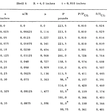
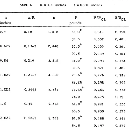
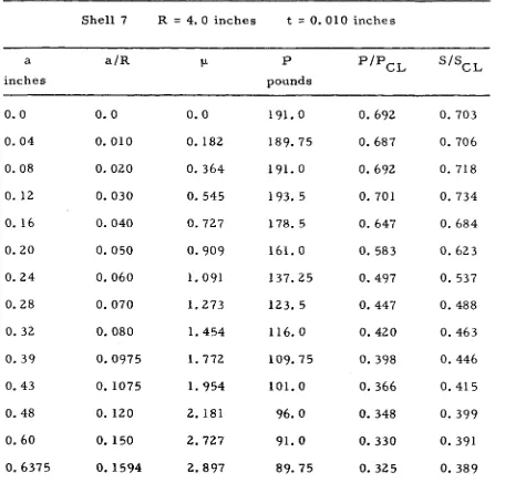
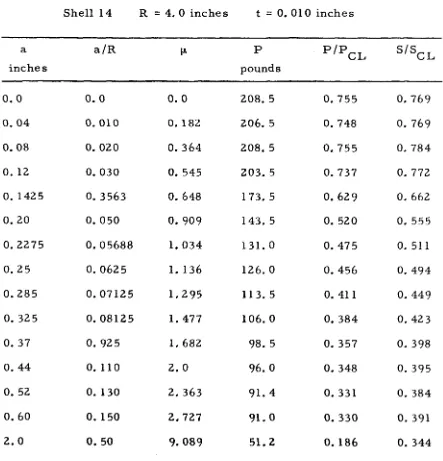
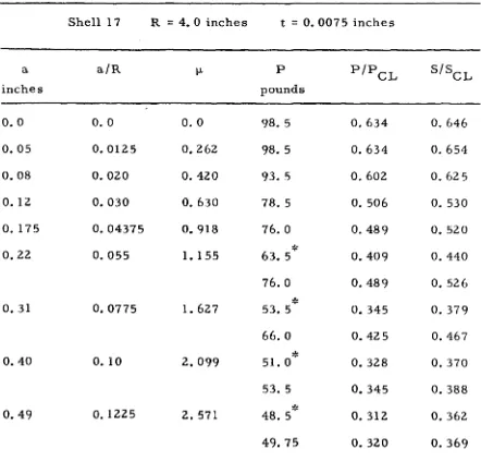
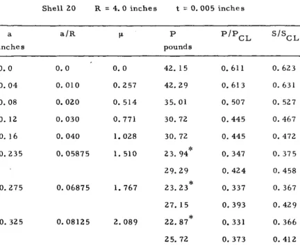
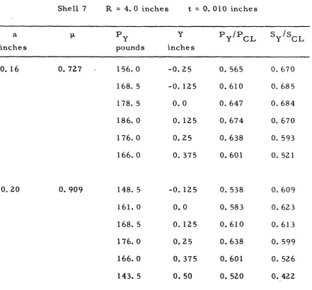
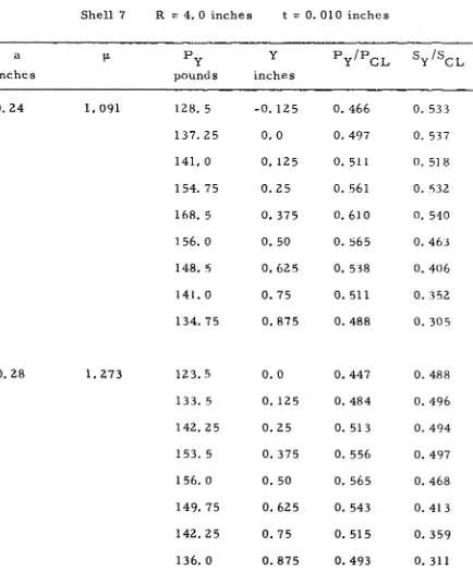
The results of the experiments with Mylar cylinders show that the buckling characteristics of a shell with a hole in its side depends on the value of the parameter µ. The measured buckling loads applied at the center of the top plate were nondimensionalized by the classical buckling load of a cylinder without a hole, and a summary of these results for twelve shells is shown in Fig. 5. Similar results for some representative cylinders with various R/t ratios are shown in Figs. 6 through 10 and presented in Table I. The classic al buckling load for a cylindrical shell without a hole was used as a nondimen-sionalizing parameter because it introduces the modulus of elasticity into the experimental results and provides a constant reference when comparing results for different shells with the same dimensions.
shell buckles into the general collapse mode due to some other imper-fection. There were usually two axial and six circumferential full waves in the buckled shell. For some cases in this range (Figs. 7 and 8), the buckling load rises slightly or appears to be erratic as µ
increases. Since the hole is believed to have no effect on the buckling load in this range, this behavior is attributed to slight eccentricities in the shell. Although care was taken to align the loading diameter of the top plate with the intended loading plane, it is probable that slight eccentricities existed. Since the centroid of the shell was assumed to be in the loading plane, such eccentricities would cause a combined loading of pure axial compression and possible bending about two axes. This, of course, would cause unexpected stress levels or erratic
behavior.
For values of µ between O. 4 and 1. 0 the buckling loads
dropped sharply as µ increased. The shell still buckled in to the dia-mond pattern, but the hole was located on a diadia-mond ridge or the
The slightest lateral disturbance near the hole would cause the shell to buckle when the applied load was slightly below the known buckling load of the shell.
For values of µ greater than 2. 0 the Mylar shells always snapped into the stable local buckling state shown in Fig. 11. The maximum displacement at the hole was on the order of 0. 25 inches, which is many times the shell wall thickness. Apparently the stress
concentration around a hole in this range of µ is sufficient to cause local buckling to occur before enough load could be applied to make the shell sensitive to disturbances which would cause general collapse. As a result of local buckling the dial gage of the load cell indicated a
slight relaxation of the applied load of from one to three pounds. This represents a displacement of the top plate of as much as O. 001 inch. As seen in Fig. 11, the local buckling occurs roughly in the form of
an ellipse with semi-major axes parallel to the y-axis of the hole coordinates shown in Fig. 2. The initial length of these semi-major axes seemed to depend on the hole size. After local buckling had occurred it was possible to resume the loading of the cylinder. This continued until the shell finally buckled into the general collapse state shown in Fig. 12. During this additional loading, the lengths of the semi-major axes of the local buckling ellipses increased as the addi-tional load was applied. The applied load required for the general
collapse of these shells was equal to or slightly greater than the load required for local buckling. The general collapse load was never more than 17 per cent above the local buckling load. Figures 6 and
general collapse loads. Prior to local buckling the shell was quite sensitive to slight disturbances. When the applied load was just below the local buckling load any lateral disturbance would cause local buckling to occur in the hole region. Once local buckling had occurred the shell did not seem as sensitive to these disturbances as they seldom led to general collapse. Buckling loads continued to decrease as the hole radius increased, but the rate of decline was significantly less than that of the range of µ between 0. 4 and I. O. For values of µ between I. 0 and 2. 0 there is a transition between the sharp decline in buckling load for µ between O. 4 and I. 0 and the milder decline of µ greater than 2. 0. In this range of µ the shell would buckle into either the general collapse or the local buckling mode. The differences between local buckling and general collapse loads was usually greater in this range than they were for µ greater than 2. O. This behavior is shown in Figs. 9 and 10. Figure 7 shows the results of a shell for which only general collapse was observed,
and Fig. 8 shows the results of a shell for which the general collapse loads were the same as the local buckling loads.
applied stresses and applied stress plane geometry are shown in Fig. 13. Since the applied stresses vary as the cosine of the meridional angle 8, little error is introduced by assuming a constant stress level applied to the cylindrical generators near the hole. Consequent-ly, it is assumed that the membrane stresses applied to points Hl and HZ of the hole edge can be used to represent the applied buckling
stress corresponding to local buckling of the shell. This assumption is justified by the local buckling observed in the hole region. Based on the geometry of the applied stress plane shown in Fig. 13, the membrane stresses applied to points Hl and HZ are given by
where A, r1,Y G' and a are given in Appendix I. The resulting applied buckling stresses were nondimensionalized by the classical buckling
stress of a cylinder without a hole, and a summary of these results for twelve shells is shown in Fig. 14. Similar results for some representative cylinders are shown in Figs. 15 through 19. Here again any erratic behavior of the results is attributed to eccentricities in the loading plane. Since the larger holes were cut by hand using a template, it is certainly possible that slight misalignment of some holes occurred. This, or any other eccentricity, would cause a
higher applied stress on one side of the hole and would cause the shell to buckle at a different applied stress level.
along the loading diameter. This introduces the possibility of both local buckling at the hole and buckling of the seam. Seam buckling will occur when the applied load at any point on the loading diameter causes the buckling stress of the seam to be achieved before the buckling stress of the hole. The stress at points HI and H2 due to a load applied at any point on the loading diameter is given by
Sy 0
Py [
*
+
f
1 ( Y G - Y )(Y G+
R cos°'
~
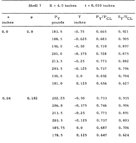
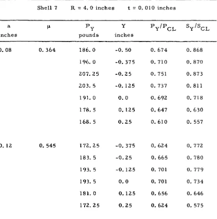
where Y is the distance from the cylinder axis to the applied load. Buckling loads were measured and buckling stresses computed for loads applied along the loading diameter for various values of µ.
Results for two representative shells are shown in Figs. 20 and 21 and presented in Table II. These results show that the applied loads have maximum values which are seldom located at the top plate
center. Buckling loads to the right of a maximum load in Figs. 20 and 21 correspond to buckling of the seam, while those to the left correspond to buckling at the hole. Since the loading points on the loading diameter were 0. 125 inches apart, there was always the possibility of being as much as 0. 0675 inches from the location
represented by the nearly constant stress magnitudes to the left of the maximum loads in the figures. The slight negative slope of
some of these curves (for example, Fig. 21, µ
=
5. 567) is attributed to slight misalignment of the hole from the loading plane. Thesegment of the stress curves to the right of the maximum load with a large negative slope corresponds to buckling of the seam. These curve segments show that the seam buckled before the stress applied at the hole caused buckling at the hole. The two curves (Fig. 20,
µ = 0 and µ = 0. 182) which have large negative slopes on the left of the maximum load, represent results for values of µ in the range where the hole was not the predominant initial imperfection.
In an attempt to separate the effect of the hole from the effect of other initial imperfections, the results were nondimensionalized by the buckling loads measured at the top plate centers of the cylinders without holes. Summaries of the results of twelve cylinders for buckling loads and buckling stresses are shown in Figs. 22 and 23
respectively. Results for three representative shells are shown in Figs. 24, 25, and 26 for buckling loads and in Figs. 27, 28, and 29 for buckling st res se s. These results indicate the approximate reduction in buckling load of a cylinder with a hole in its side after the effect of initial imperfections has been removed.
irregularities were apparently small enough not to significantly
influence the local stress field. There was one noteworthy exception. In order to determine the sensitivity of points of high stress concen-tration to slight irregularities, a short O. 0625 inch wide slot was cut along the y-axis of Fig. 2. As the slot length increased, the buckling load actually increased. This increase in buckling loads is probably due to the relief of the local bending stress field in the hole region shown to exist by Lekkerkerker (Ref. 7). As the slot length further increased the shell buckled at the ends of the slots instead of at the hole and the buckling loads again decreased. The results of one such investigation are shown in Fig. 30 for a hole corresponding to µ
equal to 2. 897.
2. Copper Shells
The buckling stress results of the copper shell experiments fell within the scatter band of the Mylar shell results, and are shown in Fig. 14 and presented in Table III. The six shells tested had hole diameters ranging from 0. 24 to 0. 80 inches, and buckled into a
stable local buckling configuration in the hole region in all cases. Although the buckling stress results agreed reasonably well for the
controlled load testing machine used for the Mylar shell tests allowed top plate displacement to occur during local buckling. This type of displacement was prevented by the controlled displacement testing machine used for the copper shell tests. It is entirely possible that the local buckling pattern of the Mylar shells was initially the same as that of the copper shells, and that the top plate displacement and
corresponding applied load relaxation was sufficient to cause the Mylar shell local buckling pattern to change its orientation. In the copper shell tests the local buckling pattern maintained its original orientation when additional loading was applied.
The applied stress distribution, recorded by the strain gages on the load cell, showed that only the strain gage directly in line with the hole recorded any significant change due to local buckling. Since the strain gages were only 2. 135 inches apart, the effect of the hole on the stress distribution was verified to be a local effect by the fact that the strain gages on either side of the strain gage aligned with the hole indicated little change, if any, due to local buckling. Examples of the stress distribution for various loading increments are shown in Figs. 31 and 32. As seen in Fig. 32, even the large hole in shell C6 influenced the stresses of only three strain gages, and two of these only slightly. Once local buckling had occurred the
strain gage aligned with the hole remained at a constant stress level until general collapse occurred.
The results of the surface scans of three copper shells with relatively small, medium, and large holes are shown in Figs. 33
The initial surface scans, Figs. 33, 36, and 40, show that initial imperfections of several wall thicknesses in amplitude were present in all of these shells. The displacements of the shell surfaces due to various loading increments were obtained by subtracting the initial
scan data from that of the subsequent loading increments. Figure 34 represents the displacements of the surface of shell CS due to the loading increment (S/SCL = 0. 47) applied just prior to local buckling (S /SCL
=
0. S3), and shows that very little pre buckling displacement has occurred in the hole region. As shown in Fig. 3S, very large displacements of up to four or five wall thicknesses were measured in the hole region after local buckling had occurred in shell CS. The other region of large displacements in Fig. 35 is the result of local buckling occurring in another area of the shell just after the local buckling of the hole region. Figures 37 and 38 show the displacements of the surface of shell C3 for low and near local buckling stress levelsIII. ANALYSIS
A. DEVELOPMENT OF THE ANALYSIS
In order to predict the proper parameter to represent the
effect of a circular hole on the buckling stress of a cylinder, a simpli-fied analysis is presented based on the experience gained from the experiments. It is assumed that the critical buckling stress, defined by the local buckling phenomenon, can be obtained by treating the
problem as a linear eigenvalue problem. This implies that the general collapse phenomenon observed in the Mylar experiments for values of
µ less than 1. 0 was caused by local buckling. It also requires that the local bending stresses in the hole region, shown to exist by
Lekkerkerker, are assumed to make only a small contribution to the initial buckling of the shell and can be neglected. This assumption is supported by the small prebuckling displacements observed in the copper shell experiments for small values of µ. The analysis can be further simplified by assuming that the stress distribution of a flat plate with a hole closely approximates the membrane stress distribu-tion in the cylinder. This assumpdistribu-tion is justified by Lekkerkerker' s membrane stress results which approach the flat plate stress concen-tration values at the hole as the hole becomes small. Since the
To solve the problem, within the restrictions of the above assumptions, a coordinate system is adopted which has its origin in the mid-surface of the cylinder at the center of the hole as shown in Fig. 2. The governing equations are transformed into this coordinate system, a displacement function is assumed, and the local buckling stresses are computed by the Rayleigh-Ritz procedure. The displace-ment function assumed must become zero as the distance from the hole becomes large, and is not required to be zero at the hole. Its
derivative with respect to r must approach zero as the hole radius approaches zero in order to provide symmetry at the origin as the hole radius approaches zero.
A displacement function satisfying the above requirements is given by:
( 1)
where B is a constant which represents the decay of the local buckling displacement, and A
0 , A2, C0 , and
c
2 are undetermined coefficients. The trigonometric form of this function was suggested by the local buckling pattern of the Mylar shell experiments.The change in total potential energy due to buckling is given by:
u
=ub
+
u
w+
u
m(2)
U = 21
ff [
N° (w, )2 + N°(w, )2 +ZN°
w, w,J
dxdyw x x y y xy x y (4)
(5)
where N°, N°
x
y'
0
and N are the prebuckling stress resultants, a xy
subscript following a comma indicates partial differentiation, and
D
=
Also, by introducing a stress function F,
Nr
=
to-r= -
r l F, + r2
1 F, <!><!>r
N<I>
=
to-<I> -- F, rr(6)
Nr<j>
=
tr r<j>=
-(- F r l '<I> ' r )and the coordinate transformation
a
• <I>a
1a
ox
= smTr
+
r cos <I> ""§'Ci>( 7)
a
a
1 • <I>a
ay
= cos <I> or- -
r sm ""§'Ci>(8)
+ 2
,,r..!.
w, w,+
_J_z
w, w,.i....i..]}
rdrdcpr rr r rr 'l''I'
r
For the coordinate system shown in Fig. 2, the stress distri-bution in a flat plate with a circular hole given in reference 8 can be written as:
I 2
i
St( I
4 2
No
=
St(l a + 3 ~ 4~) cos 2 <I>-2
- z ) +r 4 2
r r r
No
=
- - St(l 1+ -
a2)
- z
1 St(l + 3 4 ) a4 cos 2 <I> cj> 2 2r r
(9)
1 4 2
No
=
- z
St(l 3~+
2~ ) sin 2 cj>r<j> 4 2
r r
where S is the magnitude of the applied compressive stress. By
using (7), (9), and the transformation
No
No . 2 0 2 0
sin 2 <I>
x
=
r sm cj>+ Ncj> cos
cj>+ Nrcj>
No
=
No cos2<)>+ N; sin
2cp
-N~cj>
sin 2<I>
y r
No =
.!.
(No xy 2 r(4) can be written as
Uw
= -
i
s{J{[
2 sin2<P- 3 :~cos
2<P+
::(4
cos 2 <P -I~
(w, /( 11)
+[,~
cos2.p
+
3~
cos 2 <P+
:~
]<w, / }
rdrd.pBefore expressing the final form of the membrane energy, it is necessary to determine the stress function F. This is done by solving the linear shallow shell compatibility equation
Et
1f
w,xx (12)which is consistent with the assumptions made for this simplified analysis. By using (I) and (7), equation (12) can be written as
where g
0 (r), g2(r), and g4(r) are given by (Al) of Appendix II. The
n_
2 2n
2F = a L.ur
+ b r
+ c r .i.nr+ d r
<j> + a' <j>c 0 0 0 0 0
( 14)
(a rn + b rn+Z +a' r-n + b' r-n+Z) cos n <I>
n n n n
00
+I:
n=Z
A particular solution of (13) will be determined by the method of variation of parameters. This is done by assuming that (13) is
satisfied by
(15)
where h
0 (r), h2(r), and h4(r) are to be determined. Substituting (IS) into (13) and using the linear independence of cos m<j> gives three ordinary differential equations of the form:
d4h d3h
(2m2+ 1) d 2
h
(1+2m2) dh
m+~ rn m
+
mdr4 r dr3 r 2 dr2 r 3 dr
4 2 (16)
+ m -4m h = g (r)
4 m m
where m = 0, 2, 4. The homogeneous forms of each of ( 16) have four independent solutions and are of the form:
hoc
co1
£nr + C 2 2 lnr + c 04= OZr
+ C03r
hzc
2 4 -2
(I 7)
= C2Ir +C22r +C23r +Cz4
h4c
4 6 -4 -2
= C41 r + C42r + C43r + C44r
Using ( 17) and applying the method of variation of parameters to (16) gives:
Et
I [
4 _ Br 4f
e -Br ] ho(r)=
BR AO B2 e - B2 - r - drh2 ( r) = Et
I
A e - Br [_±_
+
~
+
__£
l
8R 0 B2 B3r B4r2
- A2e -Br
l
r
B+
2
3
+
-3-6
+
"""4'2 -
6
l
A2rzp-Br
- r - dr B B r B r+
c
0e -Br[4_!_+
20+
48+
48
l
B2 B3 B4r B5r2c
2e -Br-[ 4r +
Q+
24+
2±_
JI
-
-;;z
B3B
4r Bsrzh
4 ( r) = 4R Et
I
A 2e - Br [ 1-;z
+
B3r 7+
B4r2 2 7+
_§_Q_
B5r3+
B6r4 6 0l
The integral in ( 18) is the exponential integral (Ref. 10) and, for convenience, will be replaced by
-z e
z dz= - E1(Br)
(18b)
(19)
where it is understood that E
1(oo) = O. Equations (15), (18), and (19) complete the particular solution of (13), and it is possible to write
F
=
F+
FThe constants in (14) are determined from the boundary conditions: N
r = 0 at r = a (21 a)
= 0 at r = a (21 b)
and the requirement that
N =N =N-..Q
r cj> rep as r becomes large (21 c)
It is also required that Nr, Ncj>, and Nrcj> are periodic with respect to cj> and that the strain energy be bounded as r becomes large. Since the problem is treated as a local phenomenon with w, Nr' Ncj>' and Nrcj> equal to zero and the strain energy being bounded as r becomes large, there is no loss of generality if r is allowed to go to infinity.
Therefore, integration over r will be taken to range from a to infinity in the energy exppres sions, and (21 c) will be taken to mean
N
r as r--+ oo (21c')
Applying these conditions and the linear independence of sin mcj> and cos m<f> give:
3.
from the periodicity of N
r
n ~ 3 from N = 0 as r --+ oo r
a' n
=
b' n=
c' n=
d' n=
0and
a ' 1 --
2
1 a2 b' 11 1 2 d'
cl
=
2
a 1from (2 la~ b)
5. (5), (6), and (20) give
for n ~ 5
u =
4rrf 00 [ (b 1 ) 2+ (
d' )z ]
.!_
m Et 1 1 r
a
(i)
(ii)
where M1 is the result of the other terms in (20) and is bounded.
Completion of the integration in (ii) gives
00
a
which becomes unbounded as r - oo, unless
(b' )2
+ (d' )
2=
0 (iii)1 1
Since (bl )2
>
0 and (dl )2>
0, (iii) can be satisfied only if bl = dl = 0Then (i), (iv) give
a' = c' = 0
1 1
Of the seven remaining constants, a 1 and c
1 are not required to determine Nr, N<j>, or Nr<j>' and therefore can be assumed to be equal to zero without any loss of generality. The remaining constants a
0, az, bz, a4,1 and b4, are determined by applying (2la, b) and are
given in (AZ) of Appendix II.
Since the constants in ( 14) have been determined, it is now possible to use the stress function to compute the stress resultants. Therefore, using (6) and (20) gives
where k.(r), i = I, 8 are given by (A3) of Appendix II.
1
By using equations (I), (5), (8), (II), and (22), it is now
(22)
possible to express the change in total potential energy due to buckling, (2), in terms of the undetermined coefficients A
0,A2,
c
0, andc
2. Applying the Rayleigh-Ritz procedure gives the four equationsau
au
aAo
=o; aAz
=o;
au
ac
=
O;0
aU
ac
=
02
(23)
AO
[BI - SBJ
A2 co = 0(24)
c2
where B
1 and B2 are two 4 x 4 symmetric matrices given by (A4) and (AS) of Appendix II. Pre-multiplying (24) by
Bz
1 and defining(25)
gives
=
0(26)
where I is the identity matrix. The eigenvalues, S, are then obtained from the determinant
B 3 - SI
1
=
0 (27)B. RESULTS OF THE ANALYSIS The elements of the matrix B
3 are functions of a, B, E, R, t, and v and contain several integrals which must be evaluated numeri-cally. Consequently the expansion of (27) and the determination of the eigenvalues were done numerically on an IBM 360/75 digital computer. The results were minimized with respect to the decay parameter B for each value of the hole radius. A range of R/t ratios was
plotted with respect to a 2 /Rt. These results are presented in Table IV and shown in Fig. 44 plotted with respect to the square root of a 2
I
Rt for convenience.The results of this analysis identify the parameter of the problem as being related to a2 /Rt, rather than just a/R. Following
Lekkerkerker' s results (Ref. 7), the parameter was assumed to be a 2
function of the square root of a /Rt, namely,
The dependence on Poisson's ratio was not confirmed by either the experimental or analytical results. The analytical results are com-pared with the experimental results in Fig. 14. As can be seen in Fig.
14, the analysis provides an upper bound for the local buckling stress of a cylinder with a circular hole up to a value of µ equal to approxi-mately 2. 5. For values of µ greater than 2. 5 some of the
assumptions required for the analysis are no longer valid. It is
IV. CONCLUSIONS
As a result of this investigation, it is possible to conclude that a circular hole in a cylinder can greatly reduce the buckling stresses of the cylinder. The amount of reduction in buckling stress depends on a parameter which is related to the ratio a 2 /Rt. Based on a perturba-tion about Lekkerkerker' s prebuckling stress soluperturba-tion, it is expected that this parameter should be
- 1 (
z )
114
a 2 l /2µ
=
2
1 2 ( 1 - v ) ( Rt )The character of the buckling of the shell can be de scribed as a local buckling phenomenon which leads to the general collapse of the shell. If the hole is small enough, the stress concentration at the hole is not sufficient to cause buckling due to the hole before the shell
buckles due to some other initial imperfection. The stability of the local buckling mode for larger holes depends on whether or not the stress level in the shell is high enough to make the shell sensitive to small disturbances. For moderate values of µ, local buckling in the hole region provides enough of a disturbance to cause general collapse of the shell to occur without any increase in applied load. For larger values of µ, local buckling in the hole region is stable, and general collapse occurs only after increasing the applied load. Since the
general collapse loads were only slightly higher than the local buckling loads in this case, a conservatively designed structure should be
The results can be extended to include both applied axial loads and bending moments about an axis perpendicular to the cylinder dia-meter which passes through the hole center. This would be done by interpreting the con1bined stresses applied to the cylinder generators tangent to the hole as being the applied stress.
The simplified analytical approximation presented in this thesis provides a reasonable solution for values of µ less than approximately 2. 5. For larger values of µ it is necessary to treat the problem as a nonlinear response problem. A nonlinear approach would also be required to compute the general collapse stresses occurring after stable local buckling has occurred.
The discrepancy between the experimental and analytical results for values of µ less than 2. 5 is possibly due to several factors. First, it is well known that the Rayleigh-Ritz procedure provides nonconservative buckling results if the assumed displacement function is incorrect. The orientation of the local buckling pattern of the copper shell experiments indicate that the assumed displacement function used in the analysis may not have been sufficiently general. Secondly, no consideration of coupling between the effect of the hole and other initial imperfections was made. The larger discrepancy observed in Fig. 14 for lower values of µ is attributed to the additional effect of these initial imperfections. The higher stress levels associated with these lower values of µ correspond to greater
REFERENCES
I. Babcock, C. D. : The Buckling of Cylindrical Shells with an Initial Imperfection under Axial Compression Loading.
Ph.D. Thesis, California Institute of Technology, 1962. 2. Arbocz, J.: The effect of General Imperfections on the Buckling
of Cylindrical Shells. Ph.D. Thesis, California Institute of Technology, 1968.
3. Brogan, F. and Almroth, B.: Buckling of Cylinders with Cutouts. AIAA J., Vol. 8, Feb. 1970, pp. 236-240.
4. Tennyson, R. C. : The Effects of Unreinforced Circular Cutouts on the Buckling of Circular Cylindrical Shells under Axial Compression. J. of Engineering for Industry, Trans. of the American Soc. of Mech. Eng., Vol. 90, Nov. 1968, pp. 541-546.
5. Jenkins, W. C.: Buckling of Cylinders with Cutouts under Combined Loading. MDAC Paper WD 1390, McDonnell-Douglas Astronautics Co., Western Division, 1970.
6.
Singer, J.; Arbocz, J. and Babcock, C. D.: Buckling of Imperfect Stiffened Cylindrical Shells under AxialCompression. Proceedings AIAA/ASME I Ith Structures Conference, Denver, Colorado, April 22-24, 1970.
7. Lekkerkerker, J. G.: On the Stress Distribution in Cylindrical Shells Weakened by a Circular Hole. Ph.D. Thesis, Technological University, Delft, 1965.
9. Fung, Y. C. : Foundations of Solid Mechanics. Prentice -Hall, Inc., Englewood Cliffs, New Jersey, 1965.
IO. Abramowitz, M. and Stegun, I. A.: Handbook of Mathematical Functions, Dover Publications, Inc., New York, I965.
Other references applicable to this study Effect of Initial Imperfections
I I. Donnell, L. M. : A New Theory for the Buckling of Thin Cylinders under Axial Compression and Bending. Trans. of the
American Soc. of Mech. Eng., Vol. 56, 1935, pp. 795-806. I2. Donnell, L. M. and Wan, C. C. : Effects of Imperfections on
Buckling of Thin Cylinders and Columns under Axial
Compression. J. Appl. Mech., Vol. I7, 1950, pp. 73-83. Prebuckling Stress Distribution
13. Lur'e, A. I.: Statics of Thin-Walled Elastic Shells. State Publishing House of Technical and Theoretical Literature, Moscow, 1947. Translation, Atomic Energy Commission, AEC-tr-3798, 1959.
APPENDIX I
GEOMETRIC PROPERTIES OF THE ASSUMED APPLIED ST RESS PLANE
Let
a = hole radius
E = modulus of elasticity of Mylar E = modulus of elasticity of seam
s
R = shell radius t = shell thickness t = seam thickness
s
w = seam width s
Then
a = arcsin (
'li>
The effective area of the cross section is given by E
A = 21TRt
+
w (t Es - t)i - 2Rtot. s sThe distance from the cylinder axis to the cross section centroid is given by
Y = R [w (t Es - t)
+
2at] G A s s E2 Es 3 1
APPENDIX II
DETAILS OF THE ANALYTICAL SECTION
In equation ( 13)
g ( r) = - Et e - Br
l
A ( B 2 -~
) + A ( -.!.
B 2 +~ ~
)o
2R 0 r 2 2 2 r2 1 5 1 2 3 l ] + Co(-3B+B r+-r)+Cz(2B-2B r - 2 -r>
( ) = - E2t e-Br [A (-B2 -
~)
+ Az(B2 - B -...!_)
g2 r R O r r 2
r
(A I)
2 I 2 3 ]
+
c (
O
B - B r + -)+
Cz ( - 3 B+
B r - - )r r
Let
q
=
Bathen, the non-zero coefficients of ( 14) are
Et
I
2 -q [ 1 I] a = - 2A a e -+-0 4R 0 2 q
q
C 3 -q [ 1 ]
l
(AZb) C 5 -q [ 1
+
4+
12+
24+
2q45]-
oa
eq
2
3
4
q q q
(A2c)
3 -q [I 2 Z ] 3 -q [ 1 1
11
+
c
0a e q+
q 2+
q 3 -c
2a e q+
q 2a• = _Et
IA
a6e-q[.!.+2.. +
20+
60+
120+~]
4 SR 2 q 2 3 4 5 o
q q q q q
b'
4
=
SR Etl
A 2a 4 -e q [l_
q+
32
q
+
~
+
_i_]
3 4
q q
(A2e)
where E
1 (q) is the exponential integral. In equation (22)
(A3a)
[
I 2 2 ]
B + - 2 - + 3 2
B
rB
r, b'
l
[
]
a 2 2 Et - Br I 7 18 18
6
4 -
42
+ 4R - 2Aoe Br+2 2
+
3 3
+
-:r-4
r r
B
rB
r B r-Br [ 3 9 18 18 ]
+ A 2e
Br
+2 2
+""33
+-:r-4
-
A 2E 1 (Br)B r B r B r
a' b'
I [
]
k (r) = _ 20 4 _ 18 4 _Et A e-Br _l +~+~+ 546 + 1200+ 1200
3 t) r
4
r 4R 2 Br B2 2 B3 3 B4 4 r r r B5 r 5 --:-6°bB rC -Br
[..!.
+
24 + 192 + 984+
3384 + 7200 + 7200]I
+
2.e B Bzr B3 r2 B4r3If
r 4 B6r5 B 7 r6(A3c)
(A3d)
az
EtI
-Br [ 3 9 18 18 ]k5(r) = 6
4
+
4R 2Aoe 1 +Br+- U
+--r3
+ B4r4r B r B r
-Br [ 3 9 18 18
l
- A 2e 2 +Br +
zz
+"°33
+
:-44
+ A 2E l (Br) B r B r B r(A3e)
2
c
-Braz
bz Etl
-Br [I 4 9 9 ]k7(r) = - 6
4 -
22 -
4R 4Aoe Br+2 2
+3 3
+ Lf4,r r B r B r B r
+
A2e -Br [ 3 + Br
-ZZ ""33
9 + 18 +4 4
18J
+A E (B ) 2 1 r B r B r B r[' B + - z - + 3 2 + 4 3 + 5 4 I 3 9 18 18
~]
B r B r B r B rThe matrices in (24) are
GI G3 GS G7
Bl
G3 Gll Gl3 GlS
=
G5 Gl3 G21 G23
(A4)
G7 Gl5 G23 G3 l
and
G2 G4 G6 G8
Bz
G4 Gl2 Gl4 Gl6
=
G6 Gl4 G22 G24
(AS)
GB Gl6 G24 G32
where
+
q2El (Zq)I
G
2 o e -Zq
[~
q+ !]-qzE l (Zq)
G3 = _ Ea2 e-2q[..!_
..!.
+
7 l+
~
J_J
+ Ea2 -qE (
)[2+~]
[..!.
J_]
R2 4 qTb
Z
Tb
2 R2 e l q 8 8 q + 2G _ Ea 3
-2q
[l
_!_+
l
_I+
3 _I ] 5 - 2 e 8 q 8 2Tb
3R q q
G6
=
aq EI (2q) 3[-i
G7
=
Ea - e -2q _!_+
_!_ _I+l
~
R2 q 4 q 2 8 q 3GS
=
ae-Zq [I
2 4
+
I
~]
z
J
00
]
z
Joo
I Ea [ - z I Ea [
J
- z
Rzqz ze E 1 (z) dz+2
Rzqz zE 1(z)E 1(zJdz_ Ea 3 -2q [1 l 9 1 29 l 1 l 5 1
J
Gl3 ---=-re
4-+16 -z+ 323+
111(16z+323)
R q q q q q
Ea 3 -q [5 1 5 I 5 I I 1 1 I 1 1
J
+ -
e E (q) - -+ - -
+ - -
+ .- (- - + - -
+ - - )
R2 i
s
q 4 q 2 4 q 3s
q 4 q 2 4 q 3El (2q)
3 1 Ea -q - - - e E (q)
2 2 I
R q
31
00[
~
3£
00
[
J
I Ea 2 - z I Ea - z
-4
----z3
z e E 1 (z) dz+z
2 3
ze E1(z) dzRq q Rq q
l Et3
l
-2q [I 3 l 2 17 2J
I
+ -
2 e zq -z-q +4q+l2-.-(q+7q) -9qE1
(2q)~G16 = ae-Zq
[z
+
! ] -
f
aqE 1(Zq)Ea 4 - Z q [ 3 1
+
9 1 9 ql 4J
G2 l = R2 e8
q
16
qz
+
32
=
Ea4
e -2q [-.!_
.!_ + .!_ _I_+.!_
_I_ +_I _l]
Rz 4 q 8 q2 8 q3 16 q 4Ea 4 -2q [ 7 l 27 l 21 1 117 1 v I ] = Rz e
32
q - 64 qz+
64 3 3
+
1284
+
4
4
B a q q
a inches
o.o
o.
025 0.05 0.075o.
10o.
125o.
16 0.20o.
25 0.30o.
325o.
35TABLE I
RESULTS OF MYLAR SHELL EXPERIMENTS WITH LOADS APPLIED AT TOP PLATE CENTER
Shell 6 R = 4. 0 inches t
=
0.010 inchesa/R µ p P/PCL
pounds
o.
0o.
0 223. 5 0.810o.
00625o.
114 223. 5o.
810 0.0125 0.227 223. 5o.
810 0.01875o.
341 223. 5 0.8100.0250 0.454 221. 0 0. 801
0.03125 0.568 201. 0
o.
7280.040
o.
727 158. 5o.
5740.050
o.
909 131. 0o.
475 0.0625 1. 136 113. 5 <