Volume 2009, Article ID 617298,10pages doi:10.1155/2009/617298
Research Article
Prefiltering-Based Interference Suppression for Time-Hopping
Multiuser UWB Communications over MISO Channel
Wei-Chiang Wu
Department of Electrical Engineering, Da-Yeh University, 168 University Rd., Dacun, Changhua 51591, Taiwan
Correspondence should be addressed to Wei-Chiang Wu,[email protected]
Received 30 January 2009; Revised 17 April 2009; Accepted 10 June 2009
Recommended by Jonathon Chambers
This paper proposes a prefiltering-based scheme for pulsed ultra-wideband (UWB) system by shifting the signal processing needs from the receiver at the radio terminal (RT) to the transmitter at the fixed access point (AP) where power and computational resources are plentiful. We exploit antenna array in the transmitter of AP and take advantage of the spatial and temporal diversities to mitigate the multiuser interference (MUI) as well as preequalize the channel impulse response (CIR) of a time-hopping (TH) multiple access UWB communication system. Three prefiltering schemes are developed to meet different criteria. A simple correlation receiver is proposed at the RT to combine the desired signal stemmed from all the transmitting antennas. The performances under different scenarios are extensively evaluated over multiple-input single-output (MISO) channels.
Copyright © 2009 Wei-Chiang Wu. This is an open access article distributed under the Creative Commons Attribution License, which permits unrestricted use, distribution, and reproduction in any medium, provided the original work is properly cited.
1. Introduction
Recently, a lot of attention was paid to UWB impulse radio systems since it is a promising technique for low-complexity low-power short-range indoor wireless communications [1–
5]. When such transmissions are applied in multiple access system, time-hopping (TH) spreading codes are a plausible choice to separate different users [6–8]. Modulation of TH impulse radio is accomplished by assigning user-specific pattern of time shifting of pulses.
The time-reversal- (TR-) based UWB scheme has been extensively investigated recently [9–13]. Attractive features of TR signal processing include the following.
(1) It makes full use of the energy from all the resolvable paths: it can create space and time focalization at a specific point where signals are coherently added [9,
12].
(2) Channel estimation in UWB system is generally a difficult task. Most UWB networks have APs, and the TR-based UWB technique shifts the sophisticated channel estimation burden from the receivers of radio terminal (RT) to the AP. This is also referred to as the “prerake” diversity combining scheme [14].
(3) Quite a few data-aided and blind timing acquisition schemes have been proposed [15–18] for UWB transmission through dense multipath channels. Synchronization in TR UWB scheme is extremely simplified since the peak is automatically created and aligned of the received signal at specific time slot. Most past works of TR UWB scheme focus on the issue of single-user transmission and detection. The topic of multiuser TR UWB scheme has been analyzed in [19]. With different approach, we employ TH codes and address the applicability of zero-forcing (ZF) and least squares (LS) techniques to further improve system performance. The communication system considered in this paper consists of M transmitting antennas at the AP, K single-antenna RT, which indicates K individual MISO channels. Signal separation is accomplished by
(1) user-specific TH codes that are designed as “orthogo-nal” as possible, that is, locate each user’s pulse train in nonoverlapping time slots.
(2) user-specific CIR that is determined by each user’s spatial location.
at the transmitter of the AP. The prefilters of the first scheme are derived to meet the ZF criterion such that MUI is completely removed at the receiver front end of RT. Thereby, a simple single-user correlator can be employed at RT receiver to maximize output signal-to-noise ratio (SNR). When the degrees of freedom are insufficient for complete MUI suppression, an LS-based scheme is also proposed to mitigate MUI. The third scheme is composed of a set of TR matchedfilters (MFs) at the transmitter that correlate to the MISO CIR. Since the TR MF technique with application in the MISO UWB system has excellent spatial-temporal focusing capability, the energy of the received signal tends to concentrate on some controllable time slots. This enables us to implement a simple correlation receiver to extract the energy at these time slots where peak occur.
The remainder of this paper is organized as follows. In
Section 2, we formulate the signal and channel models of the time-hopping UWB multiple access communication system over frequency-selective fading channel.Section 3highlights the rationale of the prefiltering-based multiuser UWB MISO system, where three prefiltering schemes are proposed for signal transmission and detection. Simulation results are presented and analyzed inSection 4. Concluding remarks are finally made inSection 5.
Notation. The boldface letters represent vector or matrix.
A(i,j) denotes the element of ith row and jth column of matrix A, x(l) denotes the lth element of vector x, and []Tand []H stand for transpose and complex transpose of a matrix or vector, respectively. We will use E{} for expectation (ensemble average),for vector norm, and :=
for “is defined as.” Also, “∗” indicates the linear convolution operation,IM denotes an identity matrix with sizeM, and
0M,1M areM×1 vectors with all elements being 0 and 1, respectively. Finally,δ(·) is the dirac delta function.
2. Signal and Channel Models
2.1. Signal Model. In UWB impulse radios, every infor-mation symbol (bit) is conveyed by Nf data modulated ultrashort pulses over Nf frames. There is only one pulse in each frame, and the frame duration is Tf. The pulse waveform, p(t), is referred to as a monocycle [1] with ultrashort durationTcat the nanosecond scale. The energy of p(t) is normalized withinTcto unity, so that
Tc
0 |p(t)|2dt=
1. Note that Tf is usually a hundred to a thousand times of chip duration, Tc, which accounts for very low duty cycle. When multiple users are simultaneously transmitted and received, signal separation can be accomplished with user-specific pseudorandom TH codes, which shift the pulse position in every frame. The binary (antipodal) PAM scheme is considered, thus we may establish the signal model designated for thekth RT as
sk(t)=
i
akdk(i)ck(t)
=
i akdk(i)
Nf−1
j=0
pt−iNfTf −jTf−ckjTc
, (1)
where t is the clock time of the transmitter, and i is the bit index.ak is the amplitude. Binary information bitdk(i) takes on the value ±1 with equal probability. ck(t) :=
Nf−1
j=0 p(t −iNfTf − jTf −ckjTc) represents the specific waveform assigned for thekth RT. Denoting Tb as the bit duration, thenTb=NfTf. Suppose each frame is composed ofNctime slots each with durationTc, thus,Tf =NcTc. User separation is accomplished by user-specific pseudo-random TH code.{ckj}j=0,...,Nf−1accounts for thekth user’s TH code
with periodNf. TherebyckjTc is the time-shift of the pulse position imposed by the TH sequence employed for multiple access.ckjTc ≤ Tf, or equivalently, 0 ≤ ckj ≤ Nc−1. Note that to avoid the presence of intersymbol interference (ISI), we let the last frame for each user being empty (without pulse). This is equivalent to adding a guard timeTf at the end of each bit. Specifically,Tf, which is up to our disposal, should be longer than the sum of delay spread (maximum dispersion),Td, of the CIR and the prefilter length. Based on the signal model of (1), the transmitted bit energy for the kth user can be calculated asEb,k=(Nf−1)a2k.Eb,kis chosen to meet the FCC regulated power level such that the UWB technology is allowed to overlay already available services.
2.2. Channel Model. Most of the envisioned commercial UWB applications will be indoor communications. The CIR as observed in the measurement of indoor environment can be expressed in general as [20]
h(t)= N
n=0
L
l=0
αn,lexp
jφn,l
δt−Tn−τn,l
, (2)
where αn,l and φn,l are the gain (attenuation) and phase of the lth multipath component (MPC) of thenth cluster, respectively. Tn +τn,l(τn,0 = 0) denotes the arrival time
of the lth MPC of the nth cluster. Cluster arrivals and the subsequent arrivals within each cluster are modeled as Possion distribution with different rates. As described in [20], for some environments, most notably the industrial (CM9) and indoor office (CM4), “dense” arrivals of MPC were observed, that is, each resolvable delay bin contains significant energy. In these cases, the concept of ray arrival rates loses its meaning, and a realization of the impulse response- (IR-) based on a tapped delay line model with regular tap spacings is to be used, that is, a single cluster (N = 1), so that τ1,l = τl = lΔτ, whereΔτ = Tc is the spacing of the delay taps. Moreover, the phase term,φn,l, is also constrained to take values 0 orπwith equal probability to account for the random pulse inversion due to reflection [21], so that exp(jφn,l) = ±1 with equal probability. This yields a real-valued channel model. Considering the above factors, the CIR of (2) can be reformulated as
h(t)= L
l=0
αlδ(t−lTc), (3)
Mobile
receivers Transmitter
(base station)
Multiuser MISO channel
r1(t) s1(t)
. . .
sK(t)
g11(t)
. . .
g1M(t)
gK1(t)
. . .
gKM(t)
... x1(t)
xM(t)
h11(t)
. . .
h1K(t)
...
n1(t)
hM1(t)
. . .
hMK(t)
nK(t)
. . . .
.
. rK(t)
. . .
(a)
r1(t) s1(t)
. . .
sK(t)
G(t)
x1(t)
. . .
xM(t)
H(t) ...
rK(t)
(b)
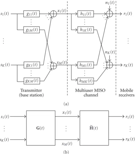
Figure1: Schematic block diagram of a prefiltering-based MISO UWB communication system.
assumed that maximum time dispersion isLTc. The channel fading coefficientαlcan be modeled as [22]
αl=blξl, (4)
wherebl = exp(jφn,l) is equiprobable to take on the value ±1. ξl = |αl| is the log-normal fading magnitude term. The average power of αl is represented by E{|αl|2} = Ω0exp(−ρl). Ω0 is a scalar for normalizing the power
contained in resolvable paths, and ρ is the power decay factor. To simplify the analysis, we assume that the channel parameters are quasistatic (slowly fading) such that they are essentially constant over observation interval.
3. Design of Transmitters and Receivers in
Prefiltered UWB MISO System
3.1. General Prefiltered UWB MISO System. As shown in
Figure 1 of the considered structure, there are M trans-mitting antennas equipped at the AP, and each RT has single antenna. Let hmk(t) =
L
l=0αmk,lδ(t−lTc) denote the CIR between the mth transmitting antenna and the kth RT, where αmk,l represents the fading coefficient of the lth path. In the proposed prefiltering scheme, a set of MK finite impulse response (FIR) prefilters with IRs gkm(t) =
P−1
p=0βkm,pδ(t − pTc) are inserted, respectively, between sk(t) and themth transmitting antenna. All users
are synchronously transmitted from the AP to all the RTs. Thereby, the transmitted waveform at themth antenna is
xm(t)= K
k=1
sk(t)∗gkm(t); m=1,. . .,M, (5)
where K is the number of RTs. Upon defining x(t) :=
[x1(t) x2(t) · · · xM(t)]T,s(t) :=[s1(t) s2(t) · · · sK(t)]T and theK×Mprefiltering matrix
G(t) := ⎡ ⎢ ⎢ ⎢ ⎢ ⎢ ⎢ ⎢ ⎣
g11(t) g12(t) · · · g1M(t) g21(t) g22(t) · · · g2M(t)
..
. . .. . .. ...
gK1(t) gK2(t) · · · gKM(t) ⎤ ⎥ ⎥ ⎥ ⎥ ⎥ ⎥ ⎥ ⎦
. (6)
We may reexpress (5) as a compact form:
x(t)=GT(t)∗s(t). (7)
The channel between the AP and arbitrary RT can be regarded as a MISO system. Hence, the received signal at the
kth RT can be formulated as
rk(t)= M
m=1
xm(t)∗hmk(t) +nk(t)
= M
m=1
⎛
⎝K
j=1
sj(t)∗gjm(t) ⎞
⎠∗hmk(t)
+nk(t); k=1,. . .,K
= K
j=1
sj(t)∗ M
m=1
gjm(t)∗hmk(t)
+nk(t), (8)
wherenk(t) is assumed to be zero-mean AWGN noise process with varianceσ2 (assume independent ofk for simplicity).
Similarly, letr(t) := [r1(t) r2(t) · · · rK(t)]T,n(t) := [n1(t) n2(t) · · · nK(t)]T and theM×K MISO mul-tiuser channel matrix
H(t) := ⎡ ⎢ ⎢ ⎢ ⎢ ⎢ ⎢ ⎢ ⎣
h11(t) h12(t) · · · h1K(t)
h21(t) h22(t) · · · h2K(t) ..
. . .. . .. ...
hM1(t) hM2(t) · · · hMK(t) ⎤ ⎥ ⎥ ⎥ ⎥ ⎥ ⎥ ⎥ ⎦
. (9)
We may reformulate (8) into a more convenient form:
r(t)=HT(t)∗x(t) +n(t)
=HT(t)∗GT(t)∗s(t) +n(t)
=G(t)∗H(t)T∗s(t) +n(t)
=HTeff(t)∗s(t) +n(t),
(10)
12 14 16 18 20 22 24 Number of transmitting antennas (M)
15 20 25 30 35 40 SINR (dB) LS scheme ZF scheme TR-MF scheme
Figure 2: SINR performance with respect to the number of transmitting antennas.
3.2. Zero-Forcing- (ZF-) Based Scheme. To completely re-move MUI, theMK prefilters should be designed to satisfy the following ZF criteria:
M
m=1
gjm(t)∗hmk(t)
= ⎧ ⎨ ⎩
0, j /=k,
ηkδ(t−LTc), j=k,
∀j,k=1,. . .,K, (11)
where LTc is the delay introduced to accommodate the multipath effect. ηk accounts for the power normalization factor designated for each RT so that the transmitter bit energy remains constant independent of the number of transmit antennas. In other words, ZF-based prefilters attempt to designG(t) such thatHeff(t) reduces to a diagonal
matrix
H(ZF)eff (t) :=G(ZF)(t)∗H(t)=
⎡ ⎢ ⎢ ⎢ ⎢ ⎣
η1 · · · 0
..
. . .. ...
0 · · · ηK ⎤ ⎥ ⎥ ⎥ ⎥
⎦δ(t−LTc).
(12)
Denoting the discrete-time version hmk(t) as a (L + 1) vector hmk := [αmk,0 αmk,1 · · · αmk,L]T, gjm(t) =
P−1
p=0 βjm,pδ(t − pTc) as a P vector gjm := [βjm,0 βjm,1 · · · βjm,P−1]T (Here, we assume the order of
the FIR prefilters being P), respectively, then the discrete-time counterparts of gjm(t) ∗ hmk(t) can be obtained as
Hmkgjm= ⎡ ⎢ ⎢ ⎢ ⎢ ⎢ ⎢ ⎢ ⎢ ⎢ ⎢ ⎢ ⎢ ⎢ ⎢ ⎢ ⎢ ⎢ ⎢ ⎢ ⎢ ⎢ ⎢ ⎣
αmk,0 0 · · · · 0
..
. αmk,0 . .. ... ...
αmk,L ... . .. ... ...
0 αmk,L . .. ... 0 ..
. 0 . .. ... αmk,0
..
. ... . .. ... ...
0 0 · · · 0 αmk,L ⎤ ⎥ ⎥ ⎥ ⎥ ⎥ ⎥ ⎥ ⎥ ⎥ ⎥ ⎥ ⎥ ⎥ ⎥ ⎥ ⎥ ⎥ ⎥ ⎥ ⎥ ⎥ ⎥ ⎦ ⎡ ⎢ ⎢ ⎢ ⎢ ⎢ ⎢ ⎢ ⎣
βjm,0
βjm,1
.. .
βjm,P−1
⎤ ⎥ ⎥ ⎥ ⎥ ⎥ ⎥ ⎥ ⎦ , (13)
whereHmk is a (L+P)×Pmatrix as defined in (13). Using (13), we may convert (11) into
Hkgj= ⎧ ⎨ ⎩
0L+P, j /=k,
ηkeL, j=k,
(14)
where eL denotes the Lth column vector of I(L+P). Hk := [H1k H2k · · · HMk] is a (L+P)×MPmatrix, andgj:= [gT
j1 gTj2 · · · gTjM] T
is aMPvector that incorporates the space-time IR of the jth user’s prefilters. Upon defining the K(L+P)×MPmatrixH:=[HT
1 HT2 · · · HTK] T
and the K(L+P) vector,e(Lk):=[0TL+P · · · eTL · · · 0TL+P]
T , we may reexpress (14) as
Hgk=ηke(Lk), (15)
wheree(Lk) denotes the (k(L+P)−P)th column vector of
IK(L+P).
IfK(L+P) ≤MP, which is up to our disposal (can be achieved by increasingMand/orP), we have infinitely many solutions since (15) is indeed an underdetermined system. The general solution includes a quiescent solution and a homogeneous solution that is chosen from the null (kernel) space ofH:
g(ZF)k =ηkHT
HHT−1e(k)
L +u; k=1,. . .,K, (16)
whereHu=0. It should be noted thatucan be regarded as the surplus part ofgksince it is useless for MUI suppression but only wastes transmission power. Thus, we letu = 0to minimize power consumption. Moreover, to guarantee the transmitted bit energy of thekth user to beEb,k = (Nf − 1)a2
kindependent of the prefilters and number of antennas, we chooseηksuch thatgk =1. It follows from (16) (after removingu)
gk2
=η2ke
(k)
L T
HHT−1e(Lk)
=η2
k
Hence,ηkis chosen as
η(ZF)k =
1
[HHT]−1(k(L+P)−P,k(L+P)−P). (18)
At the front end of each RT, chip-matched filtering (CMF) followed by chip-rate sampling, the discrete-time counterpart ofrk(t), can be obtained as
rk(n)=sk(n)∗ηkδ(n−L) +nk(n); k=1,. . .,K, (19)
where the interference has been removed by ZF prefiltering. After bit-by-bit stacking, we arrive at a sequence of NcNf vectors. The samples of CMF output within the ith bit interval at thekth RT are
rk(i)=ηkakdk(i)ck,L+nk(i), (20)
whereck,Lstands for anL-chips delayed version of thekth user’s TH code vectorck. The delay results from the criterion of (11). Since the MUI is completely removed, a simple correlation receiver can be employed that maximizes the averaged output SNR. The output signal (denoted asz(ZF)k ), averaged SNR (denoted asγ(ZF)k ), and bit-error-rate (BER) (denoted asPe(ZF)k ) can be obtained in order:
z(ZF)k (i)=cTk,Lrk(i)=ηkakdk(i)ck,L2+cTk,Lnk(i)
=ηk
Nf −1
akdk(i) +cTk,Lnk(i),
γ(kZF)= η2
ka2k
Nf −1
2
σ2N
f −1
= η
2
ka2k
Nf −1
σ2 ,
Pe(kZF)=Q
⎛ ⎜ ⎜ ⎝
ηkak
Nf −1
σ
⎞ ⎟ ⎟
⎠,
(21)
whereQ(x) :=1/√2π∞x exp(−(υ2/2))dυis a monotonically decreasing function with respect tox.
If on the other hand,K(L+P) > MP, or equivalently K > MP/(L+P), the ZF criteria are inapplicable since there is insufficient degrees of freedom to suppress the interference. In other words, (15) becomes an overdetermined system. It is generally impossible to obtain exact solution. By minimizing the least-squares (minimum distance) criterion [23], we can obtain thekth user’s prefilter as
g(LS)k =ηk
HTH−1HTe(Lk). (22)
Similar to the derivation in (17) and (18), the power normalization factor can be obtained as
η(LS)k =
1
H(HTH)−2HT(k(L+P)−P,k(L+P)−P) ,
k=1,. . .,K. (23)
Note that the LS solution can only “approximate” the ZF criteria. Therefore, the received signal at thekth RT should contain residual MUI:
rk(i)= K
j=1
ajdj(i)cj∗Hkgj+nk(i)
= K
j=1
ηjajdj(i)cjk+nk(i),
(24)
where cjk := cj ∗Hkgj. Applying the same correlator as ZF scheme, we can obtain the output averaged signal-to-interference-plus-noise ratio (SINR) as
γ(LS)k = η
2
ka2kρ2k
K
j=1,j /=ka2jη2jρ2j+σ2
Nf −1
, (25)
where ρj := cTk,Lcjk. With some manipulations, we can deduce the BER for the LS-based scheme:
PEk(LS)
=21−K
d1···dK∈{−1,+1} dk=1
Q
⎛ ⎜ ⎜ ⎜ ⎝
ηkakρk+
K
j=1,j /=kηjajρjdj
σNf −1
⎞ ⎟ ⎟ ⎟
⎠,
k=1,. . .,K. (26)
3.3. TR-MF-Based Scheme. In this scheme, a set of TR MFs with IRsgkm(t)=ηkmhmk(Td−t);k=1,. . .,K,m=1,. . .,M are placed at the transmitter as the prefilters, where Td denotes the delay spread (maximum dispersion) of the CIR. In the considered model,Td =LTc, thus we may rewrite the IR of the TR MF as
gkm(t)=ηkmhmk(Td−t)=ηkm L
l=0
αmk,L−lδ(t−lTc),
m=1,. . .,M, k=1,. . .,K. (27)
To guarantee that the energy per transmitted bit remains Eb,k=(Nf −1)a2kindependent of the prefilters and number of antennas, it is easy to deduce thatηkmshould be chosen as
ηkm= 1
MLl=0α2mk,L−l
=√ 1
Mhmk.
(28)
Apparently, the order of the prefilters in the TR-MF scheme is the same as the MISO CIR. Lethmk(Td−t) :=ηkmhmk(Td−t), then theK×Mprefiltering matrix for the TR MF scheme can be expressed as
G(MF)(t) := ⎡ ⎢ ⎢ ⎢ ⎢ ⎢ ⎢ ⎢ ⎢ ⎣
h11(Td−t) h12(Td−t) · · · h1M(Td−t)
h21(Td−t) h22(Td−t) · · · h2M(Td−t) ..
. . .. . .. ...
hK1(Td−t) hK2(Td−t) · · · hKM(Td−t) ⎤ ⎥ ⎥ ⎥ ⎥ ⎥ ⎥ ⎥ ⎥ ⎦
.
0 5 10 15 Desired user’s SNR
−5 0 5 10 15 20 25 30 35
SINR
(dB)
LS scheme (M=10) TR-MF scheme (M=10)
ZF scheme (M=20) TR-MF scheme (M=20) (a) SINR performance with respect to the desired user’s SNR.
0 5 10 15
Desired user’s SNR 10−10
10−8 10−6 10−4 10−2 100
BER
LS scheme (M=10) TR-MF scheme (M=10)
ZF scheme (M=20) TR-MF scheme (M=20) (b) BER performance with respect to the desired user’s SNR.
Figure3: System performance with respect to the desired user’s SNR.
The transmitted waveform at themth antenna is
xm(t)= K
k=1
sk(t)∗hmk(Td−t), m=1,. . .,M. (30)
Substituting (30) into (8), the received signal at thekth RT can be obtained as
rk(t)= M
m=1
xm(t)∗hmk(t) +nk(t)
= M
m=1
⎧ ⎨ ⎩ K
j=1
sj(t)∗hm j(Td−t) ⎫ ⎬
⎭∗hmk(t) +nk(t)
= M
m=1
"
sk(t)∗hmk(Td−t)∗hmk(t) #
+ M
m=1
K
j=1
j /=k "
sj(t)∗hm j(Td−t)∗hmk(t) #
+nk(t)
= M
m=1
{sk(t)∗Rmk(t)}
+ M
m=1
K
j=1
j /=k "
sj(t)∗Rm j,mk(t) #
+nk(t)
=sk(t)∗Rk(t) + K
j=1
j /=k "
sj(t)∗Rj,k(t) #
+nk(t)
(31)
whereRmk(t) :=hmk(Td−t)∗hmk(t) is the autocorrelation function ofhmk(t),Rm j,mk(t) :=hm j(Td−t)∗hmk(t) accounts
for the cross-correlation function betweenhmk(t) andhm j(t). Rk(t) :=
M
m=1Rmk(t), Rj,k(t) :=
M
m=1Rm j,mk(t). In what follows, the “effective” FIR channel matrix for the TR MF scheme yields
H(MF)eff (t) :=G(MF)(t)∗H(t)
= ⎡ ⎢ ⎢ ⎢ ⎢ ⎢ ⎢ ⎣
R1(t) R1,2(t) · · · R1,K(t) R2,1(t) R2(t) · · · R2,K(t)
..
. ... . .. ...
RK,1(t) RK,2(t) · · · RK(t) ⎤ ⎥ ⎥ ⎥ ⎥ ⎥ ⎥ ⎦
(32)
Denoting the discrete-time version of hmk(Td − t) =
L
l=0αmk,L−lδ(t − lTc) as an (L + 1) vector hmk := [αmk,L · · · αmk,1 αmk,0]T, then the discrete-time
coun-terparts of Rmk(t),Rm j,mk(t),Rk(t),Rj,k(t), respectively, can be formulated as
Rmk=ηkmhmk∗hmk
=ηkm ⎡ ⎢ ⎢ ⎢ ⎢ ⎢ ⎢ ⎢ ⎢ ⎢ ⎢ ⎢ ⎢ ⎢ ⎢ ⎢ ⎢ ⎢ ⎢ ⎢ ⎣
αmk,L 0 · · · · 0 ..
. αmk,L . .. ... ...
αmk,0 ... . .. ... ...
0 αmk,0 . .. ... 0
..
. 0 . .. ... αmk,L ..
. ... . .. ... ... 0 0 · · · 0 αmk,0
⎤ ⎥ ⎥ ⎥ ⎥ ⎥ ⎥ ⎥ ⎥ ⎥ ⎥ ⎥ ⎥ ⎥ ⎥ ⎥ ⎥ ⎥ ⎥ ⎥ ⎦
hmk
=ηkmHmkhmk,
where Hmk,Hm j are (2L + 1) × (L + 1) matrices.
Rmk,Rm j,mk,Rk,Rj,k all are vectors with size (2L+ 1)×1. Therefore, the magnitude ofhmk∗hmk will coherently add up at the central ((L+1)th) position of Rmk, in which the magnitude of the peak is Rmk(L+ 1) = ηkm
L
l=0α2mk,l = hmk2/
√
Mhmk = hmk/ √
M. On the other hand, the other terms of hm j ∗hmk will add up noncoherently and symmetrically distributed aboutRmk(L+ 1):
Rk= M
m=1 Rmk=
R1k R2k · · · RMk
1M,
Rj,k= M
m=1
Rm j,mk=
R1j,1k R2j,2k · · · RM j,Mk
1M.
(34)
It follows that the peak of Rk =
M
m=1Rmk is atRk(L+ 1) with the magnitude further be enhanced as Rk(L+ 1) = 1/√MMm=1hmk.
The samples of CMF output within theith bit interval at thekth RT can be expressed as
rk(i)=akdk(i)ck+ K
j=1
j /=k
ajdj(i)cjk+nk(i), k=1,. . .,K,
(35)
whereckrepresents the effective signature vector of thekth user. It arises from the CMF output’s chip-rate samples within a bit of the composite waveform,ck(t)∗Rk(t). It is evident thatckcan be formulated as
ck=
ck ck,1 · · · ck,2L
Rk=CkRk, (36)
where eachck,lstands for anl-chips delayed version of thekth user’s TH code.Ckis anNfNc×(2L+1) matrix. Similarly, we may formulate thejth (j /=k) user’s effective signature vector at thekth RT as
cjk =
cj cj,1 · · · cj,2L
Rj,k=CjRj,k. (37)
Since the peak ofRkis atRk(L+1), thereby, after convolv-ing withck(t), this will shift the positions of the desired user’s TH pulse train inck(t) by (L+ 1) chips. Therefore, to capture the energy of the desired user, we propose to design a simple correlation receiver to extract the energies at the positions of these peak components. Therefore, the weight vector of the proposed correlation receiver should be chosen asck,L. The output of the correlation receiver can be obtained as
zk(MF)(i)=cTk,Lrk(i)
=Rk(L+ 1)
Nf−1
akdk(i)
+cT k,L
K
j=1
j /=k
ajdj(i)cjk+cTk,Lnk(i).
(38)
Upon definingβj :=cTk,Lcjk, then the averaged SINR at the output of thekth user’s correlation receiver can be obtained as
γ(MF)k =
(Rk(L+ 1))2a2k
Nf −1
2
K
j=1,j /=ka2j$$$βj$$$
2
+σ2N
f−1
,
PE(MF)k =21−K d1...dK∈{−1,+1}
dk=1
Q
· ⎛ ⎜ ⎜ ⎜ ⎝
Rk(L+ 1)
Nf−1
ak+
K
j=1,j /=kβjajdj
σNf −1
⎞ ⎟ ⎟ ⎟
⎠,
k=1,. . .,K, (39)
4. Performance Evaluation
It is worthy to note that channel reciprocity is essential for using the prefiltering technique. Throughout the paper, we assume that channels are reciprocal between the AP and each RT; thereby, the MISO channel coefficients can be estimated by the AP by receiving sounding pulses (the sounding pulse should be made short enough to approachδ(t)) from each of the RT. Therefore, the transmitter has full knowledge of (or can perfectly estimate) the MISO channel’s information.
We first assume the average power of the path with index l = 0 to be normalized to be unity, that is,Ω0 = 1. The
log-normal fading amplitudeξlis generated byξl=exp(κl), where κl is a Gaussian random variable, κl ∼ N(μl,σl2). To satisfy the second moment of the log-normal random variable [24],E{ξl2} = exp(2(μl+σl2)) = Ω0exp(−ρl), we
have μl = −σl2−(ρl/2). We applyρ = 0.1,σl2 = 1 in all simulation examples (i.e.,κl∼N(−1−(l/20), 1)). For a fixed L, we generate 100 sets of channel parameters, {αmk,l}Ll=0.
Each data set is employed for simulation, and the result is obtained by taking average of the 100 independent trials.
Without loss of generality, we assume that user 1 is the desired user hereafter. Unless otherwise mentioned, we set the parameters Nf = 20, Nc = 35, L = 15, P = 20, K = 10, and each user’s SNR, which is defined as SNRk := 10 log (ak/σ)2, is set to be 15 dB throughout all the simulation examples.Figure 2presents the averaged SINR (γ1) with respect to the number of transmitting
antennasM, where the TR MF, LS (asM < K(L+P)/P), and ZF (as M ≥ K(L+P)/P) schemes are provided for comparison. It is verified for both the ZF- and LS-based prefilters that system performance improves asM increases (larger transmit diversity), nevertheless, the performance of the TR MF scheme is only slightly improved. This may result from the increase of interference power for larger M in the TR MF scheme. Figure 3 shows both the γ1 and BER
performance with respect to SNR1, where the performance
0 5 10 15 Near-far ratio (NFR)
8 10 12 14 16 18 20 22
SINR
(dB)
LS scheme TR-MF scheme
(a)
0 5 10 15
Near-far ratio (NFR) 10−6
10−5 10−4 10−3 10−2
BER
LS scheme TR-MF scheme
(b)
Figure4: System performance with respect to near-far ratio (NFR) for the TR MF and LS schemes. (a) SINR performance with respect to the near-far ratio (b) BER performance with respect to the near-far ratio.
2 4 6 8 10 12 14 16 18 20
Number of active users (K) 15
20 25 30 35 40 45
SINR
(dB)
ZF scheme LS scheme TR-MF scheme
Figure5: SINR performance with respect to the number of active users.
γ1increases (BER decreases) in accordance with SNR1. The
ZF scheme performs the best among the four curves since MUI has been completely removed. To measure the near-far resistance characteristics of the TR MF and the LS schemes (the ZF scheme is essentially near-far resistant), we first set all but one of the interferers’ (e.g., thekth user) amplitudes to be the same as the desired user, a1 = a2 = · · · =
ak−1=ak+1= · · ·aK, and define the near-far ratio (NFR) as the power ratio, (ak/a1)2(in dB). The performance in terms
of γ1 and BER with respect to NFR is depicted in Figures
4(a) and4(b), respectively, where we set M = 10. As we vary NFR from 0 to 15 dB, γ1 slowly decays, nevertheless,
it is still above 8 dB when NFR is as large as 15 dB. This demonstrates that both schemes are applicable in practical near-far environment.Figure 5 presentsγ1 with respect to
the number of active users, where we setM=20. The TR MF, ZF (asK≤MP/(L+P)), and LS (asK > MP/(L+P)) schemes are provided for comparison. As verified by the simulation results, the proposed ZF and LS based schemes are essentially robust to MUI, whereas the performance of TR MF scheme degrades asKincreases. Specifically,γ1of both TR MF and
ZF schemes coincide atK=1 (single user). This is due to the fact that the TR MF scheme is optimum in single-user case. In the final simulation example, we attempt to measureγ1of
the ZF and the LS schemes with respect to prefilter length, P. LetM = 20, L = 15 and K = 10, thus, LS scheme is implemented asP < KL/(M−K)=15, and ZF-based scheme is applied whenP ≥ 15. We can verify from Figure 6that increasing the temporal diversity effectively enhances system performance.
According to the above results, several remarks can be made.
(1) Though ZF-based scheme outperforms TR-MF-based scheme, nevertheless, the ZF scheme is only applicable whenK(L+P)≤MP. For example, ifP=
L, then the number of antenna must be at least twice as large as the number of active users (K≤M/2).
10 11 12 13 14 15 16 17 18 19 20 Prefilter length (P)
10 15 20 25 30 35
SINR
(dB)
LS scheme ZF scheme
Figure6: SINR performance of the ZF and LS schemes with respect to prefilter length.
prefiltering scheme, a decrease of this leads to per-formance degradation. As depicted in (18), several factors determine the value of ηk, for example, as K increases, ηk decreases as well. We have verified inFigure 5that largerK deteriorates system perfor-mance of the ZF-based prefiltering scheme.
5. Conclusions
Prefiltering-based multiuser interference suppression tech-niques have been applied in pulsed UWB system over MISO channel. The benefit of the proposed scheme is that it lessens the burden in signal processing of the RT receiver where a simplified correlation receiver is typically required. The simulation results have demonstrated that the proposed scheme can effectively mitigate near-far problem and suppress MUI. Though binary (antipodal) PAM scheme has been considered in this paper, extension to PPM scheme is without conceptual difficulty.
Acknowledgment
This research is supported by National Science Council (NSC) of Taiwan under Grant 97-2221-E-212-012.
References
[1] M. Z. Win and R. A. Scholtz, “Ultra-wide bandwidth time-hopping spread-spectrum impulse radio for wireless multiple-access communications,”IEEE Transactions on Communica-tions, vol. 48, no. 4, pp. 679–691, 2000.
[2] M. Z. Win, R. A. Scholtz, and M. A. Barnes, “Ultra-wide bandwidth signal propagation for indoor wireless multiple access communications,” inProceedings of IEEE International Conference on Communications (ICC ’97), vol. 1, pp. 56–60, Montreal, Canada, June 1997.
[3] M. Z. Win and R. A. Scholtz, “On the robustness of ultra-wide bandwidth signals in dense multipath environments,”IEEE Communications Letters, vol. 2, no. 2, pp. 51–53, 1998. [4] M. L. Welborn, “System considerations for ultra-wideband
wireless networks,” in Proceedings of the IEEE Radio and Wireless Conference (RAWCON ’01), pp. 5–8, Waltham, Mass, USA, August 2001.
[5] M. Z. Win and R. A. Scholtz, “Impulse radio: how it works,” IEEE Communications Letters, vol. 2, no. 2, pp. 36–39, 1998. [6] N. Boubaker and K. B. Letaief, “Ultra wideband DSSS for
multiple access communications using antipodal signaling,” inProceedings of IEEE International Conference on Communi-cations (ICC ’03), vol. 3, pp. 2197–2201, Anchorage, Alaska, USA, May 2003.
[7] F. R. Mireles, “Performance of ultrawideband SSMA using time hopping and M-ary PPM,”IEEE Journal on Selected Areas in Communications, vol. 19, no. 6, pp. 1186–1196, 2001. [8] L. Zhao and A. M. Haimovich, “Multiuser capacity of M-ary
PPM ultra-wideband communications,” inProceedings of the IEEE Conference on Ultra Wideband Systems and Technologies (UWBST ’02), pp. 175–179, Baltimore, Md, USA, May 2002. [9] R. C. Qiu, “A theory of time-reversed impulse
multiple-input multiple-output (MIMO) for ultra-wideband (UWB) communications,” in Proceedings of the IEEE International Conference on Ultra-Wideband (ICUWB ’06), pp. 587–592, Waltham, Mass, USA, September 2006.
[10] T. Strohmer, M. Emami, J. Hansen, G. Papanicolaou, and A. J. Paulraj, “Application of time-reversal with MMSE equalizer to UWB communications,” in Proceedings of IEEE Global Telecommunications Conference (GLOBECOM ’04), vol. 5, pp. 3123–3127, Dallas, Tex, USA, November-December 2004. [11] R. C. Qiu, C. Zhou, J. Q. Zhang, and N. Guo, “Channel
reciprocity and time-reversed propagation for ultra-wideband communications,” IEEE Antenna and Wireless Propagation Letters, vol. 5, no. 1, pp. 269–273, 2006.
[12] C. Zhou, N. Guo, and R. C. Qiu, “Experimental results on multiple-input single-output (MISO) time reversal for UWB systems in an office environment,” in Proceedings of IEEE Military Communications Conference (MILCOM ’06), Washington, DC, USA, October 2006.
[13] R. C. Qiu, B. Sadler, and Z. Hu, “Time reversed transmission with chirp signaling for UWB communications and its application in confined metal environments,” inProceedings of the IEEE International Conference on Ultra-Wideband (ICUWB ’07), pp. 276–281, Singapore, September 2007.
[14] S. Zhao and H. Liu, “Prerake diversity combining for pulsed UWB systems considering realistic channels with pulse overlapping and narrow-band interference,” in Proceedings of the IEEE Global Telecommunications Conference (GLOBE-COM ’05), pp. 3784–3788, St. Louis, Mo, USA, November-December 2005.
[15] Z. Tian and G. B. Giannakis, “Data-aided ML timing acquisition in ultra-wideband radios,” in Proceedings of the IEEE Conference on Ultra Wideband Systems and Technologies (UWBST ’03), pp. 142–146, Reston, Va, USA, November 2003. [16] L. Yang and G. B. Giannakis, “Low-complexity training for rapid timing acquisition in ultra-wideband communications,” in Proceedings of the IEEE Global Telecommunications Con-ference (GLOBECOM ’03), pp. 769–773, San Francisco, Calif, USA, December 2003.
Speech, and Signal Processing (ICASSP ’03), vol. 4, pp. 121–124, Hong Kong, April 2003.
[18] L. Yang and G. B. Giannakis, “Blind UWB timing with a dirty template,” inProceedings of the IEEE International Conference on Acoustics, Speech and Signal Processing (ICASSP ’04), vol. 4, pp. 509–512, Montreal, Canada, May 2004.
[19] H. T. Nguyen, I. Z. Kovacs, and P. C. F. Eggers, “A time reversal transmission approach for multiuser UWB communications,” IEEE Transactions on Antennas and Propagation, vol. 54, no. 11, pp. 3216–3224, 2006.
[20] A. F. Molisch, et al., “A comprehensive standardized model for ultrawideband propagation channels,”IEEE Transactions on Antennas and Propagation, vol. 54, no. 11, pp. 3151–3165, 2006.
[21] L. Yang and G. B. Giannakis, “Ultrawideband communica-tions: an idea whose time has come,”IEEE Signal Processing Magazine, pp. 26–54, November 2004.
[22] A. F. Molisch, J. R. Foerster, and M. Pendergrass, “Channel models for ultra-wideband personal area networks,” IEEE Wireless Communications, vol. 10, no. 6, pp. 14–21, 2003. [23] J. M. Mendel,Lessons in Estimation Theory for Signal
Process-ing, Communications, and Control, chapter 3, Prentice-Hall, Englewood Cliffs, NJ, USA, 1995.
[24] J. L. Devore,Probability and Statistics for Engineering and the Sciences, Duxbury Thomson Learning, 2000.