Debugging Package for
Motorola 68K CISC CPUs
User's Manual
(Part 2 of 2)
Notice
While reasonable efforts have been made to assure the accuracy of this document, Motorola, Inc. assumes no liability resulting from any omissions in this document, or from the use of the information obtained therein. Motorola reserves the right to revise this document and to make changes from time to time in the content hereof without obligation of Motorola to notify any person of such revision or changes.
No part of this material may be reproduced or copied in any tangible medium, or stored in a retrieval system, or transmitted in any form, or by any means, radio, electronic, mechanical, photocopying, recording or facsimile, or otherwise, without the prior written permission of Motorola, Inc.
It is possible that this publication may contain reference to, or information about Motorola products (machines and programs), programming, or services that are not announced in your country. Such references or information must not be construed to mean that Motorola intends to announce such Motorola products, programming, or services in your country.
Restricted Rights Legend
If the documentation contained herein is supplied, directly or indirectly, to the U.S. Government, the following notice shall apply unless otherwise agreed to in writing by Motorola, Inc.
Use, duplication, or disclosure by the Government is subject to restrictions as set forth in subparagraph (c)(1)(ii) of the Rights in Technical Data and Computer Software clause at DFARS 252.227-7013.
Motorola, Inc. Computer Group 2900 South Diablo Way
Preface
The Debugging Package for Motorola 68K CISC CPUs User's Manual provides general information for the onboard Þrmware package for all Motorola 68000 CISC CPU and MPU VMEmodule boards.
This document is bound in two parts. Part 1 (68KBUG1/D3) contains the Table of Contents and Chapters 1 through 3. Part 2 (68KBUG2/D3, this volume) contains Chapters 4 and 5, Appendices A through I, and the Index.
This manual is intended for anyone who wants to design OEM systems, supply additional capability to an existing compatible system, or work in a lab
environment for experimental purposes.
The following Þrmware packages and boards are covered in this manual:
The Þrmware packages are referred to as 16XBug in this manual. The boards are referred to as MVME16X.
This manual describes the debugger, the debugger command set, the one-line assembler/disassembler, and system calls. These functional elements are common to all Þrmware packages.
Installation, start-up, diagnostics tests, and environmental parameters are described in the diagnostic manuals for each of the Þrmware packages.
A basic knowledge of computers and digital logic is assumed.
Motorola and the Motorola symbol are registered trademarks of Motorola, Inc.
SYSTEM V/68 is a trademark of Motorola, Inc.
Timekeeper and Zeropower are trademarks of SGS-THOMSON Microelectronics.
MVME162 162Bug
MVME172 172Bug
MVME166 166Bug
MVME167 167Bug
MVME176 176Bug
Related Documentation
The following publications are applicable to Motorola 68K CISC CPU debugging packages and may provide additional helpful information. If not shipped with this product, they may be purchased by contacting your local Motorola sales ofÞce. Non-Motorola documents may be obtained from the sources listed following the table.
Document Title Motorola
Publication Number
M68040 Microprocessors User's Manual M68040UM/AD
M68060 Microprocessors User's Manual M68060UM/AD
MVME050 System Controller Module User's Manual MVME050/D
MVME162 ProgrammerÕs Reference Guide MVME162PG/D
MVME162FX ProgrammerÕs Reference Guide MVME162LXPG/D
MVME162LX ProgrammerÕs Reference Guide V162FXA/PG
MVME172 ProgrammerÕs Reference Guide VME172A/PG
Single Board Computers Programmer's Reference Guide VMESBCA1/PG and VMESBCA2/PG
162Bug Diagnostics UserÕs Manual V162DIAA/UM
167Bug Debugging Package UserÕs Manual MVME167BUG/D
172Bug Diagnostics UserÕs Manual V172DIAA/UM
177Bug Diagnostics User's Manual V177DIAA/UM
MVME320B VMEbus Disk Controller Module User's Manual MVME320B/D
MVME323 ESDI Disk Controller User's Manual MVME323/D
MVME327A VMEbus to SCSI Bus Adapter and MVME717 Transition Module User's Manual
MVME327A/D
MVME327A Firmware User's Manual MVME327AFW/D
MVME328 VMEbus Dual SCSI Host Adapter User's Manual MVME328/D MVME335 Serial and Parallel I/O Module User's Manual MVME335/D MVME350 Streaming Tape Controller VMEmodule User's Manual MVME350/D
Note Although not shown in the above list, each Motorola Computer Group manual publication number is suffixed with the revision level of the document, such as Ò2Ó (the second revision of a manual); a supplement bears the same number as a manual but has a suffix such as "2A1" (the first supplement to the second revision of the manual).
The following publications are available from the sources indicated.
ANSI Small Computer System Interface-2 (SCSI-2), Draft Document X3.131-198X, Revision 10c; Global Engineering Documents, P.O. Box 19539, Irvine, CA 92714.
Versatile Backplane Bus: VMEbus, ANSI/IEEE Std. 1014-1987, The Institute of Electrical and Electronics Engineers, Inc., 345 East 47th Street, New York, NY 10017 (VMEbus SpeciÞcation). This is also available as Microprocessor system bus for 1 to 4 byte data, IEC 821 BUS, Bureau Central de la Commission Electrotechnique Internationale; 3, rue de VarembŽ, Geneva, Switzerland.
Manual Terminology
Throughout this manual, a convention has been maintained whereby data and address parameters are preceded by a character which speciÞes the numeric format as follows:
Unless otherwise speciÞed, all address references are in hexadecimal throughout this manual.
An asterisk (*) following the signal name for signals which are level signiÞcant denotes that the signal is true or valid when the signal is low.
An asterisk (*) following the signal name for signals which are edge signiÞcant denotes that the actions initiated by that signal occur on high to low transition.
$ hexadecimal character
% binary number
In this manual, assertion and negation are used to specify forcing a signal to a particular state. In particular, assertion and assert refer to a signal that is active or true; negation and negate indicate a signal that is inactive or false. These terms are used independently of the voltage level (high or low) that they represent.
Data and address sizes are deÞned as follows:
❏ A byte is eight bits, numbered 0 through 7, with bit 0 being the
least significant.
❏ A word is 16 bits, numbered 0 through 15, with bit 0 being the
least significant.
❏ A longword is 32 bits, numbered 0 through 31, with bit 0 being
the least significant.
Conventions
The following conventions are used in this document:
bold is used for user input that you type just as it appears. Bold is also used for commands, options and arguments to commands, and names of programs, directories, and files.
italic is used for names of variables to which you assign values. Italic is also used for comments in screen displays and examples.
courier is used for system output (e.g., screen displays, reports), examples, and system prompts.
<RETURN> or <CR> represents the carriage return or Enter key.
The computer programs stored in the Read Only Memory of this device contain material copyrighted by Motorola Inc., 1995, and may be used only under a license such as those contained in MotorolaÕs software licenses.
The software described herein and the documentation appearing herein are furnished under a license agreement and may be used and/or disclosed only in accordance with the terms of the agreement.
The software and documentation are copyrighted materials. Making unauthorized copies is prohibited by law. No part of the software or documentation may be reproduced, transmitted, transcribed, stored in a retrieval system, or translated into any language or computer language, in any form or by any means without the prior written permission of Motorola, Inc.
Disclaimer of Warranty
Unless otherwise provided by written agreement with Motorola, Inc., the software and the documentation are provided on an Òas isÓ basis and without warranty. This disclaimer of warranty is in lieu of all warranties whether express, implied, or statutory, including implied warranties of merchantability or Þtness for any particular purpose.
!
WARNING This equipment generates, uses, and can radiate electro-magnetic energy. It may cause or be susceptible to electro-magnetic interference (EMI) if not installed and used in a cabinet with adequate EMI protection.
©Copyright Motorola 1997 All Rights Reserved
List of Tables
1
1
Using the One-Line
Assembler/Disassembler
Introduction
Included as part of the 16XBug firmware is an
assembler/disassembler function. The assembler is an interactive assembler/editor in which the source program is not saved. Each source line is translated into the proper MC68040 or MC68060 machine language code and is stored in memory on a line-by-line basis at the time of entry. In order to display an instruction, the machine code is disassembled, and the instruction mnemonic and operands are displayed. All valid MC68040 and MC68060
instructions are translated.
The 16XBug assembler is effectively a subset of the MC68040 and MC68060 resident structured assemblers. It has some limitations as compared with the resident assembler, such as not allowing line numbers and labels; however, it is a powerful tool for creating, modifying, and debugging MC68040 or MC68060 code.
MC68040 and MC68060 Assembly Language
The symbolic language used to code source programs for processing by the assembler is MC68040/MC68060 assembly language. This language is a collection of mnemonics representing:
❏ Operations
-MC68040/MC68060 machine-instruction operation codes -Directives (pseudo-ops)
Using the One-Line Assembler/Disassembler
1
Machine-Instruction Operation Codes
That part of the assembly language that provides the mnemonic machine- instruction operation codes for the MPU machine instructions is described in the appropriate microprocessor user's manual. See the Related Documentation section in the Preface. Refer to this manual for any question concerning operation codes.
Directives
Normally, assembly language can contain mnemonic directives which specify auxiliary actions to be performed by the assembler.
The 16XBug assembler recognizes only two directives called define constant (DC.W) and SYSCALL. These directives are used to define data within the program, and to make calls on 16XBug utilities. Refer to the sections on DC.W Define Constant Directive and on SYSCALL System Call Directive, respectively, for further details.
Comparison with MC68040 and MC68060 Assemblers
There are several major differences between the 16XBug assembler and the MC68040/MC68060 resident structured assembler. The resident assembler is a two-pass assembler that processes an entire program as a unit, while the 16XBug assembler processes each line of a program as an individual unit. Due mainly to this basic functional difference, the capabilities of the 16XBug assembler are more restricted:
❏ Label and line numbers are not used. Labels are used to
reference other lines and locations in a program. The one-line assembler has no knowledge of other lines and, therefore, cannot make the required association between a label and the label definition located on a separate line.
❏ Source lines are not saved. In order to read back a program
after it has been entered, the machine code is disassembled and then displayed as mnemonic and operands.
Source Program Coding
1
❏ No macro operation capability is included. ❏ No conditional assembly is used.
❏ Several symbols recognized by the resident assembler are not
included in the 16XBug assembler character set. These symbols include > and <. Three other symbols have multiple meanings to the resident assembler, depending on the context (refer to the section on Addressing Modes). These are:
Asterisk (*)
Multiplication operator or current value of the program counter.
Slash (/)
Division operator or delimiter in a register list. Ampersand (&)
Logical operator AND or a decimal number preÞx. Although functional differences exist between the two assemblers, the one-line assembler is a true subset of the resident assembler. The format and syntax used with the 16XBug assembler are acceptable to the resident assembler except as described above.
Source Program Coding
A source program is a sequence of source statements arranged in a logical way to perform a predetermined task. Each source
statement occupies a line and must be either an executable instruction, a DC.W directive, or a SYSCALL assembler directive. Each source statement follows a consistent source line format.
Using the One-Line Assembler/Disassembler
1
Operation Field
Because there is no label field, the operation field may begin in the first available column. It may also follow one or more spaces. Entries can consist of one of three categories:
1. Operation codes which correspond to the MC68040/MC68060 instruction set.
2. Define Constant directive: DC.W is recognized to define a constant in a word location.
3. System Call directive: SYSCALL is used to call 16XBug system utilities.
The size of the data field affected by an instruction is determined by the data size codes. Some instructions and directives can operate on more than one data size. For these operations, the data size code must be specified or a default size applicable to that instruction is assumed. The size code need not be specified if only one data size is permitted by the operation.
The data size code is specified by a period (.), appended to the operation field, am followed by B, W, or L, where:
B = Byte (8-bit data)
W = Word (the usual default size; 16-bit data)
L = Longword (32-bit data).
Source Program Coding
1
Examples (legal):
Example (illegal):
Operand Field
If present, the operand field follows the operation field and is separated from the operation field by at least one space. When two or more operand subfields appear within a statement, they must be separated by a comma.
In an instruction like ÒADD D1,D2Ó, the first subfield (D1) is called the source effective address field, and the second subfield (D2) is called the destination <EA> field. Thus, the contents on D1 are added to the contents of D2 and the result is saved in register D2.
In the instruction ÒMOVE D1,D2Ó the first subfield (D1) is the sending field and the second subfield (D2) is the receiving field.
In other words, for most two-operand instructions, the format Òopcode source,destinationÓ applies.
LEA (A0),A1 Longword size is assumed (.b, .w not allowed); this instruction loads the effective address of the Þrst operand into A1.
ADD.B (A0),D0 This instruction adds the byte whose address is
(A0) to the lowest order byte in D0.
ADD D1,D2 This instruction adds the low order word of D1 to the low order word of D2. (w is the default size code.)
ADD.L A3,D3 This instruction adds the entire 32-bit
(longword) contents of A3 to D3.
SUBA.B #5,A1 Illegal size speciÞcation (.b not allowed on
1
Disassembled Source Line
The disassembled source line may not look identical to the source line entered. The disassembler makes a decision on how it
interprets the numbers used. If the number is an offset from an address register, it is treated as a signed hexadecimal offset. Otherwise, it is treated as a straight unsigned hexadecimal.
For example,
MOVE.L #1234,5678
MOVE.L FFFFFFFC(A0),5678
disassembles to:
00003000 21FC0000 12345678 MOVE.L #$1234,($5678).W 00003008 21E8FFFC 5678 MOVE.L -$4(A0),($5678).W
Also, for some instructions, there are two valid mnemonics for the same opcode, or there is more than one assembly language
equivalent. The disassembler may choose a form different from the one originally entered. As examples:
1. BRA is returned for BT
2. DBF is returned for DBRA
Note The assembler recognizes two forms of mnemonics for two branch instructions. The BT form (branch
conditionally true) has the same opcode as the BRA instruction. Also, DBRA (decrement and branch always) and DBF (never true, decrement, and branch) mnemonics are different forms for the same
instruction. In each case, the assembler accepts both forms.
Mnemonics and Delimiters
1
❏ Decimal is a string of decimal digits (0 through 9) preceded by
an ampersand (&). For example: &12334
-&987654321
❏ Hexadecimal is a string of hexadecimal digits (0 through 9, A
through F) preceded by an optional dollar sign ($). For example:
$AFE5
One or more ASCII characters enclosed by apostrophes (' ') constitute an ASCII string. ASCII strings are right-justified and zero-filled (if necessary), whether stored or used as immediate operands.
Example
00005000 21FC0000 12345668 MOVE.L #$1234,($5678).W 00005008 0053 DC.W 'S'
0000500A 223C41424344 MOVE.L #'ABCD',D1 00005010 3536 DC.W '56'
The following register mnemonics are recognized/referenced by the assembler/ disassembler:
Pseudo-Registers
Main Processor Registers
R0-R7 User Offset Registers
PC Program Counter. Used only in forcing program counter-relative addressing.
1
Floating Point Unit Registers
Instruction and Data Cache Registers
MSP Master Stack Pointer (MC68040 only) ISP Interrupt Stack Pointer (MC68040 only) SSP Supervisor Stack Pointer (MC68060 only) VBR Vector Base Register
SFC Source Function Code Register DFC Destination Function Code Register D0-D7 Data Registers
A0-A7 Address Registers. For the MC68040, Address Register A7 represents the active System Stack Pointer, that is, one of USP, MSP, or ISP, as speciÞed by the M and S bits of the Status Register (SR). For the MC68060, Address Register A7 represents the active System Stack Pointer, that is, either USP or SSP, as speciÞed by the S bit in the Status Register.
FPCR Control Register FPSR Status Register
FPIAR Instruction Address Register FP0-FP7 Floating Point Data Registers
1
Memory Management Unit Registers
Character Set
The character set recognized by the 16XBug assembler is a subset of ASCII, and these are listed as follows:
❏ The letters A through Z (uppercase and lowercase) ❏ The integers 0 through 9
❏ Arithmetic operators: + - * / << >> ! & % ^ ❏ Parentheses ( )
❏ Characters used as special prefixes:
# (pound sign) specifies the immediate form of addressing. $ (dollar sign) specifies a hexadecimal number.
& (ampersand) specifies a decimal number. @ (commercial at sign) specifies an octal number. % (percent sign) specifies a binary number.
' (apostrophe) specifies an ASCII literal character string.
❏ Five separating characters:
MMUSR MMU Status Register (MC68040 only) URP User Root Pointer
SRP Supervisor Root Pointer TC Translation Control Register
1
/ (slash) - (dash)
❏ The character * (asterisk) indicates the current location.
Addressing Modes
Effective address modes, combined with operation codes, define the particular function to be performed by a given instruction. Effective addressing and data organization are described in detail in the section on Data Organization and Addressing Capabilities, of the appropriate microprocessor user's manual. See the Related
Documentation section in the Preface.
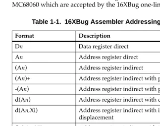
Table 4-1 summarizes the addressing modes of the MC68040 and MC68060 which are accepted by the 16XBug one-line assembler.
Table 1-1. 16XBug Assembler Addressing Modes
Format Description
Dn Data register direct An Address register direct (An) Address register indirect
(An)+ Address register indirect with post-increment -(An) Address register indirect with pre-decrement d(An) Address register indirect with displacement d(An,Xi) Address register indirect with index, 8-bit
displacement
(bd,An,Xi) Address register indirect with index, base displacement.
([bd,An],Xi,od) Address register memory indirect post-indexed
([bd,An,Xi],od) Address register memory indirect pre-indexed
1
You may use an expression in any numeric field of these addressing modes. The assembler has a built-in expression evaluator. It supports the following operand types:
Allowed operators are:
address(PC,Xi) Program counter indirect with index, 8-bit displacement
(address,PC,Xi) Program counter indirect with index, base displacement
([address,PC],Xi,od) Program counter memory indirect post-indexed
([address,PC,Xi],od) Program counter memory indirect pre-indexed
(xxxx).W Absolute word address (xxxx).L Absolute long address #xxxx Immediate data
Binary numbers (%10 ) Octal numbers (@765..0) Decimal numbers (&987..0) Hexadecimal numbers ($FED..0) String literals ('CHAR' ) Offset registers (R0 - R7) Program counter (*)
Addition + (plus)
Table 1-1. 16XBug Assembler Addressing Modes
1
The order of evaluation is strictly left to right with no precedence granted to some operators over others. The only exception to this is when you force the order of precedence through the use of parentheses.
Possible points of confusion:
❏ Keep in mind that where a number is intended and it could
be confused with a register, it must be differentiated in some way.
❏ With the use of " * " to represent both multiply and program counter, how does the assembler know when to use which definition?
For parsing algebraic expressions, the order of parsing is
operand operator operand operator ... with a possible left or right parenthesis.
Given the above order, the assembler can distinguish by placement which definition to use. For example:
*** Means PC * PC
Shift left << (left angle brackets) Shift right >> (right angle brackets) Bitwise OR ! (exclamation mark) Bitwise AND & (ampersand) Modulus % (percent) Exponentiate ^ (circumßex) One's Complement ~ (tilde)
CLR D0 This means CLR.W register D0. CLR $D0
On the other hand, these all mean CLR.W memory location $D0.
CLR 0D0
CLR +D0
1
2** Means 2 * PC
*&&16 Means PC AND &16
When specifying operands, you may skip or omit entries with the following addressing modes.
❏ Address register indirect with index, base displacement. ❏ Address register memory indirect post-indexed.
❏ Address register memory indirect pre-indexed.
❏ Program counter indirect with index, base displacement. ❏ Program counter memory indirect post-indexed.
❏ Program counter memory indirect pre-indexed.
For modes address register/program counter indirect with index, base displacement, the rules for omission/skipping are as follows:
❏ You may terminate the operand at any time by specifying " )".
For example: CLR ( )
or
CLR (,,)
is equivalent to:
CLR (0.N,ZA0,ZD0.W*1)
❏ You may skip a field by " stepping past" it with a comma. For
example:
CLR (D7)
is equivalent to:
CLR ($D7,ZA0,ZD0.W*1)
but
1
❏ If you do not specify the base register, the default " ZA0" is
forced.
❏ If you do not specify the index register, the default "
ZD0.W*1" is forced.
❏ Any unspecified displacements are defaulted to " 0.N". ❏ The rules for parsing the memory indirect addressing modes
are the same as above with the following additions.
❏ The subfield that begins with "[" must be terminated with a
matching "]".
❏ If the text given is insufficient to distinguish between the
preindexed or postindexed addressing modes, the default is the preindexed form.
DC.W Define Constant Directive
The format for the DC.W directive is:
DC.W operand
The function of this directive is to define a constant in memory. The DC.W directive can have only one operand (16-bit value) which can contain the actual value (decimal, hexadecimal, or ASCII).
Alternatively, the operand can be an expression which can be assigned a numeric value by the assembler. The constant is aligned on a word boundary as word .w is specified. An ASCII string is recognized when characters are enclosed inside single quotes (' '). Each character (seven bits) is assigned to a byte of memory, with the eighth bit (MSB) always equal to zero. If only one byte is entered, the byte is right justified. A maximum of two ASCII characters may be entered for each DC.W directive.
Examples are:
1
00010028 5443 DC.W 'TB'+1 Expression0001002A 0043 DC.W 'C' ASCII character is
right justified
SYSCALL System Call Directive
The function of this directive is to aid you in making the TRAP #15 calls to 16XBug functions as defined in Chapter 5. The format for this directive is:
SYSCALL function-name
For example, the following two pieces of code produce identical results.
TRAP #$F DC.W 0
or
SYSCALL .INCHR
Refer to Chapter 5, System Calls, for a complete listing of all the functions provided.
Entering and Modifying Source Programs
User programs are entered into the memory using the one-line assembler/ disassembler. The program is entered in assembly language statements on a line-by-line basis. The source code is not saved as it is converted immediately to machine code upon entry. This imposes several restrictions on the type of source line that can be entered.Symbols and labels, other than the defined instruction mnemonics, are not allowed. The assembler has no means to store the
1
Also, editing is accomplished by retyping the entire new source line. Lines can be added or deleted by moving a block of memory data to free up or delete the appropriate number of locations (refer to the Block Move (BM) command).
Invoking the Assembler/Disassembler
The assembler/disassembler is invoked using the ;DI option of the Memory Modify (MM) and Memory Display (MD) commands:
MMaddress;DI or
ASaddress
where <CR> sequences to next instruction and .<CR> exits command
and
MD[S] address[:count | address];DI or
DSaddress[:count | address]
1
Entering a Source Line
A new source line is entered immediately following the
disassembled line, using the format discussed in the section on Source Line Format.
167-Bug>MM 10000;DI
00010000 2600 MOVE.L D0,D3 ? ADDQ.L #1,A3 When the carriage return is entered terminating the line, the old source line is erased from the terminal screen, the new line is assembled and displayed, and the next instruction in memory is disassembled and displayed.
167Bug>MM 10000;DI
00010000 528B ADDQ.L #1,A3
00010002 4282 CLR.L D2 ?(CR)
If a hardcopy terminal is being used, port 0 should be reconfigured for hardcopy mode for proper operation (refer to the PF command.) In this case, the above example would look as follows:
167Bug>MM 10000;DI
00010000 2600 MOVE.L D0,D3 ? ADDQ.L #1,A3 00010000 528B ADDQ.L #1,A3
00010002 4282 CLR.L D2 ? <CR>
Another program line can now be entered. Program entry
continues in like manner until all lines have been entered. A period is used to exit the MM or AS command.
If an error is encountered during assembly of the new line, the assembler displays the line unassembled with a "^" under the field suspected of causing the error and an error message is displayed. The location being accessed is redisplayed.
167Bug>MM 10000;DI
2
Introduction
This chapter describes the 16XBug TRAP #15 handler, which allows system calls from user programs. The system calls can be used to access selected functional routines contained within 16XBug, including input and output routines. TRAP #15 may also be used to transfer control to 16XBug at the end of a user program (refer to the .RETURN function in this chapter).
In the descriptions of some input and output functions, reference is made to the "default input port" or the "default output port". After power-up or reset, the default input and output port is initialized to be port 0 (the MVME16X debug port). The defaults may be changed, however, using the .REDIR_I and .REDIR_O functions, as described in this chapter.
Invoking System Calls through TRAP #15
To invoke a system call from a user program, simply insert a TRAP #15 instruction into the source program. The code corresponding to the particular system routine is specified in the word following the TRAP opcode, as shown in the following example.
Format in your program:
TRAP #15 System call to 16XBug.
DC.W $xxxx Routine being requested (xxxx = code). In some of the examples shown in the following descriptions, a
2
SYSCALL MACRO TRAP #15
DC.W \1
ENDM
Using the SYSCALL macro, the system call would appear in your program as follows:
SYSCALL routine name
It is, of course, necessary to create an equate file with the routine names equated to their respective codes.
When using the 16XBug one-line assembler/disassembler, the
SYSCALL macro and the equates are predefined. Simply write in
SYSCALL followed by a space and the function, then carriage return.
Example
167-Bug>M 03000;DI
00003000 00000000 ORI.B #$0,D0? SYSCALL .OUTLN 00003000 4E4F0022 SYSCALL .OUTLN
00003004 00000000 ORI.B #$0,D0? . 167Bug>
String Formats for I/O
Within the context of the TRAP #15 handler there are two formats for strings:
A line is defined as a string followed by a carriage return and a line feed: <CR><LF>.
Pointer/Pointer Format The string is deÞned by a pointer to the Þrst character and a pointer to the last character + 1.
2
System Call Routines
On entry to Firmware System Call routines, the machine state is saved so that a subsequent ABORT or BREAK condition allows you to resume if you wish.
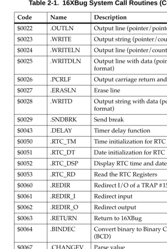
The TRAP #15 functions are summarized in Table 5-1. Refer to the write-ups on the utilities for specific use information.
Table 2-1. 16XBug System Call Routines
Code Name Description
$0000 .INCHR Input character $0001 .INSTAT Input serial port status
$0002 .INLN Input line (pointer/pointer format) $0003 .READSTR Input string (pointer/count format) $0004 .READLN Input line (pointer/count format) $0005 .CHKBRK Check for break
$0010 .DSKRD Disk read $0011 .DSKWR Disk write $0012 .DSKCFIG Disk conÞgure $0014 .DSKFMT Disk format $0015 .DSKCTRL Disk control
$0018 .NETRD Read/get Þles from host $0019 .NETWR Write/send Þles to host $001A .NETCFIG ConÞgure network parameters $001B .NETFOPN Open Þle for reading
$001C .NETFRD Retrieve speciÞed Þle blocks
2
$0022 .OUTLN Output line (pointer/pointer format) $0023 .WRITE Output string (pointer/count format) $0024 .WRITELN Output line (pointer/count format) $0025 .WRITDLN Output line with data (pointer/count
format)
$0026 .PCRLF Output carriage return and line feed $0027 .ERASLN Erase line
$0028 .WRITD Output string with data (pointer/count format)
$0029 .SNDBRK Send break
$0043 .DELAY Timer delay function $0050 .RTC_TM Time initialization for RTC $0051 .RTC_DT Date initialization for RTC $0052 .RTC_DSP Display RTC time and date $0053 .RTC_RD Read the RTC Registers
$0060 .REDIR Redirect I/O of a TRAP #15 function $0061 .REDIR_I Redirect input
$0062 .REDIR_O Redirect output $0063 .RETURN Return to 16XBug
$0064 .BINDEC Convert binary to Binary Coded Decimal (BCD)
$0067 .CHANGEV Parse value
$0068 .STRCMP Compare two strings (pointer/count format)
$0069 .MULU32 Multiply two 32-bit unsigned integers $006A .DIVU32 Divide two 32-bit unsigned integers $006B .CHK_SUM Generate checksum
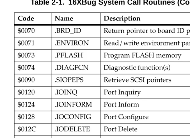
Table 2-1. 16XBug System Call Routines (Continued)
2
Note In most examples of commands and displays given in this manual, 167Bug is used. However, the commands, displays, and system calls apply to all 68K CISC debugging packages, unless otherwise noted.
$0070 .BRD_ID Return pointer to board ID packet $0071 .ENVIRON Read/write environment parameters $0073 .PFLASH Program FLASH memory
$0074 .DIAGFCN Diagnostic function(s) $0090 .SIOPEPS Retrieve SCSI pointers $0120 .IOINQ Port Inquiry
$0124 .IOINFORM Port Inform $0128 .IOCONFIG Port ConÞgure $012C .IODELETE Port Delete
$0130 .SYMBOLTA Attach Symbol Table $0131 .SYMBOLTD Detach Symbol Table $0140 .ACFSTAT ACFAIL Status Inquiry
Table 2-1. 16XBug System Call Routines (Continued)
2
.INCHR Function
Name
INCHR - Input character routine
Code
$0000
Description
.INCHR reads a character from the default input port. The character is returned in the stack.
Entry Conditions
Exit Conditions Different from Entry
Example
SUBQ.L #2,A7 Allocate space for result. SYSCALL .INCHR Call .INCHR.
MOVE.B (A7)+,D0 Load character in D0.
SP ==> Space for character. byte
Word Þll. byte
SP ==> Character. byte
2
.INSTAT Function
Name
.INSTAT - Input serial port status
Code
$0001
Description
.INSTAT is used to see if there are characters in the default input port buffer. The condition codes are set to indicate the result of the operation.
Entry Conditions
No arguments or stack allocation required.
Exit Conditions Different from Entry
Z(ero) = 1 if the receiver buffer is empty.
Example
LOOP SYSCALL .INSTAT Any characters? BEQ.S EMPTY No, branch.
SUBQ.L #2,A7 Yes, then read them in buffer. SYSCALL .INCHR
MOVE.B (A7)+,(A0)+
2
.INLN Function
Name
.INLN - Input line routine
Code
$0002
Description
.INLN is used to read a line from the default input port. The buffer size should be at least 256 bytes.
Entry Conditions
Exit Conditions Different from Entry
Example
If A0 contains the address where the string is to go;
SUBQ.L #4,A7 Allocate space for result.
PEA (A0) Push pointer to destination
TRAP #15 (May also invoke by SYSCALL
DC.W 2 macro SYSCALL .INLN.)
MOVE.L (A7)+,A1 Retrieve address of last character + 1.
Note A line is a string of characters terminated by <CR>. The maximum allowed size is 254 characters. The
terminating <CR> is not considered part of the string, but it is returned in the buffer, that is, the returned pointer points to it. Control character processing as described in the section on Terminal Input/Output
SP ==> Address of string buffer. longword
SP ==> Address of last character in the string + 1.
2
.READSTR Function
Name
.READSTR - Read string into variable-length buffer
Code
$0003
Description
READSTR is used to read a string of characters from the default input port into a buffer. On entry, the first byte in the buffer indicates the maximum number of characters that can be placed in the buffer. The buffer size should at least be equal to that
number+2. The maximum number of characters that can be placed in a buffer is 254 characters. On exit, the count byte indicates the number of characters in the buffer. Input terminates when a <CR>
is received. A null character appears in the buffer, although it is not included in the string count. All printable characters are echoed to the default output port. The <CR> is not echoed. Some control character processing is done:
^G Bell Echoed.
^X Cancel line Line is erased.
^H Backspace Last character is erased.
<DEL> Same as backspace Last character is erased.
<LF> Line Feed Echoed.
2
Entry Conditions
Exit Conditions Different from Entry
The count byte contains the number of bytes in the buffer.
Example
If A0 contains the string buffer address;
MOVE.B #75,(A0) Set maximum string size.
PEA (A0) Push buffer address.
TRAP #15 (May also invoke by SYSCALL
DC.W 3 macro SYSCALL .READSTR.)
MOVE.B (A0),D0 Read actual string size.
Note This routine allows the caller to dictate the maximum length of input to be less than 254 characters. If more characters are entered, then the buffer input is
truncated. Control character processing as described in the section on Terminal Input/Output Control is in effect.
SP ==> Address of input buffer. longword
2
.READLN Function
Name
.READLN - Read line to fixed-length buffer
Code
$0004
Description
.READLN is used to read a string of characters from the default input port. Characters are echoed to the default output port. A string consists of a count byte followed by the characters read from the input. The count byte indicates the number of characters in the input string, excluding <CR><LF>. A string may be up to 254 characters.
Entry Conditions
Exit Conditions Different from Entry
The first byte in the buffer indicates the string length.
Example
If A0 points to a 256 byte buffer.
PEA (A0) Long buffer address and read a
SYSCALL .READLN line from default input port.
Note The caller must allocate 256 bytes for a buffer. Input may be up to 254 characters. <CR><LF> is sent to
SP ==> Address of input buffer. longword
2
.CHKBRK Function
Name
.CHKBRK - Check for break
Code
$0005
Description
.CHKBRK returns "zero" status in the condition code register if break status is detected at the default input port.
Entry Conditions
No arguments or stack allocation required.
Exit Conditions Different from Entry
Z flag set in CCR if break status is detected.
Example
SYSCALL .CHKBRK
2
.DSKRD, .DSKWR Functions
Name
.DSKRD - Disk read function .DSKWR - Disk write function
Code
$0010 $0011
Description
These functions are used to read and write blocks of data from/to the specified disk or tape device. Information about the data transfer is passed in a command packet which has been built somewhere in memory. (Your program must first manually prepare the packet.) The address of the packet is passed as an argument to the function. The same command packet format is used for .DSKRD and .DSKWR. It is eight words in length and is arranged as follows:
Field descriptions:
F E D C B A 9 8 7 6 5 4 3 2 1 0
$00 Controller LUN Device LUN
$02 Status Word
$04
Memory Address
Most Significant Word
$06 Least Significant Word
$08 Block Number (Disk) Most Significant Word
or
$0A File Number (Tape) Least Significant Word
$0C Number of Blocks
$0E Flag Byte Address Modifier
2
Entry Conditions
Exit Conditions Different from Entry
Status word of command packet is updated.
Data is written into memory as a result of .DSKRD function. Data is written to disk as a result of .DSKWR function. Z(ero) = Set to 1 if no errors.
Example
If A0, A1 point to packets formatted as specified above.
PEA (A0)
SYSCALL .DSKRD Read from disk. BNE ERROR Branch if error.
PEA (A1)
SYSCALL .DSKWR Write to disk. BNE ERROR Branch if error. .
. .
ERROR xxxxx xxx Handle error.
0 Reads or writes are done until the speciÞed block count is exhausted.
1 Reads are done until the count is exhausted or until a Þlemark is found. Writes are terminated with a Þlemark.
Address ModiÞer VMEbus address modiÞer to use while transferring data. If zero, a default value is selected by the bug. If nonzero, the speciÞed value is used..
SP ==> Address of command packet. longword
2
.DSKCFIG Function
Name
.DSKCFIG - Disk configure function
Code
$0012
Description
This function allows you to change the configuration of the specified device. It effectively performs an "IOT under program control". All the required parameters are passed in a command packet which has been built somewhere in memory. The address of the packet is passed as an argument to the function. This function is provided for use in special applications, because .DSKCFIG is invoked automatically the first time that a device is accessed by
.DSKRD, .DSKWR, or .DSKFMT. The packet format is as follows:
Field descriptions:
F E D C B A 9 8 7 6 5 4 3 2 1 0
$00 Controller LUN Device LUN
$02 Status Word
$04
Memory Address
Most Significant Word
$06 Least Significant Word
$08 0
$0A 0
$0C 0
$0E Flag Byte Address Modifier
Controller LUN Logical Unit Number (LUN) of controller to use. Device LUN Logical Unit Number of device to use.
2
The Device Descriptor Packet format is as follows:
Field descriptions:
Memory Address Contains a pointer to a Device Descriptor Packet that contains the conÞguration information to be
changed.
Flag Byte This Þeld contains additional information. Bit 0 is used to allow reading/writing the conÞguration of the speciÞed device. It is interpreted as follows:
0 You can change (write) the conÞguration. 1 You can view (read) the conÞguration.
Address ModiÞer VMEbus address modiÞer to use while transferring data. If zero, a default value is selected by the bug. If nonzero, the speciÞed value is used.
F E D C B A 9 8 7 6 5 4 3 2 1 0
$00 Controller LUN Device LUN
$02 0
$04
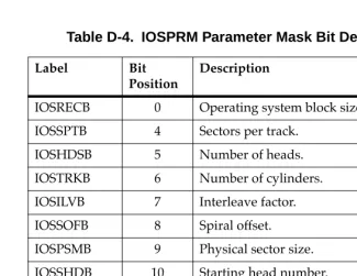
Parameters Mask
Upper (Most Significant) Word
$06 Lower (Least Significant) Word
$08
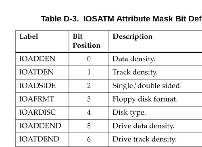
Attributes Mask
Upper (Most Significant) Word
$0A Lower (Least Significant) Word
$0C
Attributes Flags
Upper (Most Significant) Word
$0E Lower (Least Significant) Word
$10
2
List notes:
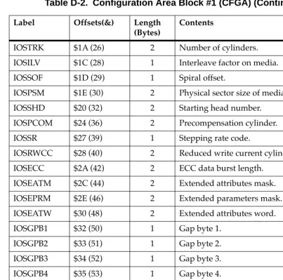
P_DSH* $18 1 IOSSHD Starting head P_DNH $19 1 IOSHDS Number of heads P_DNCYL $1A 2 IOSTRK Number of cylinders P_DPCYL $1C 2 IOSPCOM Precompensation cylinder P_DRWCYL $1E 2 IOSRWCC Reduced write current
cylinder
P_DECCB $20 2 IOSECC ECC data burst length P_DGAP1 $22 1 IOSGPB1 Gap 1 size
P_DGAP2 $23 1 IOSGPB2 Gap 2 size P_DGAP3 $24 1 IOSGPB3 Gap 3 size P_DGAP4 $25 1 IOSGPB4 Gap 4 size
P_DSSC $26 1 IOSSSC Spare sectors count P_DRUNIT $27 1 IOSRUNIT Reserved area units
P_DRCALT $28 2 IOSRSVC1 Reserved count for alternates P_DRCCTR $2A 2 IOSRSVC2 Reserved count for controller
P_DDS This Þeld is for internal use only, and does not have an equivalent CFGA Þeld. It should be set to 0. P_DSS This is a one byte encoded Þeld, whereas the
IOSPSM Þeld is a two byte unencoded Þeld containing the actual number of bytes per sector. The P_DSS Þeld is encoded as follows:
$00 128 bytes $01 256 bytes
Field Name Offset (Bytes)
Length (Bytes)
CFGA
2
Entry Conditions
Exit Conditions Different from Entry
Status word of command packet is updated. The device configuration is changed.
Z(ero) = Set to 1 if no errors.
Example
If A0 points to packet formatted as specified above.:
PEA.L (A0) Load command packet. SYSCALL .DSKCFIG Reconfigure device. BNE ERROR Branch if error. :
.
ERROR xxxxx xxx Handle error.
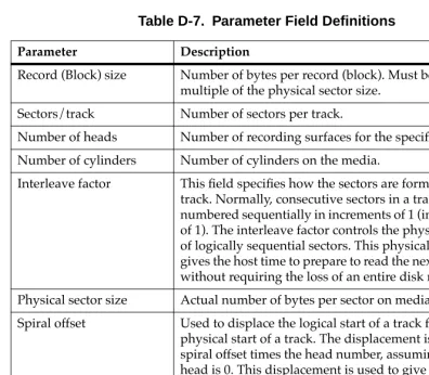
P_DBS This is a one byte encoded field, whereas the IOSREC field is a two byte unencoded field containing the actual number of bytes per record (block). The P_DBS field is encoded as follows
$00 128 bytes $01 256 bytes $02 512 bytes $03 1024 bytes
$04 - $FF Reserved encodings
P_DST This is a two byte Þeld, whereas the IOSSPT Þeld is one byte.
P_DSH This is a one byte Þeld, whereas the IOSSHD Þeld is two bytes. This Þeld is equivalent to the lower byte of IOSSHD.
SP ==> Address of command packet. longword
2
.DSKFMT Function
Name
.DSKFMT - Disk format function
Code
$0014
Description
This function allows you to send a format command to the specified device. The parameters required for the command are passed in a command packet which has been built somewhere in memory. The address of the packet is passed as an argument to the function. The packet format is as follows:
Field descriptions:
F E D C B A 9 8 7 6 5 4 3 2 1 0
$00 Controller LUN Device LUN
$02 Status Half-Word
$04
Memory Address
Most Significant Word
$06 Least Significant Word
$08
Disk Block Number
Most Significant Word
$0A Least Significant Word
$0C 0
$0E Flag Byte Address Modifier
Controller LUN Logical Unit Number (LUN) of controller to use.
Device LUN Logical Unit Number of device to use. Status Word This status word reßects the result of the
operation. It is zero if the command completed without errors. Refer to Appendix F for
2
Entry Conditions
Exit Conditions Different from Entry
Status word of command packet is updated.
Example
If A0 points to packet formatted as specified above.
PEA.L (A0) Load command packet. SYSCALL .DSKFMT Format device.
BNE ERROR Branch if error. .
.
.
ERROR xxxxx xxx Handle error. xxxxx xxx
1 The grown defect list is ignored when formatting.
Note that the previous ßag byte operations are still true; the operation settings are OR'd together.
Address ModiÞer VMEbus address modiÞer to use while transferring data. If zero, a default value is selected by the bug. If nonzero, the speciÞed value is used.
SP ==> Address of command packet. longword
2
.DSKCTRL Function
Name
.DSKCTRL - Disk control function
Code
$0015
Description
This function is used to implement any special device control functions that cannot be accommodated easily with any of the other disk functions. At the present, the only defined function is SEND packet, which allows you to send a packet in the specified format of the controller. The required parameters are passed in a command packet which has been built somewhere in memory. The address of the packet is passed as an argument to the function. The packet format is as follows:
Field descriptions:
F E D C B A 9 8 7 6 5 4 3 2 1 0
$00 Controller LUN Device LUN
$02 Status Word
$04
Memory Address
Most Significant Word
$06 Least Significant Word
$08 0
$0A 0
$0C 0
$0E 0 Address Modifier
Controller LUN Logical Unit Number (LUN) of controller to use.
Device LUN Logical Unit Number of device to use. Status Word This status word reßects the result of the
operation. It is zero if the command completed without errors. Refer to Appendix F for
2
Entry Conditions
Exit Conditions Different from Entry
Status word of command packet is updated.
Additional side effects depend on the packet sent to the controller. Z(ero) = Set to 1 if no errors.
Example
If A1 points to a packet formatted as specified above;
PEA.L (A1) Load command packet. SYSCALL .DSKCTRL Invoke control function. BNE ERROR Branch if error.
. . .
ERROR xxxxx xxx Handle error. xxxxx xxx
Memory Address Contains a pointer to the controller packet to send. Note that the controller packet to send (as opposed to the command packet) is controller and device dependent. Information about this packet should be found in the user's manual for the controller and device being accessed.
Address ModiÞer VMEbus address modiÞer to use while transferring data. If zero, a default value is selected by the bug. If nonzero, the speciÞed value is used.
SP ==> Address of command packet. longword
2
ExampleSee Appendix I. Boot Filename String
This Þeld is the string of the name of the Þle to load/store. On a write the Þle must exist on the host system and also be writable (write
2
System Call Routines
.NETFOPN Function
Name
.NETFOPN - Open file for reading
Code
$001B
Description
These function allows the user to open a file for reading. The firmware basically transmits a TFTP Read Request for the specified file and returns to the user. It is your responsibility to retrieve the forthcoming file blocks; youwould use the .NETFRD system call to do this. You must also perform the file block retrievals in a timely fashion, else the TFTP server will time-out.
Information about the file open/request is passed in a command packet which has been built in memory. (The user program must first manually prepare the packet.) The address of the packet is passed as an argument to the function. All packets must be longword aligned.
The packet structure, NFILEOPEN, is listed in the "C" header file in Appendix I. Its format is shown below:
Field descriptions:
F E D C B A 9 8 7 6 5 4 3 2 1 0
$00 Controller LUN Device LUN
$02 Status Word
$04
$42
Filename String $40(&64) Bytes
2
Example
See Appendix I.
Status Word This status word reßects the result of the operation. It is zero if the command completed without errors. Refer to Appendix H for meanings of returned error codes.
Filename String This Þeld is the string of the name of the Þle to load. The Þlename string must be null
2
.NETFRD Function
Name
.NETFRD - Retrieve specified file blocks
Code
$001C
Description
This function allows you to retrieve the specified file blocks. You would use this function multiple times to retrieve the entire file. Prior to using this function a .NETFOPN system call must have been performed. For each file block retrieved the firmware will transmit a TFTP ACK packet to acknowledge the receipt of data. The end of data will be signified when the number o f bytes transferred is smaller than the block size. The block size is set at 512 bytes (TFTP convention). For each .NETFRD system call
performed, you must update (increment by one) the block number field of the command packet. Initially the block number is one.
Information about the file block is passed in a command packet which has been built in memory. (The user program must first manually prepare the packet.) The address of the packet is passed as an argument to the function. All packets must be longword aligned. The packet structure, NFILEREAD, is listed in the "C" header file in Appendix I. Its format is shown below:
F E D C B A 9 8 7 6 5 4 3 2 1 0
$00 Controller LUN Device LUN
$02 Status Word
$04
Data Transfer Address
Most Significant Word
$06 Least Significant Word
$08 Transfer Byte Count
2
Field descriptions:
Example
See Appendix I.
Controller LUN Logical Unit Number (LUN) of controller to use.
Device LUN Logical Unit Number of device to use. Status Word This status word reßects the result of the
operation. It is zero if the command completed without errors. Refer to Appendix H for meanings of returned error codes. Data Transfer
Address
Address of buffer in memory to which to transfer the Þle block.
Transfer Byte Count
This Þeld is status only and will be updated only on a successful data transfer. The size of each Þle block is 512 bytes unless it is the last block of the Þle (0 to 511 bytes).
Block Count This parameter speciÞes the next expected block number to be received.
Data Packet Timeout
2
Field descriptions:
Controller LUN Logical Unit Number (LUN) of controller to use.
Device LUN Logical Unit Number of device to use. Status Word This status word reßects the result of the
operation. It is zero if the command completed without errors. Refer to Appendix H for meanings of returned error codes. Command
IdentiÞer
This parameter speciÞes the command operation type. The command types (identiÞers) are as follows:
0 Initialize device/channel/node 1 Get hardware (e.g., Ethernet) address
(network node)
2 Transmit (put) data packet
3 Receive (get) data packet
4 Flush receiver and receive buffers
5 Reset device/channel/node Rules on commands:
The initialization (type 0) of the device/channel/node must always be
performed Þrst. If you have booted or initiated some other network I/O command, the
2
Example
See Appendix I.
The reset device/channel/node (type 5) would be used if another operating system (node driver) needs to be in control of the device/channel/node. Basically, put the device/channel/node to a known state.
Memory Address This parameter speciÞes the memory address in which the data transfer operation (types 1, 2, and 3) would take place from/to.
Number of Bytes This parameter speciÞes the number of bytes of the data transfer.
Status/Control Flags
This parameter speciÞes control and status ßags as needed by the operation types.
2
.OUTCHR Function
Name
.OUTCHR - Output character routine
Code
$0020
Description
This function outputs a character to the default output port.
Entry Conditions
Exit Conditions Different from Entry
Character is sent to the default I/O port.
Example
MOVE.B D0,-(A7) Send character in D0 SYSCALL .OUTCHR to default output port.
SP ==> Character. byte
Word fill (placed automatically by MPU).
byte
2
.OUTSTR, .OUTLN Functions
Name
.OUTSTR - Output string to default output port .OUTLN - Output string along with <CR><LF> Codes
$0021 $0022
Description
.OUTSTR outputs a string of characters to the default output port. .OUTLN outputs a string of characters followed by a <CR><LF>
sequence.
Entry Conditions
Exit Conditions Different from Entry
Example
If A0 = start of string If A1 = end of string+1
MOVEM.L A0/A1,-(A7) Load pointers to string SYSCALL .OUTSTR and print it.
SP ==> Address of first character +4. longword
Address of last character + 1. longword
2
.WRITE, .WRITELN Functions
Name
.WRITE - Output string with no <CR> or <LF>
.WRITELN - Output string with <CR> and <LF> Code
$0023 $0024
Description
These output functions are designed to output strings formatted with a count byte followed by the characters of the string. The user passes the starting address of the string. The output goes to the default output port.
Entry Conditions
Four bytes of parameter positioned in stack as follows:
Exit Conditions Different from Entry
Parameter stack will have been deallocated.
Example
The following section of code ...
MESSAGE1 DC.B 9,'MOTOROLA'
MESSAGE2 DC.B 9,'QUALITY!' .
. .
PEA MESSAGE1(PC) Push address of string.
SP ==> Address of string. longword
2
SYSCALL .WRITE Use TRAP #15 macro.PEA MESSAGE2(PC) Push address of other string. SYSCALL .WRITE Invoke function again.
... would print out the following message:
MOTOROLA QUALITY!
Using function .WRITELN, however, instead of function .WRITE
would output the following message:
MOTOROLA QUALITY!
2
.PCRLF Function
Name
.PCRLF - Print <CR><LF> sequence
Code
$0026
Description
.PCRLF sends a <CR><LF> sequence to the default output port.
Entry Conditions
No arguments or stack allocation required.
Exit Conditions Different from Entry
None.
Example
2
.ERASLN Function
Name
.ERASLN - Erase Line
Code
$0027
Description
.ERASLN is used to erase the line at the present cursor position. If the terminal type flag is set for hardcopy mode, a <CR><LF> is issued instead.
Entry Conditions
No arguments required.
Exit Conditions Different from Entry
The cursor is positioned at the beginning of a blank line.
Example
2
.WRITD, .WRITDLN Functions
Name
.WRITD - Output string with data
.WRITDLN - Output string with data and <CR><LF>
Code
$0028 $0025
Description
These trap functions take advantage of the monitor I/O routine which outputs a user string containing embedded variable fields. You pass the starting address of the string and the address of a data stack containing the data which is inserted into the string. The output goes to the default output port.
Entry Conditions
Eight bytes of parameter positioned in stack as follows:
A separate data stack or data list arranged as follows:
Exit Conditions Different from Entry
Parameter stack space will have been deallocated.
SP ==> Address of string. longword
Data list pointer. longword
Data list pointer => Data for first variable in string. longword
Data for next variable. longword
Data for next variable. longword
Etc.
2
Example
The following section of code ...
ERRMESSG DC.B $14,'ERROR CODE = |10,8Z|'
: .
MOVE.L #3,-(A5) Push error code on data stack.
PEA (A5) Push data stack location.
PEA ERRMESSG(PC) Push address of string. SYSCALL .WRITDLN Invoke function.
TST.L (A5)+ Deallocate data from data stack.
... would print out the following message:
ERROR CODE = 3
Notes 1. The string must be formatted such that the first byte (the byte pointed to by the passed address) contains the count (in bytes) of the string (including the data field specifiers, described in Note 2. following).
2. Any data fields within the string must be represented as follows: "|radix,fieldwidth[Z]|Ó where radix is the base that the data is to be displayed in (in hexadecimal, for example, "A" is base 10, "10" is base 16, etc.) and fieldwidth is the number of characters this data is to occupy in the output. The data is right justified, and left-most characters are removed to make the data fit.
The "Z" is included if you want to suppress leading zeros in output. The vertical bars "|Ó are required characters. 3. All data is to be placed in the stack as 32-bit longwords. Each time a data field is encountered in the user string, a longword is read from the stack to be displayed.
2
.SNDBRK Function
Name
.SNDBRK - Send break
Code
$0029
Description
.SNDBRK is used to send a break to the default output port(s).
Entry Conditions
No arguments or stack allocation required.
Exit Conditions Different from Entry
Each serial port specified by current default output port list has sent "break".
Example
2
.DELAY Function
Name
.DELAY - Timer delay function
Code
$0043
Description
This function is used to generate accurate timing delays that are independent of the processor frequency and instruction execution rate. This function uses the onboard timer for operation. You specify the desired delay count in milliseconds. .DELAY returns to the caller after the specified delay count is exhausted.
Entry Conditions
Exit Conditions Different from Entry
Example
PEA.L &15000 Load a 15 second delay. SYSCALL .DELAY
. . .
PEA.L &50 Load a 50 millisecond delay. SYSCALL .DELAY
SP ==> Delay time in milliseconds. longword
2
.RTC_TM Function
Name
.RTC_TM - Time initialization for RTC
Code
$0050
Description
.RTC_TM initializes the MK48Txx Real-Time Clock with the time that is located in a user-specified buffer.
The data input format can be either ASCII or unpacked BCD. The order of the data in the buffer is:
Entry Conditions
Exit Conditions Different from Entry
Parameter is deallocated from stack.
H H M M S S s c c
↑ ↑
begin buffer buffer + eight bytes
HH Hours MM Minutes SS Seconds
s Sign of calibration factor (+ or -) cc Value of calibration factor
SP ==> Time initialization buffer. address
2
Example
Time is to be initialized to 2:05:32 PM with a calibration factor of -15 (s=sign, cc=value).
Data in BUFFER is 3134 3035 3332 2D 3135 or
x1x4 x0x5 x3x2 2D x1x5. (x = don't care)
2
.RTC_DT Function
Name
.RTC_DT - Date initialization
Code
$0051
Description
.RTC_DT initializes the MK48Txx Real-Time Clock with the date that is located in a user-specified buffer.
The data input format can be either ASCII or unpacked BCD. The order of the data in the buffer is:
Entry Conditions
Exit Conditions Different from Entry
Parameter is deallocated from stack.
Y Y M M D D d
↑ ↑
begin buffer buffer + six bytes
YY Year MM Month DD Day of month
d Day of week (1 = Sunday)
SP ==> Date initialization buffer. address
2
Example
Date is to be initialized to Monday, Nov. 18, 1988 (d = day of week):
Data in BUFFER is 3838 3131 3138 32 or
x8x8 x1x1 x1x8 x2. (x = don't care)
2
System Calls
.RTC_DSP Function
Name
.RTC_DSP - Display time from RTC
Code
$0052
Description
.RTC_DSP displays the date and time on the console from the current cursor position. The format is as follows:
DAY MONTH DD, YYYY hh:mm:ss.s
Entry Conditions
No arguments or stack allocation required.
Exit Conditions Different from Entry
The cursor is left at the end of the string.
Example
2
.RTC_RD Function
Name
.RTC_RD - Read the RTC registers
Code
$0053
Description
.RTC_RD is used to read the Real-Time Clock registers. The data returned is in packed BCD.
The order of the data in the buffer is:
Y M D d H M S c
↑
begin buffer buffer + eight bytes
Y Year (2 nibbles packed BCD) M Month (2 nibbles packed BCD) D Day of month (2 nibbles packed BCD) d Day of week (2 nibbles packed BCD) H Hour of 24 hr clock (2 nibbles packed BCD) M Minute (2 nibbles packed BCD)
S Seconds (2 nibbles packed BCD)
c Calibration factor (MS nibble = 0 negative, 1 positive), (LS
2
Entry Conditions
Exit Conditions Different from Entry
Buffer now contains date and time in BCD format.
Example
A date and time of Saturday, May 11, 1988 2:05:32 PM are to be returned in the buffer (d = day of week, c = calibration value)
Data in buffe