
University of Windsor University of Windsor
Scholarship at UWindsor
Scholarship at UWindsor
Electronic Theses and Dissertations Theses, Dissertations, and Major Papers
2016
Increasing Efficiency of Ti-6Al-4V Machining by Cryogenic Cooling
Increasing Efficiency of Ti-6Al-4V Machining by Cryogenic Cooling
and using Nanolubricants
and using Nanolubricants
Girish Krishnamurthy University of Windsor
Follow this and additional works at: https://scholar.uwindsor.ca/etd
Recommended Citation Recommended Citation
Krishnamurthy, Girish, "Increasing Efficiency of Ti-6Al-4V Machining by Cryogenic Cooling and using Nanolubricants" (2016). Electronic Theses and Dissertations. 5835.
https://scholar.uwindsor.ca/etd/5835
This online database contains the full-text of PhD dissertations and Masters’ theses of University of Windsor students from 1954 forward. These documents are made available for personal study and research purposes only, in accordance with the Canadian Copyright Act and the Creative Commons license—CC BY-NC-ND (Attribution, Non-Commercial, No Derivative Works). Under this license, works must always be attributed to the copyright holder (original author), cannot be used for any commercial purposes, and may not be altered. Any other use would require the permission of the copyright holder. Students may inquire about withdrawing their dissertation and/or thesis from this database. For additional inquiries, please contact the repository administrator via email
Increasing Efficiency of Ti-6Al-4V
Machining by Cryogenic Cooling and
using Nanolubricants
By
Girish Krishnamurthy
A Thesis
Submitted to the Faculty of Graduate Studies
through the Department of Mechanical, Automotive
and Materials Engineering
in Partial Fulfillment of the Requirements for
the Degree of Master of Applied Science at the
University of Windsor
Windsor, Ontario, Canada
2016
Increasing Efficiency of Ti-6Al-4V Machining
by
Cryogenic Cooling and using Nanolubricants
By
Girish Krishnamurthy
APPROVED BY:
_______________________________________________________
D. Green, Outside Program Reader
Department of Mechanical, Automotive & Materials Engineering
_______________________________________________________
V. Stoilov, Program Reader
Department of Mechanical, Automotive & Materials Engineering
_______________________________________________________
A.T. Alpas, Advisor
Department of Mechanical, Automotive & Materials Engineering
iii
DECLARATION OF ORIGINALITY
I hereby certify that I am the sole author of this thesis and that no part of this thesis
has been published or submitted for publication.
I certify that, to the best of my knowledge, my thesis does not infringe upon
anyone’s copyright nor violate any proprietary rights and that any ideas, techniques,
quotations, or any other material from the work of other people included in my thesis,
published or otherwise, are fully acknowledged in accordance with the standard
referencing practices. Furthermore, to the extent that I have included copyrighted material
that surpasses the bounds of fair dealing within the meaning of the Canada Copyright Act.
I declare that this is a true copy of my thesis, including any final revisions, as
approved by my thesis committee and the Graduate Studies office, and that this thesis has
iv
ABSTRACT
Generation of high localized cutting zone temperatures leading to dissolution wear
hinders machinability of Ti alloys using uncoated carbide tools and polycrystalline
diamond (PCD) tools. In addition, the thermo-plastic instability exhibited by titanium
alloys promotes serrated chip formation that causes fluctuations in the cutting forces
leading to chatter and severe flank wear. This work considers two methods to mitigate these
problems during cutting of Ti-6Al-4V, namely, cryogenic machining to influence chip
segmentation, and the use of WS2 blended metal removal fluids (MRF) to influence
interface coefficient of friction (COF). Cryogenic machining of Ti-6Al-4V at 45 m/min
and 0.15 mm/rev led to easier fracture of chip segments due to decrease in toughness of
the material. Analyses of fracture surfaces of the chips showed that the decrease in
toughness was due to increased presence of shear ridges at low temperatures. The role of
COF was determined using pin-on-disk experiments. Iterative tests of Ti-6Al-4V pins
sliding against uncoated WC-Co disk showed that the addition of WS2 nanoparticles to
MRF are capable of decreasing the interface COF lower than that under MRF lubricated
conditions alone. Orthogonal machining of Ti-6Al-4V at a cutting speed of 29.5 m/min,
feed rate of 0.4 mm/rev under dry conditions generated an average cutting force of 400 N.
Under MRF + WS2 lubricated conditions, the average cutting force reduced to 190 N,
which was 52% lower than dry conditions. The low COF values due to the MRF + WS2
v
DEDICATION
To my beloved brother,
Mr. Hari Krishnan
Who always made me run the extra mile,
&
To my parents,
Mr. Krishnamurthy and
Mrs. Chellamal
vi
ACKNOWLEDGEMENT
I would like to express my sincere gratitude to my advisor, Dr. A.T. Alpas for his constant
encouragement, support and patience during my graduate studies. Working under his expert guidance
has been a great learning experience.
I would also like to thank my committee members: Dr. D. Green and Dr. V. Stoilov
for their invaluable discussions, suggestions and time. Sincere thanks to Mr. A. Jenner and
Mr. P. Seguin for their invaluable help with the designing, construction and calibration of
the force measurement system. I would also like to thank Mr. T. Bolger, Mr. S. Budinsky,
and Mr. M. St. Pierre from the Technical Support Centre for providing assistance with the
orthogonal machining experiments.
Special thanks to Dr. Sukanta Bhowmick for his constant encouragement and support
throughout my graduate study. I would also like to extend my appreciation to fellow
researchers: Mr. M.Z.U. Khan, Mr. A. Banerji, Mr. M. Tas, Mr. Z. Cui, Dr. G. Sun, Mr.
M. Lou and Mr. Z. Yang for their constant support and friendship.
Financial assistantship provided by Natural Sciences and Engineering Research
Council of Canada (NSERC) through a Strategic Network (CANRIMT) is gratefully
vii
Table of Contents
DECLARATION OF ORIGINALITY ... iii
ABSTRACT ... iv
DEDICATION ... v
ACKNOWLEDGEMENT ... vi
LIST OF FIGURES ... x
LIST OF SYMBOLS ... xix
Chapter 1 ... 1
1. INTRODUCTION ... 1
1.1 Research Outline ... 1
1.2 Research Objectives ... 3
Chapter 2 ... 4
2. LITERATURE SURVEY ... 4
2.1 Theory of Metal Cutting ... 4
2.1.1 Mechanisms and Mechanics of Metal Cutting ... 6
2.1.2 Types of Metal Cutting Process ... 7
2.1.2.1 Orthogonal Cutting Process ... 7
2.1.2.2 Oblique Cutting Process ... 7
2.1.3 Chip Formation ... 8
2.1.4 Forces and Stresses Generated during Orthogonal Cutting ... 11
2.1.5 Microstructural Deformation due to Orthogonal Cutting ... 12
2.1.6 Estimation of Shear Angle ... 14
2.1.7 Estimation of Flow Stress ... 15
2.1.8 Estimation of Flow Strain... 16
2.2 Titanium Alloys – An Overview ... 17
2.2.1 Crystal Structure ... 17
2.3 Introduction to Ti-6Al-4V ... 19
2.3.1 Mechanical Properties of Ti-6Al-4V ... 19
2.4 Machining of Ti-6Al-4V ... 24
2.4.1 Machinability of Ti-6Al-4V ... 25
2.5 Chip Formation Mechanisms ... 26
2.5.1 Adiabatic Shear Mechanism ... 26
2.5.2 Periodic Crack Development Mechanism ... 28
viii
2.6.1 Heat Generation during Machining ... 31
2.7 Effects of Cryogenic Cooling in Machining Processes ... 32
2.7.1 Effect on Material Properties ... 32
2.7.2 Effect on Cutting Temperature ... 33
2.7.3 Effect on Tool Wear and Tool Life ... 36
2.7.4 Effect on Surface Roughness and Dimensional Deviation ... 39
2.7.5 Effect on Cutting Forces ... 42
2.8 Introduction to Nano-fluids ... 43
2.9 Effect of Nanofluids on machining ... 45
2.9.1 Effect on Cutting Forces and Surface Roughness ... 46
2.9.2 Effect on COF and Wear Rate ... 52
2.9.3 Effect on Cutting Zone Temperature ... 58
2.9.4 Mechanism of Friction behaviour of Nanoparticles ... 59
2.10 Summary of Literature Survey ... 63
Chapter 3 ... 64
3. EXPERIMENTAL PROCEDURE ... 64
3.1 Workpiece and Tool Materials ... 64
3.2 Conventional Orthogonal Machining... 65
3.2.1 Measurement of Force Components ... 66
3.2.2 Components of Force Measurement System ... 67
3.2.3 Calibration of Force Sensor ... 69
3.3 Cryogenic Machining Approach... 71
3.4 Nanolubricant Machining Approach ... 71
3.4.1 Measurement of Coefficient of Friction ... 71
3.4.2.1 Measurement of Cutting Zone Temperature: ... 73
3.5 Surface Roughness Measurements ... 75
3.6 Metallography ... 76
3.7 In-situ Machining Experiments ... 76
3.8 Differences in Cutting Geometries between In-situ and Conventional Machining ... 78
Chapter 4 ... 80
4. EXPERIMENTAL RESULTS ... 80
4.1 Conventional Orthogonal Machining of Ti-6Al-4V – Ambient and Cryogenic Conditions ... 80
4.1.1 Measurement of Forces during Orthogonal Machining ... 81
ix
4.1.2.1 Chip Thickness ... 83
4.1.2.2 Shear Displacement ... 84
4.1.2.3 Shear Angle ... 89
4.1.2.4 Width of chip segment ... 89
4.1.2.5 Lateral Displacement of Chip Segments ... 89
4.1.3 Fracture Surface Morphology ... 91
4.1.4 Microstructural Interpretation of Serrated Chip Formation ... 92
4.1.5 Effect of temperature on fracture behaviour of Ti-6Al-4V ... 98
4.2 Nanolubricant Machining ... 95
4.2.1 Effect of WS2 Nanoparticles on the COF of WC-Co vs. 319Al ... 95
4.2.2 Effect of WS2 Nanoparticles on Cutting Forces Generated with Uncoated WC-Co vs. 319Al ... 99
4.2.3 Effect of WS2 Nanoparticles on the Surface Roughness of Machined Part ... 101
4.2.4 Effect of WS2 Nanoparticles on Tool Wear and Adhesion ... 103
4.2.5 Effect of WS2 Nanoparticles on the COF of WC-Co vs. Ti-6Al-4V ... 105
4.2.7 Effect of WS2 Nanoparticles on Surface Roughness of Machined Part ... 111
4.2.8 Effect of WS2 Nanoparticles on Tool Wear and Adhesion ... 113
4.2.9 Raman Spectroscopy on Cutting Edge: ... 115
Chapter 5 ... 118
5. DISCUSSION ... 118
5.1 Serrated Chip Formation Mechanism ... 118
5.2 Correlation between Chips from In-situ and Conventional Machining ... 121
5.3 Tool Wear, Diffusion and Adhesion ... 122
5.4 Analysis of Fracture Surfaces ... 124
5.5 Schematic Representation of Tearing Topographical Surface ... 128
5.6 Influence of nanoparticles on COF ... 129
5.7 Mechanism of Friction Reduction ... 132
Chapter 6 ... 135
CONCLUSIONS ... 135
6.1 Conclusions ... 135
6.2 Future Work ... 137
REFERENCES ... 139
LIST OF CONFERENCES ... 149
LIST OF PUBLICATIONS ... 150
x
LIST OF FIGURES
CHAPTER 2
Figure 2.1: Deformation zones in a workpiece during orthogonal machining process [10] ... 6
Figure 2.2: Mechanism of metal cutting in an orthogonal machining process showing a cutting tool with rake angle ‘α’ forming a chip with a shear angle ‘ø’ [10]... 7
Figure 2.3: Schematic of metal cutting showing (a) orthogonal cutting process where the cutting tool is perpendicular to the direction of machining, and (b) oblique cutting
process where the cutting tool is at an angle ‘𝜆’ to the direction of machining [11] ... 8
Figure 2.4: Two broad categories of chip segments formed during orthogonal machining of Ti 140A at different experimental conditions, namely, (a) continuous chips of Ti 140A formed at a cutting speed of 30 m/min, feed rate of 0.13 mm/rev, (b) cyclic chips of Ti 140A formed at a cutting speed of 45 m/min and feed rate of 0.26 mm/rev [12] ... 10
Figure 2.5: Types of cyclic chip segments (a) wavy chips formed during machining AISI 1015 at a cutting speed of 30 m/min and feed rate of 0.13 mm/rev, (b) segmented chips formed during machining of AISI 1015 at a cutting speed of 50 m/min and feed rate of 0.20 mm/rev, (c) catastrophic shear chips formed during machining of Ti-6Al-4V at a cutting speed of 5 m/s and feed rate of 0.12 mm/rev, (d) discontinuous chips formed during machining of 319Al at a cutting speed of 35 m/min and feed rate 0.25 mm/rev [14, 15] ... 10
Figure 2.6: Merchant circle diagram showing the different forces generated during an orthogonal cutting process where 𝐹𝑐 and FT or 𝐹𝑓 are the cutting and feed forces, 𝐹𝑠 and 𝐹 are the shear forces on the shear plane and rake face, 𝐹𝑁 and 𝑁 are the normal forces on the shear plane and rake face respectively, and 𝛼 are the shear and rake angles respectively, AC and A0 are the cut and uncut chip thickness respectively. [16] .. 11
Figure 2.7: Cross sectional optical micrograph of Cu just ahead of the tool tip after orthogonal machining [18] ... 13
xi
Figure 2.9: Schematic diagram showing the measurement of shear angles ‘’ from the
slopes of the deformation lines at an angle of ‘θ’ [19] ... 14
Figure 2.10: (a) Phase diagram of Ti-6Al-4V showing the different types of titanium alloys based on the alloying composition, (b) Unit cell of hexagonal close packed
structure and body centred cubic structure of the α and β phase in a Ti-6Al-4V alloy [28] ... 18
Figure 2.11: TEM bright-field images of: (a) fine (3 μm); and (b) coarse (11 μm) grained Ti-6Al-4V deformed at 600°C with a strain rate of 10-3s-1 (ε=0.3) [30] ... 20
Figure 2.12: True stress-strain curves for Ti-6Al-4V at various temperatures and strain rates [31] ... 21
Figure 2.13: Variation of ultimate tensile strength and yield stress of Ti-6Al-4V with temperature [32, 33, 34] ... 21
Figure 2.14: Variations of strain rate sensitivity as a function of temperature for
deformation at a true strain of 0.05 under different strain rate ranges [31] ... 22
Figure 2.15: Variation of hardness of Ti-6Al-4V with temperature measured on a
Rockwell C-scale [35]... 23
Figure 2.16: Temperature dependence of yield stress of Ti-6Al-4V at low and high strain rates compared to α-Ti [36]... 24
Figure 2.17: Sequential steps leading to serrated chip formation in Ti-6Al-4V. (a) Thermal softening and strain hardening results in instability, which leads to strain localization along a shear surface (band). This shear surface originates from the tool tip and gradually curves upwards until it meets the free surface, (b) Tool’s gradual
advancement applies an increased amount of force, at which point a crack initiates at the tool tip and gradual flattening increases the contact between the tool and the material ahead, (c) Propagation of the crack along the path of strain localization, (d) The chip being formed pushes the previously formed chip by bulging and gradually flattening, thus shifting its contact towards the tool face. As the upsetting progresses, more and more stress is generated, which causes intense shear between the segment being formed and the one before it. [2] ... 28
Figure 2.18: Formation of a serrated chip through periodic crack development process. (a) Material at point C moves upward along CD, which has the same applied load direction. (b) A shear crack initiates at point D, which runs from the surface in a
xii
Figure 2.19: Measured and predicted cutting tool temperatures under different
machining environments [54] ... 35
Figure 2.20: Comparison of (a) flank wear, (b) cutting zone temperature under wet and cryogenic machining of Ti-6Al-4V with increasing cutting velocity [61] ... 37
Figure 2.21: (a, b) Average wear of the primary flank during dry cutting and using cryogenic coolant, (c, d) Average wear of the nose during dry cutting and using
cryogenic coolant [62] ... 39
Figure 2.22: Variation of (a) surface roughness, and (b) dimensional accuracy with machining time under different cutting environments [52] ... 41
Figure 2.23: Variation of surface roughness with cutting velocity under wet and
cryogenic machining of Ti-6Al-4V [61] ... 42
Figure 2.24: Comparison of (a) cutting, and (b) feed forces under wet and cryogenic machining of Ti-6Al-4V with increasing cutting velocity [61] ... 43
Figure 2.25: Variation in cutting forces while machining with base oil and nanoparticle suspended base oil [79] ... 46
Figure 2.26: Cutting force generated during milling of Al-2017 with (a) normal
lubricating oil, and (b) 1.5 wt.% nanoparticle blended lubricating oil. A 22% decrease in cutting force was achieved using the 1.5 wt.% nanoparticle blended lubricant compared to the base lubricant [80] ... 47
Figure 2.27: Surface profile of machined surface under (a) normal lubricating
conditions, (b) 0.5 wt.% carbon-onion enriched lubricating conditions, (c) 1 wt.% carbon onion enriched lubricating conditions, (d) 1.5 wt.% carbon onion enriched lubricating conditions. The average surface roughness of the machined surface decreased from 0.380 µm under normal lubricating oil conditions to 0.204 µm under 1.5 wt.% carbon-onion blended lubricating oil conditions [80] ... 48
Figure 2.28: Variation in surface roughness of the machined Al6061 sample with increasing nanoparticle concentration. The least average surface roughness was
recorded using the 0.5 wt.% nanoparticle concentration in lubricating oil [81] ... 49
xiii
Figure 2.30: Cutting forces during milling of Al6061 with increasing nanoparticle concentration. The least cutting force was recorded with 0.2 wt.% SiO2 concentration in lubricant oil [82]... 50
Figure 2.31: Average torque generated during micro-drilling of Al6061 with different coolants [83] ... 51
Figure 2.32: SEM Micrographs of the drilled holes under (a) compressed air (CA) lubrication, (b) vegetable oil with 2 wt.% nanodiamond (ND) particles [83] 51
Figure 2.33: Friction coefficient of the SF oil with and without nanoparticles [84] ... 52
Figure 2.34: The time-dependence of friction force for oil and oil + IF blend at load of 260 N. The friction force under IF nanoparticle blended oil was found to be lower than the plain lubricating oil throughout the sliding experiment [85] ... 53
Figure 2.35: The effect of load on the wear rate of pin lubricated with oil and oil + IF lubricants [85] ... 54
Figure 2.36: Schematic of third body model under friction with nanoparticles [85] ... 54
Figure 2.37: Mean friction coefficients for base oil and nanofluids [86]... 55
Figure 2.38: Magnitude of (a,b) COF, (c,d) specific energy obtained during grinding of EN24 steel using different lubricants [87]... 57
Figure 2.39: Variation of grinding zone temperatures during sliding of grey cast iron disks under different cooling environments [88] ... 58
Figure 2.40: Demonstration of rolling friction mechanism where an IF nanoparticle completes one complete rotation is shown from images (a) through (f). The rotation can be tracked with the help of arrow marks shown in the nanoparticle [93] ... 60
Figure 2.41: Demonstration of sliding behaviour of an IF nanoparticle. The white dot represents the initial point of sliding [93] ... 61
xiv
Figure 2.43: Schematic representation of the three dominant friction reduction
mechanisms for a nanoparticle [93] ... 63
CHAPTER 3
Figure 3.1: Optical microstructure of Ti-6Al-4V after etching with Kroll’s reagent for 10 s showing the presence of α and β phases ... 64
Figure 3.2: Cutting tools used for (a) in-situ experiments – uncoated tungsten carbide tool, (b) conventional machining – PCD tool ... 65
Figure 3.3: Experimental setup for orthogonal machining showing the position of cutting tool and the strain sensor assembly for obtaining cutting force data... 67
Figure 3.4: Data acquisition system of the force sensor where the electrical signal obtained during machining is transferred wirelessly to the base station and then via USB to the PC ... 68
Figure 3.5: Calibration curves of the force sensor in (a) cutting force direction, (b) thrust force direction ... 70
Figure 3.6: (a) An isometric view of the modifications made in the cutting tool for housing the thermocouple during continuous cutting of Ti-6Al-4V, (b) A top view of the cutting tool showing the depth of the hole for the thermocouple, and its proximity to the cutting edge ... 74
Figure 3.7: Calibration curve for the thermocouple used during continuous turning of Ti-6Al-4V ... 75
Figure 3.8: (a) Overview of the experimental setup for in-situ machining of Ti-6Al-4V, (b, c) Close up view of the setup showing the cutting tool, feed direction, and the
microscope in the sample plane of view as the workpiece ... 77
Figure 3.9: 3D models to illustrate the difference between (a) conventional machining,
and (b) in-situ machining 79
CHAPTER 4
xv
Figure 4.2: (a) Optical microstructure of chips obtained during dry machining of Ti-6Al-4V showing the closely spaced chip segments, (b) Optical microstructure of chips
obtained during cryogenic machining of Ti-6Al-4V showing broader chip segments with cracks between successive chip segments. The method adopted to measure the various chip parameters are also indicated... 84
Figure 4.3: (a) SEM of chip segments obtained during dry machining of Ti-6Al-4V indicating the steps involves in a chip formation in SEI mode, (b) Microstructure of the chip after etching with Kroll’s reagent showing the shear localization in SEI mode, (c) Higher magnification of the zone marked by a white box in (c) showing the adiabatic shear band and β particles in SEI mode, (d) Schematic representation of a chip obtained from dry machining condition illustrating the formation of adiabatic shear bands (ASB) due to intersegment shearing ... 87
Figure 4.4: SEM of chips obtained from cryogenic machining of Ti-6Al-4V showing a typical chip formed under low temperatures in SEI mode, (b) Schematic representation of a chip obtained from cryogenic machining condition showing easier fracture between chip segments compared to the chips obtained from dry machining condition ... 88
Figure 4.5: SEM of chip segments obtained during (a) dry, (b) cryogenic machining of Ti-6Al-4V alloy. The chips obtained under cryogenic machining conditions show a lateral displacement as against the chips from dry conditions that are seized together ... 90
Figure 4.6: Low magnification SEM of fracture surface of chip segments obtained from cryogenic machining of Ti-6Al-4V indicating all the regions of interest, (b) High
magnification SEM of fracture surface showing elongated shear dimples. The white box indicates the location where the high magnification SEM image was taken ... 92
Figure 4.7: Microstructural observation during orthogonal cutting of Ti-6Al-4V under ambient conditions (a) showing crack initiation during chip formation, (b) showing serrated chip formation without gaps between chip segments, (c) High magnification SEM (SEI mode) of typical chips obtained from dry machining showing the attached chip segments ... 95
Figure 4.8: Sequential microstructural observation of continuous chip formation during in-situ machining of AA6061 where (a) Shows the initiation of a plastic zone just ahead of the tool tip, (b, c) shows increase in plastic zone size due to advancement in tool, (d) Formation of a chip segment separating from the deformed zone and the formation of a new plastic zone for the next chip segment ... 96
xvi
typical chips obtained from cryogenic machining showing separations between chip segments ... 97
Figure 4.10: Variation of impact toughness of Ti-6Al-4V with temperature. A linear relationship was observed between toughness and temperature for Ti-6Al-4V ... 99
Figure 4.11: Variation of impact toughness of 4140 steel with temperature. The inset images show the fracture surfaces of the impact test samples tested at cryogenic and ambient temperatures... 100
Figure 4.12: Low magnification optical macrographs of Ti-6Al-4V impact samples tested at (a) –196 °C, (b) –95 °C, (c) 0 °C, (d) 25 °C, showing the decrease in shear lip area with decrease in temperature ... 95
Figure 4.13: Variation of COF with the number of revolutions when uncoated WC-Co was tested against 319Al counterface in (a) dry (unlubricated) and with MRF lubricated conditions, (b) MRF, MRF + WS2 lubricated conditions with varying concentrations. (c) Variation of running-in and steady state COF for MRF, MRF + WS2 lubricated sliding conditions. Each point represents the average value of the three iterative tests performed in all test conditions. The error bars denote the standard deviation about the mean COF value from the three iterative tests ... 98
Figure 4.14: Variation of cutting forces generated during orthogonal cutting of 319Al at a cutting speed of 29.7 m/min, feed rate of 0.4 mm/rev and a 1 mm depth of cut under (a) dry machining condition, (b) MRF, MRF + WS2 lubricated conditions. The average cutting force was calculated from the more stable response as shown in (a) and (b), c) Bar chart showing a comparison of the average cutting forces during the orthogonal machining tests under different machining conditions. The error bar denotes the standard deviation about the mean cutting force from the two iterative tests ... 101
Figure 4.15: Surface profiles of machined surface in (a) dry, (b) MRF, (c) MRF + 1% WS2 machining conditions. (d) Comparison of average and root mean square roughness for all machining conditions. The error bars represent the standard deviation about the mean surface roughness value from the two iterative tests. The inset image shows the spots on the machined surface where the roughness data were taken from ... 103
Figure 4.16: SEM (SEI mode) of the rake and flank faces of the uncoated WC-CO cutting tool after subjecting to orthogonal cutting of 319Al under (a), (b) dry; (c), (d) MRF; (e), (f) MRF + 1% WS2 machining conditions ... 104
Figure 4.17: Variation of COF with the number of revolutions when uncoated WC-Co was tested against Ti-6Al-4V counterface in (a) dry (unlubricated) and with MRF lubricated conditions, (b) MRF, MRF + WS2 lubricated conditions with varying
xvii
lubricated sliding conditions. Each point represents the average value of the three iterative tests performed in all test conditions. The error bars denote the standard
deviation about the mean COF value from the three iterative tests ... 108
Figure 4.18: Variation of cutting forces generated during orthogonal cutting of Ti-6Al-4V at a cutting speed of 29.5 m/min, feed rate of 0.4 mm/rev and a 1 mm depth of cut under (a) dry machining condition, (b) MRF, MRF + WS2 lubricated conditions, (c) Plot of comparison of the average cutting forces during the orthogonal machining tests under different machining conditions, (d) Plot of comparison of average cutting zone
temperature generated during each machining condition ... 111
Figure 4.19: Surface profiles generated during orthogonal machining of Ti-6Al-4V at a cutting speed of 95 m/min, feed rate of 0.12 mm/rev and a 1 mm depth of cut under (a) dry, (b) MRF, (c) MRF + 1% WS2 machining environments... 112
Figure 4.20: SEM (SEI mode) of the rake and flank faces of the uncoated WC-CO cutting tool after subjecting to orthogonal cutting of Ti-6Al-4V under (a), (b) dry; (c), (d) MRF; (e), (f) MRF + 1% WS2 machining conditions. ... 115
Figure 4.21: Micro-Raman spectra of (a) WS2 nanoparticles, (b) the cutting edge that was subjected to machining of Ti-6Al-4V at a cutting speed of 29.7 m/min, 0.4 mm/rev, 1 mm depth of cut under MRF + 1% WS2 conditions ... 117
CHAPTER 5
Figure 5.1: Sequential steps describing serrated chip formation under ambient
machining conditions. (a) Thermal softening and strain hardening results in instability, which leads to strain localization along a shear surface (band). This shear surface originates from the tool tip and gradually curves upwards until it meets the free surface, (b) Tool’s gradual advancement applies an increased amount of force, at which point a crack initiates at the tool tip and gradual flattening increases the contact between the tool and the material ahead, (c) Propagation of the crack along the path of strain
localization, (d) The chip being formed pushes the previously formed chip by bulging and gradually flattening, thus shifting its contact towards the tool face. As the upsetting progresses, more and more stress is generated, which causes intense shear between the segment being formed and the one before it. The cycle repeats with the strain localization for the next chip segment ... 120
xviii
Figure 5.3: Low magnification SEM of fracture surfaces of Ti-6Al-4V at (a) cryogenic temperature, (b) room temperature ... 126
Figure 5.4: High magnification SEM of fracture surfaces of Ti-6Al-4V at (a) cryogenic temperature, (b) room temperature ... 127
Figure 5.5: Slip line field for sharp crack in plane strain conditions [111] ... 129
Figure 5.6: Schematic of the sequence of events during fracture by formation of shear ridges [108] ... 129
xix
LIST OF SYMBOLS
𝛼 Rake angle of cutting tool
∅ Shear angle
𝐹𝑐 Cutting force
𝐹𝑓 Feed/ Thrust force
𝐹𝑅 Resultant force
𝐹𝑆 Shear force on the shear plane
𝐹𝑁 Normal force on the shear plane
𝑤 Width of cut
𝛾 Shear strain during orthogonal machining
𝜃 Deformation angle
𝐻 Vicker’s hardness number
𝜎 Flow stress
𝐹𝑆𝑦𝑠𝑡𝑒𝑚 Total force on the force measurement system
𝑀 Total mass of the slotted weight
𝑔 Acceleration due to gravity
xx
𝜌 Density
𝑚 Strain rate sensitivity
𝜀̇ Strain rate
𝑇 Temperature
𝑐̇ Rate of dissolution
𝑐 Concentration of the dissolved material at the interface
𝐷 Diffusivity of the dissolved material
𝑁0 Number of available substitutional sites for solid ‘A’ in solid ‘B’ per unit volume
𝑘 Boltzmann constant
∆𝐺 Activation energy for dissolution
𝛽 Number of atoms leaving and joining the solution
𝜇𝑅 Running-in coefficient of friction
1
Chapter 1
1.
INTRODUCTION
1.1 Research Outline
Machining is a part of the manufacturing process where the desired shape and size
of the end product is obtained through metal removal. With advancement in manufacturing
technology, it is necessary to understand the machining process, in particular the
tool-workpiece interactions to achieve optimization through improvement in tool life, surface
finish of finished product, and power consumption.
Ti-6Al-4V alloy is a versatile material for industrial applications because of its high
strength-to-weight ratio, combined with high ductility and corrosion resistance but
considered to be a difficult-to-machine material [1] owing to a number of reasons. Past
studies [1 – 8] indicated that some reasons for difficulty in machining Ti and its alloys
include:
(i) High temperatures generated in a very narrow adiabatic shear band as a result
of (a) intense shear concentration in this band and (b) poor heat dissipation
from this band due to low thermal conductivity of Ti [2], [3],
(ii) Segmentation in chips that occurs due to localization of heat during
machining. It is reported that the chip segmentation is usually associated with
a cyclic variation in cutting forces. This in turn causes vibrations affecting
2
(iii) Continuous contact at or near the apex of the tool with the segment being
formed due to no relative motion between the segment and the tool face for a
considerable portion of the chip segmentation cycle [6],
(iv) Titanium’s chips are very thin resulting in small contact area with the cutting
tool (about one-third of that of steel at same feed rate and depth of cut). This
causes high stress accumulation at the tip of the cutting tool [7],
(v) High reactivity of titanium with conventional tool materials such as cemented
carbides, borides, or nitrides resulting in dissolution wear at high
temperatures [8].Thus to maintain a reasonable tool life (flank wear less than
200 µm), current machining practices in industry employ various coolants to
reduce the cutting zone temperature. Often flooded machining and cryogenic
cooling strategies have been employed in machining of titanium alloys to
reduce temperature in the cutting zone and also to influence chip
segmentation.
When machining titanium alloys, a segmented chip is normally produced. Segmented
chip formation is believed to be either due to the growth of cracks from the outer surface
of the chip [9] or adiabatic shear band formation which is caused by the localized shear
deformation resulting from the predominance of thermal softening over strain hardening
[2] and [10]. The onset of shear localization is determined by the cutting speed, which is
very low for conventional machining of titanium alloys [11]. Shear localization results in
variation of cutting and feed forces with large fluctuations in its magnitude. The consequent
vibrations, coined as ‘chatter’ in the metal cutting process limits the material removal rate
3
are important features of metal machining and yield important information on the cutting
process itself. It is evident from the literature that the cooling strategies and their
correlations with cutting forces, tool wear have been extensively investigated during
machining of several alloys [12 – 28]. However, the correlations between cooling strategies
and their effect on the chip segmentation, coefficient of friction and cutting forces during
machining have not been adequately established.
1.2 Research Objectives
In this work, the role of cryogenic machining and friction reduction in improving the
machining efficiency of Ti-6Al-4V alloys have been studied. To examine the role of
temperature, orthogonal machining of Ti-6Al-4V was conducted at a constant speed and
feed rate of 43.3 m/min and 0.15 mm/rev respectively under ambient and cryogenic
temperatures. Chips formed under these conditions were examined using metallographic
methods to quantify various chip parameters such as chip thickness, shear displacement
and shear angle. In addition, the sensitivity of Ti-6Al-4V to fracture was studied by
conducting Charpy impact tests. The correlation between toughness and chip fracture was
then established.
The role of friction in improving machining efficiency was studied by conducting
pin-on-disk experiments. Ti-6Al-4V pins were subject to sliding against uncoated WC-Co
disks under dry/unlubricated and lubricated sliding conditions. In addition, tungsten
disulphide (WS2) nanoparticles were added to the conventional metal removal fluid to
study their effect on reducing COF. Finally a mechanism has been proposed to explain the
4
Chapter 2
2.
LITERATURE SURVEY
2.1 Theory of Metal Cutting
During metal removal, forces act on the cutting tool and the work piece. In addition,
the heat generated due to friction between the tool and the work piece leads to changes in
the grain structures of the workpiece. This results in softening of the material including
adiabatic softening which damages the work piece and the tool. To overcome this problem,
a detailed study of metal cutting have been conducted considering the tool geometry and
materials used.
The process of machining of metals is the most widely used and versatile mechanical
manufacturing process employed in any industry. Machining is a process that removes
unwanted material in a controlled manner from the work piece, as chips, to give the desired
shape. Machinability of a cutting tool comprises of three main aspects – (i) Tool life, (ii)
Surface finish, and (iii) Energy consumed for machining. Most research in this field focuses
on optimization of the process by producing products with finer surface finish, consuming
less power and increased tool life.
The commonly considered machining variables are: tool material, tool geometry,
cutting fluid, cutting speed, cutting depth, and feed rate. It is well known that most of the
work done in metal cutting is converted to heat, and that results in a temperature rise in the
tool, work piece, and chip. All the machining variables mentioned before affect the
5
Temperature is always of concern in machining. For example, higher cutting rates
generate more heat; the cutting fluid cools work pieces and tools; and the tool selection is
limited by temperature and burr formation. To lower the cutting zone temperature,
cryogenic coolants such as liquid N2 are usually applied to remove the heat. This technique
is known as cryogenic machining. The coolant is applied locally at the cutting tool, at the
work piece, or at the chip. For ductile materials, chips are produced by deforming the work
piece in a certain way that most of the deformation takes place in a particular shear plane,
which minimizes the plastic work.
Friction between the chip and the cutting tool also plays a dominant role in machining
process. High friction values result in highly localised temperature at the tool-work piece
interface. This reduces the tool life due to high wear rate. Friction during machining may
be reduced by (i) Improving the tool finish and sharpness of the cutting edge, (ii) Using
tool materials with low-friction coefficient, (iii) Increasing the cutting speed, (iv)
Increasing the rake angle, (v) Using metal removal fluids (MRF). [9]
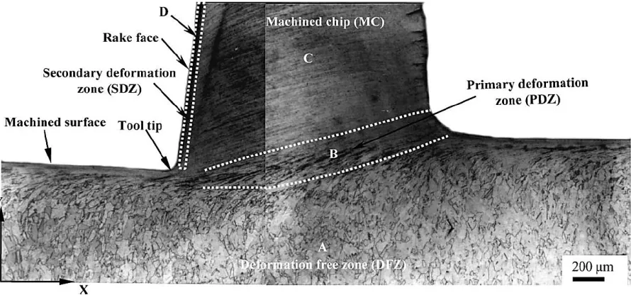
There are three regions of interest in a cutting process as shown in Figure 2.1 [10].
The plastic deformation characteristics of the material in the primary deformation zone,
friction-wear characteristics in the secondary deformation zone, and surface finish in the
tertiary deformation zone. Improvements in machining require combined knowledge of not
only physics, chemistry and material behaviour but also heat transfer, solid mechanics and
6
Figure 2.1: Deformation zones in a workpiece during orthogonal machining process [10]
2.1.1 Mechanisms and Mechanics of Metal Cutting
During machining, the plastic flow takes place in a localized region called shear plane
as shown in Figure 2.2 [10]. This shear plane is assumed to extend from the cutting tool
obliquely up to the uncut surface ahead of the tool. The sheared material begins to flow
along the cutting tool face in the form of small pieces called chips. The compressive force
applied to form the chip is called cutting force. When the chip flows over the tool, it wears
off the tool. Due to friction, frictional heat is produced. The heat generated raises the
temperature of the workpiece, cutting tool and the chip. The temperature rise in the cutting
tool tends to soften the material and causes loss of keenness in the cutting edge often
7
Figure 2.2: Mechanism of metal cutting in an orthogonal machining process showing a cutting tool with rake angle ‘α’ forming a chip with a shear angle ‘ø’ [10]
2.1.2 Types of Metal Cutting Process
Metal cutting processes are mainly classified into two types:
i. Orthogonal cutting process ii. Oblique cutting process
2.1.2.1 Orthogonal Cutting Process
Orthogonal cutting is a type of turning operation in which the cutting tool generates
a surface parallel to the original one [11]. In this process, the cutting tool is placed
perpendicular to the relative motion of the tool and work piece as shown in Figure 2.3 (a).
2.1.2.2 Oblique Cutting Process
In oblique cutting process, the cutting edge is inclined at an acute angle with the
8
Figure 2.3: Schematic of metal cutting showing (a) orthogonal cutting process where the cutting tool is perpendicular to the direction of machining, and (b) oblique cutting process where the
cutting tool is at an angle ‘𝜆’ to the direction of machining [11]
2.1.3 Chip Formation
The type of chip being formed during machining is influenced by a number of factors
such as mechanical properties of the workpiece material, tool signature and machining
parameters (cutting speed, feed rate, depth of cut, and cooling strategies).
The nature of the chip formed during a machining process is highly variable. Not all
metals and alloys withstand the high shear strain occurring in the region of the shear plane
without fracturing. The chips then become discontinuous and possess the advantage that
they are easily cleared from the cutting zone. However, most ductile materials do not
fracture at the shear plane which leads to the formation of continuous chips and causes
problems for the machinist.
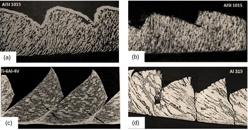
Chips can summarily be classified into two broad categories (Figure 2.4): Steady state
continuous chips and cyclic chips. Cyclic chips can in turn be classified into four different
types (Figure 2.5):
Wavy chips (Figure 2.5(a))
Segmental chips (Figure 2.5 (b))
9
Catastrophic shear chips or serrated chips (Figure 2.5 (c)) and
Discontinuous chips (Figure 2.5 (d))
Wavy chip formation is usually associated with cyclic variations in un-deformed chip
thickness, rake angle and clearance angle variation which mainly occurs due to chatter. The
limited rigidity and low damping ability of the cutting tools results in oscillation. Thus a
part of the machine tool system experiences resonance and consequently vibrates at large
amplitudes [12, 13].
Segmental chips are similar to continuous chips but with a periodic variation in chip
thickness. Such chips are formed due to the slow, forward movement of the plastic zone
that forms a ramp on the free surface of the chip. This is followed by a rapid return of the
plastic zone back towards the tool because of partial fracture, thus forming a step on the
chip segment. The instability in the primary shear zone is associated with negative
stress-strain material characteristics at large stress-strains. The instability in the secondary shear zone
arises from frictional relaxation oscillations leading to stick-slip friction on the tool. [12]
Catastrophic shear chips are usually observed in difficult-to-machine materials such
as Ti alloys. Depending on the thermal properties of the material, such chips are formed
even at very low cutting speeds. Two different theories concern the basic origin of this type
of chip formation. One theory describes the chip formation process on the basis of thermal
origin while the other is on the basis of periodic development of cracks in the original
surface of the work piece [14]. A detailed review of the two theories will be described in
10
Discontinuous chips are formed by upsetting the work material just ahead of the tool
tip and the failure mechanism is brittle in nature. During this process, strain concentrates
in a narrow band followed by crack formation ahead of the tool tip due to stress
concentration leading to rupture along the shear surface. [12, 15]
Figure 2.4: Two broad categories of chip segments formed during orthogonal machining of Ti 140A at different experimental conditions, namely, (a) continuous chips of Ti 140A formed at a
cutting speed of 30 m/min, feed rate of 0.13 mm/rev, (b) cyclic chips of Ti 140A formed at a cutting speed of 45 m/min and feed rate of 0.26 mm/rev [12]
Figure 2.5: Types of cyclic chip segments (a) wavy chips formed during machining AISI 1015 at a cutting speed of 30 m/min and feed rate of 0.13 mm/rev, (b) segmented chips formed during
machining of AISI 1015 at a cutting speed of 50 m/min and feed rate of 0.20 mm/rev, (c) catastrophic shear chips formed during machining of Ti-6Al-4V at a cutting speed of 5 m/s and feed rate of 0.12 mm/rev, (d) discontinuous chips formed during machining of 319Al at a cutting
speed of 35 m/min and feed rate 0.25 mm/rev [14, 15]
(a) (b)
(a) (b)
11
2.1.4 Forces and Stresses Generated during Orthogonal Cutting
During the machining process, force is applied to the tool to cut the materials and according to Merchant [16], in equilibrium conditions, the forces between the tool face and chip and between the work piece and the chip along the shear plane are equal. A force diagram is shown in Figure 2.6.
Figure 2.6: Merchant circle diagram showing the different forces generated during an orthogonal cutting process where 𝐹𝑐and FT or 𝐹𝑓are the cutting and feed forces, 𝐹𝑠 and 𝐹 are the
shear forces on the shear plane and rake face, 𝐹𝑁 and 𝑁 are the normal forces on the shear plane and rake face respectively, and 𝛼 are the shear and rake angles respectively, AC and A0 are the
cut and uncut chip thickness respectively. [16]
The relationship between various forces is as follows [16]:
𝐹𝑠 = 𝐹𝑐cos− 𝐹𝑓sin
𝐹𝑁 = 𝐹𝑐cos+ 𝐹𝑓sin
𝐹 = 𝐹𝑐sin 𝛼 + 𝐹𝑓cos 𝛼
𝑁 = 𝐹𝑐cos α − 𝐹𝑓sin α
(2.1)
(2.2)
(2.3)
12
where 𝐹𝑐 and 𝐹𝑓 are the cutting and feed forces, 𝐹𝑠 and 𝐹 are the shear forces on the shear
plane and rake face, 𝐹𝑁 and 𝑁 are the normal forces on the shear plane and rake face
respectively, and α are the shear and rake angles respectively.
2.1.5 Microstructural Deformation due to Orthogonal Cutting
Machining is a high-strain rate deformation process that generates large strains and
strain gradients in the work piece. Thus chip formation is accompanied by large plastic
flow at large strain rates [17]. A comprehensive microstructural analyses helps in
understanding the effect of machining on the work material and chip formation.
Quantification of different factors, such as chip thickness, shear angle also helps in
optimization of the machining process.
A cross-sectional optical micrograph showing the primary deformation zone in a
copper work piece that was subjected to orthogonal cutting is shown in Figure 2.7. Ramalingam and Black [17] used SEM and TEM to analyze the plastic deformation zone
at the root of the chip in steel. They concluded that a dynamic equilibrium exists between
strain hardening and recovery during the chip formation, and that plastic flow in machining
is a microscopically heterogeneous deformation process. Zhang and Alpas [19] observed
the deformed microstructure of aluminum alloy (6061 Al) and measured the shear angle
from the displacement of the extrusion lines, which act as inherent microstructural markers.
They also established a method to determine the plastic strain gradients in the material
ahead of the tool tip through the measured shear angle as shown in Figure 2.8 & Figure 2.9.
Ni et al. performed TEM investigations on copper [18] and aluminum [20] and observed
13
Figure 2.7: Cross sectional optical micrograph of Cu just ahead of the tool tip after orthogonal machining [18]
Figure 2.8: A computer generated image of the cross-section of the machined workpiece with the chip still attached. The image was obtained by determining the location of each point on the
14
Figure 2.9: Schematic diagram showing the measurement of shear angles ‘’ from the slopes of the deformation lines at an angle of ‘θ’ [19]
2.1.6 Estimation of Shear Angle
Zhang and Alpas [19] used the extrusion lines of 6061 Al as a marker and from the
change in orientation of these lines due to shearing, the shear angle was measured. A
computer generated, accurate representation of the flow lines they presented is shown in
Figure 2.9. The shear angle values were then computed from the slope of these lines (Figure
2.9) according to the following formula:
= tan−1(Δ𝑦
Δ𝑥)
Elmadagli and Alpas [21] used the same procedure to measure the angle in cases
involving orthogonally machined, commercially pure copper samples. However, instead of
flow lines, they used the deformed grains as the marker and found that the shear angle
varied from 9° to 21° from tool tip to chip root.
15 2.1.7 Estimation of Flow Stress
The microhardness of a material just ahead of the tool tip and below the machined
surface vary from one point to another. Tabor [22] related the amount of deformation with
the hardness, considering the fact that both these factors are related to elastic limit. The
criteria for plastic flow in a solid body subjected to principal stresses 𝜎1, 𝜎2, and 𝜎3 is given
by the von Mises relation [23]:
2𝜎02 = (𝜎1− 𝜎2)2+ (𝜎
2− 𝜎3)2+ (𝜎3− 𝜎1)2
where𝜎0 is the yield stress in uniaxial tension.
The meanpressure 𝜎𝑚 can be defined as follows:
𝜎𝑚 =
𝜎1+ 𝜎2+ 𝜎3 3
Based on assumptions made by Hill et al. [24], this equation can be solved. They
concluded that plastic yielding would occur when the mean pressure, 𝜎𝑚
𝜎𝑚 = 3𝜎0
The assumptions made by Hill et al. [24] are (i) The deformed area is not too large
compared with the size of the specimen, (ii) 𝜎𝑚 is independent of the applied load and size
of the indentation, (iii) Frictionless compression is performed.
Marsh [25] proposed that the Vickers hardness of a material could be related to the
corresponding flow stress,𝜎̅by the relation
𝜎̅ = 𝐻 3
(2.7)
(2.8)
16
This approximation is commonly used by researchers to predict the flow stress at different
positions on work material subjected to cutting operations [20, 21].
2.1.8 Estimation of Flow Strain
Equivalent plastic strain is a function of plastic deformation and is given by the
relation [23],
𝑑𝜀̅ =√2
3 [(𝑑𝜀1− 𝑑𝜀2)2+ (𝑑𝜀2− 𝑑𝜀3)2+ (𝑑𝜀3− 𝑑𝜀1)2]
1 2
where 𝜀1, 𝜀2, 𝜀3 are the three principal strains.
The above equation can further be reduced as follows:
𝜀̅ = [2
3(𝜀12+ 𝜀22+ 𝜀32)2]
1 2
For a material that has been subject to sliding, the equivalent strain generated in the
subsurface can be estimated by measuring the shear angle. The shear angle is measured
from subsurface microstructural features like flow lines or grain boundaries which bend in
the direction of sliding. The shear angle θ is equal to the angle between the tangent drawn
to the deformed marker at a point of interest and its original orientation at the point (before
deformation). The relation between equivalent plastic strain 𝜀 and shear angle θ is:
𝜀̅ =√3 3 tan 𝜃
Since the displacement of the feature, acting as a microstructural marker, is the result
of shear deformation parallel to the surface, any contribution of compression or rotation of
the features is ignored. This theory has been widely used for estimation of equivalent strain
in wear experiments [19, 26] and has been confirmed by Zaat et al [27]. This method is (2.10)
(2.11)
17
also useful for estimation of equivalent strain in other processes where substantial
deformation occurs.
2.2 Titanium Alloys – An Overview
Titanium is a chemical element with symbol Ti and atomic number 22. It is a lustrous
transition metal with a silver color, low density and high strength. It is highly resistant to
corrosion in sea water and chlorine environment. The element occurs within a number of
mineral deposits, principally rutile and ilmenite, which are widely distributed in the Earth's
crust and lithosphere, and it is found in almost all living things, rocks, water bodies, and
soils.
Titanium can be alloyed with iron, aluminum, vanadium, and molybdenum, among
other elements, to produce strong, lightweight alloys for aerospace (jet engines, missiles,
and spacecraft), military, industrial process (chemicals and petro-chemicals, desalination
plants, automotive, medical prostheses, orthopedic and dental implants, and other
applications.
2.2.1 Crystal Structure
Pure titanium exhibits an allotropic phase transformation at approximately 995 °C
(Figure 2.10 (a)), changing from a body-centered cubic crystal structure (β phase) at higher
temperatures to a hexagonal close-packed crystal structure (α phase) at lower temperatures.
The exact transformation temperature is strongly influenced by interstitial and
substitutional elements and therefore depends on the purity of the metal. The hexagonal
18
pure α titanium is 1.587, smaller than the ideal ratio of 1.633 for the hexagonal
close-packed crystal structure. The unit cell of the body centered cubic (bcc) β phase is illustrated
in Figure 2.10 indicating also one variant of the six most densely packed {110} lattice planes and the lattice parameter value of pure β titanium at 995 °C (a = 0.332 nm). The
close-packed directions are the four <111> directions.
Figure 2.10: (a) Phase diagram of Ti-6Al-4V showing the different types of titanium alloys based on the alloying composition, (b) Unit cell of hexagonal close packed structure and body centred
cubic structure of the α and β phase in a Ti-6Al-4V alloy [28]
(a)
(b)
19
2.3 Introduction to Ti-6Al-4V
Ti-6Al-4V or Ti64, is the most commonly used titanium alloy and is designated as a
Grade 5 alloy. It has a chemical composition of 6% aluminum, 4% vanadium, 0.25%
(maximum) iron, 0.2% (maximum) oxygen, and the remainder titanium [1]. It is stronger
than commercially pure titanium while having the same stiffness and thermal properties
(excluding thermal conductivity, which is about 60% lower in Grade 5 Ti than in CP Ti)
[28]. Among its many advantages, it is heat treatable and has an excellent combination of
strength, corrosion resistance and weldability.
This alpha-beta alloy is the workhorse alloy of the titanium industry. It is fully heat
treatable in section sizes up to 15mm and is used up to approximately 400°C (750°F). Since
it is the most commonly used alloy – over 70% of all alloy grades melted are a sub-grade
of Ti-6Al-4V, its uses span many aerospace airframe and engine component uses and also
major non-aerospace applications in the marine, offshore and power generation industries
in particular. Generally, Ti-6Al-4V is used in applications up to 400°C. It has a density
of roughly 4420 kg/m3, Young's modulus of 115 GPa, and tensile strength of 1000 MPa [28]. By comparison, annealed type 316 stainless steel has a density of 8000 kg/m3, modulus of 193 GPa, and tensile strength of only 570 MPa [28] and tempered 6061
aluminum alloy has 2700 kg/m3, 69 GPa, and 310 MPa, respectively.
2.3.1 Mechanical Properties of Ti-6Al-4V
Both the α and β phases deform [29, 30] in the Ti-6Al-4V alloy although the amount
of deformation is different for both the phases. The deformation of the phases in
6Al-4V alloy is dependent on the size of the grains. The deformation of fine grains in the
20
phase (Figure 2.11), which means the amount of deformation in the α and β phases are not
same. For the same alloy with a higher grain size, the system is a mixture of the iso-stress
and iso-strain types because both phases experience strain. Because of the larger size of the
β phase, a higher amount of stress is concentrated due to the larger slip distance that also
deforms the adjacent α grain [30].
Figure 2.11: TEM bright-field images of: (a) fine (3 μm); and (b) coarse (11 μm) grained Ti-6Al-4V deformed at 600°C with a strain rate of 10-3s-1 (ε=0.3) [30]
The mechanical characteristics found in Ti-6Al-4V are sensitive to processing
parameters such as strain rate and temperature. It is vital to understand their relationship to
study its deformation modes as well as to properly interpret the relationship between its
microstructure and processing variables along with its properties under different loading
conditions. The typical true stress-strain curves of Ti-6Al-4V alloys deformed at different
strain rates and temperatures are shown in Figure 2.12. It can be seen that true stress increases with true strain and reaches a maximum value before fracture. This depicts that
plastic deformation of Ti-6Al-4V alloy is greatly dependent on strain rate and temperature,
though the effect of the latter is more predominant [31]. The variation in yield strength and
21
increase in temperature. At higher temperatures (> 300 °C), the effect of thermal softening
resulted in decrease in strength of Ti-6Al-4V.
Figure 2.12: True stress-strain curves for Ti-6Al-4V at various temperatures and strain rates [31]
Figure 2.13: Variation of ultimate tensile strength and yield stress of Ti-6Al-4V with temperature [32, 33, 34]
Temperature (°C)
-200 -100 0 100 200 300 400 500
E
ngi
neer
ing
S
tres
s
(M
P
a)
200 400 600 800 1000 1200 1400 1600 1800 2000
Ultimate Tensile Strength
22
Figure 2.14 shows the effect of temperature on strain rate sensitivity. Strain rate sensitivity (𝑚) is calculated using the following equation for constant temperature and
strain [23]:
𝑚 = (𝜕 ln 𝜎 𝜕 ln 𝜀̇) 𝜀, 𝑇
where 𝑚 is the strain rate sensitivity, 𝜎 is the flow stress, 𝜀 ̇is the strain rate, 𝜀 is the strain and 𝑇 is the temperature.
For all four strain rate conditions, the sensitivity increases. Figure 2.12 and Figure 2.14
show that when the strain rate is higher, the strain hardening decreases at a critical
temperature. However, in cases with low temperatures, the effect of strain rate is not as
significant. The sensitivity increases at a very high rate when the temperature is sufficiently
high (e.g. above 500°C) when deforming at a constant strain rate.
Figure 2.14: Variations of strain rate sensitivity as a function of temperature for deformation at a true strain of 0.05 under different strain rate ranges [31]
23
The hardness of the annealed Ti-6Al-4V alloy increases from 33.5 HRC at room
temperature to about 42 HRC at low temperatures, as shown in Figure 2.15 [35]. Titanium
alloys experience an increase in strength at low temperatures [36]. Compared to α- Ti,
Ti-6Al-4V shows a sharp rise in flow stress below room temperature. At around 0 K, the flow
stress of Ti-6Al-4V is 1600MPa, whereas for α-Ti, it is around 750MPa [36]. In the
low-strain-rate deformation process, the flow stress of Ti-6Al-4V reaches a plateau at around
600K, and there is a well-defined discontinuity at temperatures between 400K and 800K.
Within this temperature range, the flow stresses of α- Ti and Ti-6Al-4V are very close. This
feature is not found in the high-strain-rate deformation process. Above this temperature
range, strain hardening decreases drastically due to the dynamic recovery that results in a
decrease in flow stress [36]. These characteristics are shown in Figure 2.16
.
24
Figure 2.16: Temperature dependence of yield stress of Ti-6Al-4V at low and high strain rates compared to α-Ti [36]
2.4 Machining of Ti-6Al-4V
Titanium alloys are known as difficult-to-machine materials. There are a myriad of
problems in machining titanium which depend on the type of alloy being machined. Based
on the available literature, some basic challenges include variation of chip thickness, high
thermal stress, high pressure loads, springback, and residual stress.
To address these problems, latest techniques such as application of high pressure
coolant, cryogenic cooling, tap testing, thermally enhanced machining, hybrid machining,
and use of high conductive cutting tool and tool holder have also been discussed and
correlated.
Machinability is judged in terms of four different criteria: (i) chip formation, (ii)
25
product [7]. Research in this field started in the early 1950s and has continued in order to
optimize the machining operations.
2.4.1 Machinability of Ti-6Al-4V
Properties such as high strength-to-weight ratio, strength at high temperature,
ductility and fracture resistance make Ti-6Al-4V a suitable option for various industrial
applications, although these properties make it difficult to machine. Many researchers have
noted different problems that arise during Ti-6Al-4V machining and their relation to
material properties. [1 – 8]
1. Generation of high localized cutting zone temperatures at the tool-workpiece
interface during machining of Ti-6Al-4V. Machining operation accumulates high
amount of deformation within the material, and a large portion of this deformation
converts into heat. The heat becomes localized which causes high temperature
generation within a narrow zone leading to further deformation occurring in that
particular region. This localization (or heterogeneous deformation) results in cyclic
chip formation as discussed in Section 2.1.3. [1 – 5]
2. Formation of cyclic chip segments as mentioned above causes oscillations in cutting
and thrust components of forces that eventually result in chatter. [6]
3. Approximately 80% of the generated heat is conducted into the tool during
machining Ti-6Al-4V (due to low thermal conductivity), whereas in cases using
steel, the absorbed heat is approximately 50%. This high amount of heat, along with
the oscillation produced during machining titanium alloys, is thought to be the reason
26
4. Chips come into contact with the tool as they form and slide on the rake face of the tool during machining. When two different materials slide against each other, a solid
solution may form. Wear on the dissolving material occurs from solution wear,
diffusion wear or delamination wear. All these wear processes are related to the
chemical stability of the materials [8]. Titanium alloys show high chemical reactivity
with tool materials such as uncoated carbide and poly-crystalline diamond tools.
In summary, material properties are the primary reasons for difficulties in machining
titanium alloys. Thus studying the characteristics of the chips is necessary to solve or
minimize problems since they help to understand the material behaviour. This study would
be useful in overcoming the problems in machining Ti alloys.
2.5 Chip Formation Mechanisms
The Ti-6Al-4V alloy produces serrated chips not only under conventional,
high-speed machining but also at low cutting high-speeds [36]. Two mechanisms for serrated chip
formation were proposed initially by researchers. These were the adiabatic shear
mechanism and periodic crack development mechanism. However, the research work
conducted later tends to support the adiabatic shear mechanism.
2.5.1 Adiabatic Shear Mechanism
Metallic materials strain harden when plastically deformed. Further deformation
requires the application of extra amounts of stress. Due to heat entrapment in titanium
alloys, two opposing effects, strain hardening and thermal softening, occur simultaneously
![Figure 2.10: (a) Phase diagram of Ti-6Al-4V showing the different types of titanium alloys based on the alloying composition, (b) Unit cell of hexagonal close packed structure and body centred cubic structure of the α and β phase in a Ti-6Al-4V alloy [28]](https://thumb-us.123doks.com/thumbv2/123dok_us/1386018.1171289/39.612.180.478.209.657/different-titanium-alloying-composition-hexagonal-structure-centred-structure.webp)
![Figure 2.13: Variation of ultimate tensile strength and yield stress of Ti-6Al-4V with temperature [32, 33, 34]](https://thumb-us.123doks.com/thumbv2/123dok_us/1386018.1171289/42.612.210.442.134.345/figure-variation-ultimate-tensile-strength-yield-stress-temperature.webp)
![Figure 2.14: Variations of strain rate sensitivity as a function of temperature for deformation at a true strain of 0.05 under different strain rate ranges [31]](https://thumb-us.123doks.com/thumbv2/123dok_us/1386018.1171289/43.612.198.451.411.642/figure-variations-strain-sensitivity-function-temperature-deformation-different.webp)
![Figure 2.15: Variation of hardness of Ti-6Al-4V with temperature measured on a Rockwell C-scale [35]](https://thumb-us.123doks.com/thumbv2/123dok_us/1386018.1171289/44.612.171.487.392.629/figure-variation-hardness-ti-temperature-measured-rockwell-scale.webp)
![Figure 2.19: Measured and predicted cutting tool temperatures under different machining environments [54]](https://thumb-us.123doks.com/thumbv2/123dok_us/1386018.1171289/56.612.165.492.71.322/figure-measured-predicted-cutting-temperatures-different-machining-environments.webp)
![Figure 2.20: Comparison of (a) flank wear, (b) cutting zone temperature under wet and cryogenic machining of Ti-6Al-4V with increasing cutting velocity [61]](https://thumb-us.123doks.com/thumbv2/123dok_us/1386018.1171289/58.612.163.486.186.628/figure-comparison-temperature-cryogenic-machining-increasing-cutting-velocity.webp)
![Figure 2.21: (a, b) Average wear of the primary flank during dry cutting and using cryogenic coolant, (c, d) Average wear of the nose during dry cutting and using cryogenic coolant [62]](https://thumb-us.123doks.com/thumbv2/123dok_us/1386018.1171289/60.612.178.473.75.488/figure-average-cutting-cryogenic-coolant-average-cryogenic-coolant.webp)
![Figure 2.22: Variation of (a) surface roughness, and (b) dimensional accuracy with machining time under different cutting environments [52]](https://thumb-us.123doks.com/thumbv2/123dok_us/1386018.1171289/62.612.170.479.72.298/figure-variation-roughness-dimensional-accuracy-machining-different-environments.webp)