CAN Protocol Implementation for Industrial Process
and Tracking System
Prashant. I#1 and Mr. Shrikanth Rao S K #2
#1 M.Tech student Dept. of Electronics and Communication Engineering, VCET Puttur D.K, Karnataka, India 574203 #2 Assistant Professor Dept. of Electronics and Communication Engineering, VCET Puttur D.K, Karnataka, India 574203 ______________________________________________________________________________________________________
Abstract - To implementation of industrial parameter control through CAN protocol by using ARM processor. CAN is a multi-master broadcast serial bus standard for connecting electronic control units (ECUs).Each node is able to send and receive messages, but not simultaneously, a message (consisting primarily of an ID usually chosen to identify the message-type/sender and up to eight message bytes) is transmitted serially onto the bus, signal pattern codes the message (in NRZ) and is detected by all nodes. The devices that are connected by a CAN network are typically electronic control units, A CAN Message never achieves these gadgets specifically, however rather a host processor and a CAN controller are needed between these devices and the bus. Bit rates up to 1Mbit/s are conceivable at system lengths underneath 40 m. Decreasing the bit rate allows longer network distances (125kbit/s at 500 m). The programming language used for developing the software to the ARM processor is Embedded/Assembly. The KEIL cross compiler is utilized to alter, aggregate and investigate this system. Small scale Flash software engineer is utilized for smoldering the created code on Kiel into the ARM processor Chip. Tracking system implemented on sensor data by using the GSM.
Key words - CAN bus, ARM Processor, Complier, Sensors, GSM Module
________________________________________________________________________________________________________
I. INTRODUCTION
Controller–area network (CAN or CAN bus)is a vehicle bus standard designed to allow controllers and gadgets to speak with one another inside of a vehicle without a host PC.CAN is a message based convention, designed for various applications like automotive applications , modern robotization and medicinal gear . The configuration of a framework demonstrates the operation of a few subsystems copying car and mechanical applications over the CAN transport. The introduction into the vehicle design has allowed an almost symbiotic relationship between the driver and vehicle by providing a sophisticated & intelligent driver-vehicle interface through an intelligent information network. This paper talks about the development of such a control framework for the vehicle which is known as the advanced driving conduct, which consists of a joint mechanism between the driver and vehicle for perception, decision making and control. In mid 80s, German BOSCH organization imagined the CAN BUS which is a serial data communication.CAN provides a mechanism which can be used in the hardware and the software using which different electronic modules can communicate with each other using a common cable. Communication speed is up to 1MBPS. CAN is an International Standardization Organization (ISO) defined serial communications bus originally developed for the automotive industry to replace the complex wiring harness with a two-wire bus. The CAN communication protocol is a carrier sense, multiple-access protocol having collision detection and arbitration on message priority (CSMA/CD+AMP). CSMA (Carrier sense multiple access) means that each node on a bus must wait for a prescribed period of inactivity before attempting to send a message. CD+AMP mean that collisions are resolved through a bit-wise arbitration, based on a pre-programmed priority of each message in the identifier field of a message. CAN transmission medium is designed by: High-level transmission line CANH; and Low-level transmission line CANL.
Figure1. CAN topology
II. Controller Area Network (CAN)
commercial ventures including building mechanization, therapeutic, and assembling. The CAN communications protocol, ISO-11898: 2003 explains how information is passed between devices on a network.
CAN protocol data Frame
Figure 2. CAN data frame
A CAN network can be configured to work with two different message (or "frame") formats: the standard or base frame format (or CAN 2.0 A), and the extended frame format (or CAN 2.0 B). The only difference between the two formats is that the "CAN base frame" supports a length of 11 bits for the identifier, and the "CAN extended frame" supports a length of 29 bits for the identifier, made up of the 11-bit identifier ("base identifier") and an 18-bit extension("identifier growth"). The refinement between CAN base edge plan and CAN expanded casing configuration is made by utilizing the IDE bit, which is transmitted as predominant in the event of a 11-bit outline, and transmitted as passive if there should be an occurrence of a 29-bit outline. CAN controllers that support extended frame format messages are also able to send and receive messages in CAN base frame format. All frames begin with a start-of-frame (SOF) bit that denotes the start of the frame transmission.
CAN have four types frame:
Data frame: a frame containing hub information for transmission. Remote frame: a asking for the transmission of a particular identifier. Error frame: a frame transmitted by any hub distinguishing a lapse.
Overload frame: a frame to infuse a deferral in the middle of information and/or remote edge.
III. MODEL TO IMPLEMENT CAN WITH ARM PROCESSOR
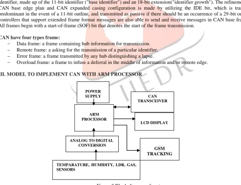
Figure 3.Block diagram of system
Figure 3.Shows the block diagram of CAN control system. The different nodes are ECUs, which are connected to each other utilizing CAN transport. The gadgets that are associated by a CAN arrange are typically actuators, sensors, and other control devices. These devices associated by implication to the bus, through a host processor and a CAN controller. In proposed CAN bus prototype for automation, LPC2129 ARM7 TDMI-S processor is used as host processor. MCP2551 is Stand-Alone CAN Controller with SPI Interface. MCP2551 is utilized as CAN transceiver. LPC2129 ARM processor is having inbuilt CAN
ARM PROCESSOR
CAN TRANSCEIVER
ANALOG TO DIGITAL CONVERSION
LCD DISPLAY
GSM TRACKING POWER
SUPPLY
controller utilised for designing monitor node. This framework comprises of CAN driver IC MCP2551, temperature sensor, light, fuel, smoke, Gas Sensor, GSM Modem, Matrix Keyboard and the LCD display (16x4) interfaced with the microcontroller. In CAN transceiver and CAN controller, it comprises of one expert hub and slave hubs.ARM as the master controller (Engine Control Module) which controls the status with various sensors. Two ARM ICs are used as slave nodes to receive the inputs of status. The correspondence between these sensors is finished by utilizing CAN controller. Slave controller gets the signals from pressure, temperature, humidity, fuel level, and IR obstacles and GSM send to ace controller with high velocity rate. Master controls the status and sends the feedback to operator panel by providing advanced data's through LCD show and alerts. Here Operator interface is advanced sort. By this administrator can undoubtedly see the signals and ready to control and sends the signal to GSM. GSM will send the message to the mobile for tracking sensor data.
IV. HARDWARE DESIGN ARM Architecture
The ARM is a general purpose ARM is a broadly useful 32-bit chip, which offers elite and low power utilization. The ARM architecture is based on Reduced Instruction Set Computer (RISC) principles. The LPC2119/LPC2129 is based on a 16/32 bit ARM7 CPU with ongoing imitating and implanted follow support, together with 128/256 kilobytes (kB) of embedded high speed bash memory. A 128-bit wide memory interface and extraordinary quickening agent building design empower 32-bit code execution at greatest clock rate. It contains a 16/32-bit ARM7 microcontroller in a tiny LQFP64 package. With their compact 64 pin bundle, low power utilization, different 32-bit clocks,4-channel 10-bit ADC, 2 advanced CAN channels, PWM channels, Real Time Clock and Watchdog and 46 GPIO lines with up to 9 external interrupt pins these controllers are especially suitable for car and modern control applications and additionally medicinal frameworks and deficiency tolerant support buses. It does not contain MMU (memory management unit). But because of its low price, reliability and other factors, it is broadly utilized as a part of different mechanical controllers.
MCP2551:The MCP2551 is a fault-tolerant, high-speed CAN device that serves as the interface between the physical bus and a CAN protocol controller. It will operate at speeds of up to 1 Mb/s.
Figure 4.MCP2551 pin diagram
Table 1.MCP2551 pin diagram description
Pin no Pin name Function
1 TXD Transmit data input
2 VSS Ground
3 VDD Supply voltage
4 RXD Receive data output
5 Rs Reference output voltage
6 CANH CAN low level output voltage I/O 7 CANL CAN high level output voltage I/O
8 VREF Slop control -input
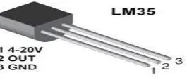
Temperature Sensor LM 35
The LM35 is temperature sensor with a precision integrated-circuit, and its yield voltage is directly relative to the temperature in Celsius the temperature of any machine to which it is associated or the temperature of nature around it is identified with these sensors. Temperature sensor is a simple sensor which gives the yield into type of simple analog signal. This analog signal is fed to ADC which will convert this signal into digital form. After converting into digital form, the digital temperature signal is processed with the help of microcontroller as per the application requirement. The output voltage changes linearly at a rate of 10mV per degree Celsius (Centigrade).
Gas Sensor MQ6:
MQ6 is a profoundly touchy gas sensor to petroleum based gasses. MQ6 gas sensor is a 6 pin device which requires 5 volt DC maximum and is derived from a zener based power supply. It consists of a warming component inside the sensor, that becomes hot at 5 volt and remains stand by. In the atmosphere when the gas molecules detected by the sensor are between 100 ppm to 1000 ppm, , its output turns high and triggers the transistor to activate the buzzer.
MQ6 Gas sensor
Light Sensor LDR: A LDR is a segment that has a (variable) resistance that progression with the light power which falls upon it
and permits them to be utilized as a part of light detecting circuits. A light ward resistor chips away at the rule of photograph
conductivity, which is an (hence resistivity) reduces when light is absorbed by that material.
Light Dependent Resistor LDR
Sound sensor: Sound Detector is the electrets mouthpiece container – without it, couldn't change over acoustic vitality into electrical vitality. These cases have a few idiosyncrasies that have to see with a specific end goal to apply them effective.
Sound sensor
Buzzer:
Buzzers are used in a system as an indicator or to grab the attention as an emergency situation. Buzzer act as a panic horn which indicates the need of instant attention as the condition goes haywire.
Liquid Crystal Display:
LCD is used in a project to visualize the output of the application. We have used 16x4 LCD which indicates 16 columns and 4 rows. So, we can write 16 characters in each line.
The Global System for Mobile Communication
GSM is a computerized portable telephony framework. We can send short text messages to the required authorities as per the application, with the help of GSM module interfaced. The GSM module can send the data out by SMS (Short Message Service) message, including ongoing position of system. GSM uses a variation of (TDMA) time division multiple access furthermore, is the most broadly utilized of the three advanced remote telephony advancements (TDMA, GSM, and CDMA).
GSM MODEM
IV SOFTWARE DESIGN:
Keil u Vision 4.0 for programming purpose, Keil IDE, Proteus for software simulation, Flash magic for downloading programmer in the chip
V.METHODOLOGY
In this project master-slave concept has implemented. One master will control two slaves. The communication between theses using CAN protocol. The CAN is a serial communication bus which will reduce wiring. The controller used for all ARM-7 micro controllers LPC 2129. The special feature of this IC is that it has two advanced CAN channels in built for serial communication. The CAN controller used is MCP 2551 which will help to transfer data serially from one port to another.CANH and CANL are the two lines for transfer of information. Different sensors are interfaced to the two slaves. An LCD and a matrix keypad is interfaced to the master. All the data from sensors will be displayed on the LCD.LM35 will sense the surrounding temperature and it will be converted into digital form through analog to digital convertor, and the temperature will be displayed on the LCD. As the temperature increases, voltage will increase and ADC count increases. LDR is used for detection of light in the car. As the intensity of light decreases, the voltage decreases, and ADC count will increase. And the digital value will be displayed on the LCD. For detection of gas in the system, a metallic strip is used. Initially it is at logic 0. When gas is detected, the strip gets short and the buzzer is activated. GSM are also interfaced which will track the sensor data.
VI. RESULT AND DISCUSSION
Project has successfully tested and implemented of CAN protocol for different sensors, also information of sensor is converted digital form through analog to digital convertor.LCD displays the converted digital values of all sensors.
Figure 5 Shows working of other sensors that is, temperature, light, gas and fire sensors.
Figure 5 sensors connection part Figure 6 shows the master board connecting all sensors to it.
Figure 6 shows the master board
Figure 7 shows the slave working model with LCD, all data display on shown in LCD. Figure 8 shows the before transmission of all sensors data LCD, light, fuel, switched off
Figure 8 shows the before transmission of all sensors data LCD
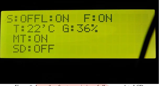
Figure 9 shows the transmitted data on LCD here light ,fire is ON AND GAS Sensor and metal is detected.
Figure 9 shows the after transmission of all sensors data LCD
V. CONCLUSION
This paper represents successfully implemented of the project that shows communication between different electronic control units within a system using a CAN protocol.CAN protocol mainly used in controlling application purpose without wired limited distance up to 40 meter. Main features of this project are to implement CAN protocol for different sensors or ECUs in system, controlling along with tracking the sensor data by using a GSM.
VI. ACKNOWLEDGEMENT
I am thankful to, Dr. Lingangowda Kulkarni principal of Vivekanada College Engineering and Technology, Dr.Shivprakash Koliwad project co-ordinate, ShrikrishnaShastri assistance professor, HOD and my assistant professors of ECE Dept. of Vivekanada College Engineering and Technology, Puttur D.K. for providing the necessary facilities and guidance for executing the model and the preparation of the paper
VII. REFERENCE
[1] D.V.S.Reddy1, Alia Sultana2, K.Madhavi Latha3 and M.Haritha4 “CAN protocol implementation for industrial process” International Journal of Applied Engineering and Technology ISSN: 2277-212X (Online) An Online International Journal Available at http://www.cibtech.org/jet.htm 2012 Vol. 2 (1) January-March, pp1-5/Reddy et al.
[2] Vemula Pallavi, N. Raju “CAN protocol implementation for industrial process” International Journal of Computer Science and Mobile Computing Vol.2 Issue. 11, November- 2013, pg. 106-112.
[3] Mr.Abhijit K Chougule, Prof. R.J. Vaidya “Milk Dairy Automation Using CAN Protocol: A Paradigm for Industry Automation” Volume 3, Issue 9, September 2013 ISSN: 2277 128X International Journal of Advanced Research in Computer Science and Software Engineering Research Paper.
[4] CH.Mounika, K.S.Roy, Mahaboob Ali “Motor Speed Control Based On Temperature Using Can Protocol” International Journal of Engineering Trends and Technology (IJETT) - Volume4Issue4- April 2013
[5] R. Manoj Prasanth, S.Raja, L.Saranya “Vehicle Control Using CAN Protocol For Implementing the Intelligent Braking System (IBS)” International Journal of Advanced Research in Electrical, Electronics and Instrumentation Engineering (An ISO 3297: 2007 Certified Organization) Vol. 3, Issue 3, March 2014
[6] Mani kanth alapati, dr .N.S.Murthi sarma, V.Anuragh, CH.V.S.Subrahmanyam “Design & Implementation of Automotive Intelligent Node CAN bus in Hybrid Electric Vehicles using ARM7” International Journal of Advanced Research in Electronics and Communication Engineering (IJARECE) Volume 1, Issue 5, November 2012
[7] A.K.Ray and Mazidi (2000). The 8051Micro controllers and embedded systems.