Vol. 3, Issue 4, April 2015
Copyright to IJIRCCE 10.15680/ijircce.2015.0304177 3835
A Modified Design of FFT Architecture for
Wi-Max OFDM Standards to Support both
Variable Length and Multi-streaming
M.Manobala
1, N.Manikanda Deverajan
2, Dr.A.Nagappan
3,Dr.D.Vinod Kumar
4M.E (VLSI), VMKV Engineering College, Salem, Tamilnadu, India1
Associate Professor, Dept. of ECE, VMKV Engineering College, Salem, Tamilnadu, India2
Principal, VMKV Engineering College, Salem, Tamilnadu, India3
Associate Professor, Dept. of ECE, VMKV Engineering College, Salem, Tamilnadu, India4
ABSTRACT: The FFT architecture was reconfigurable for supporting both variable length and multistreaming. They are able to process architecture in 1 stream of 2048-pt FFT or two streams of 1024-pt FFT or 4 stream of 512-pt FFT. The architecture having SDF pipelined stages and in each stage radix-2 butterfly is calculate. The sampling frequency is changed in depend upon the FFT length. The word length and buffer length in each stage is calculate by FFT length. Power consumption was decreases by use of latch gating. Experimental result show that the design increase the throughput expected by the Wi-Max standard. The architecture used fewer amounts of the total available FPGA resources and clock frequency of the system was 13.67 MHz achieved.
KEYWORDS: MIMO-Multiple Input Multiple Outputs, DFT- Discrete Fourier Transform, FPGA- Field Programmable.
I.INTRODUCTION
In Recent days Wireless Systems are developed to increase the transmission rate of the system. Wi-Max is the Wireless Standard that combines MIMO and OFDM systems. This Wi-Max achieves higher data transmission because of the combination of MIMO and OFDM.MIMO used multiple spatial streams to increase performance. FFT is the signal processing algorithm. In order of transmission of multiple spatial streams FFT requires multiple data streams. But to handle multiple data streams FFT need multiple processor. In usage of multiple processors made more hardware resources and increase the power consumption and also Wi-Max wireless standard transmits data in different defined channel bandwidths (5 MHz, 10 MHz, 20 MHz) this needs variable FFT length (i.e.) scaling the FFT to defined channel bandwidth to maintain a constant carrier spacing.
In order to fulfil the above requirements of the standard a reconfigurable architecture that can support both variable length and multistreaming simultaneously that requires a research on pipelined FFT architecture [1]-[10]. Hence this paper proposed a reconfigurable FFT architecture that can support Variable Length and Multi streaming simultaneously A Variable length for system that can process of 512,1024,2048,4096 points presented in [3]. For WLAN standards a 64 points proposed in [5].
It consists of modified SDF, radix-2 FFT Architecture. A dynamic voltage and frequency is proposed in [6]. The clock gating is used to clock the modules only when they are needs which reduce power consumption [9]. For Multistream processing this co-efficient storage is organized in order to reduce the no of memory access.
II. PROPOSED ARCHITECTURE
Vol. 3, Issue 4, April 2015
Copyright to IJIRCCE 10.15680/ijircce.2015.0304177 3836
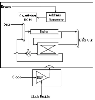
Fig 1: Proposed Architecture of FFT
DIT is the algorithm used in FFT. The DIT algorithm has the property that they have S stages of the algorithm. Hence the calculated FFT was said to be N=2^s points [13]. This DIT algorithm is used because that the initial stages of the pipelined architecture is shared between schemes with different FFT length and multiple streams. The input streams interleaving and sampling frequency of the system was changed .
III HARDWARE IMPLEMENTATION
Single stage of the proposed pipeline architecture was shown in the figure 2. Each pipelined stage consists of a radix-2 butterfly element, a complex multiplier, complex co-efficient memory and data management units. This result in a total of eleven butterfly elements and ten complex multipliers for the entire design. Additionally, the design consists of a centralised control unit to synchronize the data flow.
Fig 2: A modified SDF stage of the proposed architecture
The butterfly unit consists of the complex adder and the complex subtractor. Complex is the combination of real and imaginary parts. The butterfly unit produce the sum and imaginary parts.
Vol. 3, Issue 4, April 2015
Copyright to IJIRCCE 10.15680/ijircce.2015.0304177 3837
Stage Bufferlength
Stage 1 1024
Stage 2 512
Stage 3 256
Stage 4 128
Stage 5 64
Stage 6 32
Stage 7 16
Stage 8 8
Stage 9 4
Stage 10 2
Stage 11 1
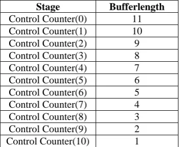
Table 1: Buffer length for the pipelined stages
The table 1 displays the buffer length for various stages of the proposed architecture. The depth of the buffer can be varied to store a minimum of one word to 1024 words. The input data is written to the first register and shifted to the consecutive registers. ROM is used as the co-efficient memory which is single port memory and clock enable. The size of the ROM in each stage was calculated as 2^(s-1) where s is the stage number. Two ROMs are used in this architecture to store real and imaginary parts separately. On positive clock edge ROM outputs are in words but it was not registered. Twiddle factor is to be stored was generated in Matlab function. The word length and the twiddle factor length were same. Up-counter is used to address the ROM. The output width depends on the stages where it is used. The output was reset when the counter reaches its maximum value
Centralised control unit is used to control the counter and it s used to synchronize and control the data flow path. The control unit consists of eleven bit up counter. When the input arrives counter is enabling, when its maximum value (i.e.) 11 was reached its get reset to its initial value. In each stage switches the input every n/2^s clock cycles by multiplexer, Hence in each stage each bit of counter output can be directly connect to the selected pin of multiplexer. The control unit also provides the clock gating condition power down the stages. The length of the FFT and the no of streams desired the counters of the control unit. The control signal associates with output switching multiplexer were shown in table 2.
Stage Bufferlength
Control Counter(0) 11
Control Counter(1) 10
Control Counter(2) 9
Control Counter(3) 8
Control Counter(4) 7
Control Counter(5) 6
Control Counter(6) 5
Control Counter(7) 4
Control Counter(8) 3
Control Counter(9) 2
Control Counter(10) 1
Table 2: Control signals associated with output switching multiplexer
IV VARIABLE LENGTH AND MULTI STREAMING
Vol. 3, Issue 4, April 2015
Copyright to IJIRCCE 10.15680/ijircce.2015.0304177 3838 corresponding FFT output samples. X [n] 8 represents the two streams of 8-pt input data sequence. X[k] 8 is the FFT output of the output of the two streams. To compute 16-pt, the complete signal flow graph is used by joining stage-4 with stage-3.
In the case of two 8-pt FFTs, the inputs indexed as 0,1,2,3,4,5,6,7 are the data samples of the first 8-pt FFT stream and the inputs indexed as 0’,1’,2’,3’,4’,5’,6’,7’ are the data samples of the second stream [14-15]. The input streams are interleaved and given as input to the system. In the signal flow graph, the solid lines indicate the data flow of the first stream of FFT and the dotted lines indicate the dataflow of second 8-pt FFT. As three stages are required to calculate 8-pt FFT, the output X[k] 8 is taken from the third stage. The outputs are also interleaved. It can be observed from the flow graph that twiddle factors are the same in a stage irrespective of the FFT length or the number of streams.
Fig 3: Variable length DIT FFT signal flow graph.
V.AREA AND PERFORMANCE RESULT
To analyze the dynamic performance of the FFT architecture implemented, the VHDL implementation of the FFT architecture was synthesised using Xilinx integrated simulation environment tool. Spartan 3E FPGA was the target device. Spartan 3E (XC3S100E) and package is TQ144 is used for the requirement of the cost sensitive application. The architecture was synthesised with the following specification and settlings in the tool.
The FPGA clock is 20 MHz
The input output word length of the samples is 16.
The Synthesis tool can be optimizing the architecture either for speed or area to minimize hardware resources.
Vol. 3, Issue 4, April 2015
Copyright to IJIRCCE 10.15680/ijircce.2015.0304177 3839 Hardware
Resources
Utilized Resources Available Resources Utilization (%)
Number of Slices
461 960 48
Number of Slice Flip
348 1920 18
Number of 4 input LUIs
865 1920 45
Number of IOs
34 108 31
Number of IOBs
34 108 31
Number of GCLKs
1 108 4
Table 3: FPGA device utilization
VI RESULT POWER CONSUMPTION
Power estimation of a circuit is an important aspect of a system design. The power consumed by the circuit largely affects the dynamic performance of the circuit. Total power consumed by a design implemented in the FPGA is the sum of the two power quantities namely static power and dynamic power. The transistor leakage current of the device results in static power consumption, where as dynamic power of a circuit is associated with the design activity, switching input/output nodes and the clock frequencies associated with the FPGA. Dynamic power of a circuit is calculated using the below equation
Dynamic power = 0.5fclkCLV 2dd
The result of the timing analysis using time analyzer in the Xilinx ISE Tool was given below
Maximum Frequency:600.00 MHz.
Clock period :16.667 ns.
Total number of path /Destination ports: 4327193/358.
Delay :16.667 ns (level of logic:17).
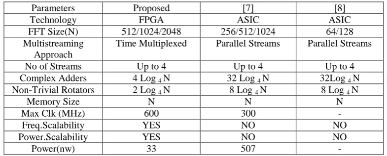
VII COMPARISON OF VARIABLE LENGTH AND THE MULTISTREAMING
Parameters Proposed [7] [8]
Technology FPGA ASIC ASIC
FFT Size(N) 512/1024/2048 256/512/1024 64/128
Multistreaming Approach
Time Multiplexed Parallel Streams Parallel Streams
No of Streams Up to 4 Up to 4 Up to 4
Complex Adders 4 Log 4 N 32 Log 4 N 32Log 4 N
Non-Trivial Rotators 2 Log 4 N 8 Log 4 N 8 Log 4 N
Memory Size N N N
Max Clk (MHz) 600 300 -
Freq.Scalability YES NO NO
Power.Scalability YES NO NO
Vol. 3, Issue 4, April 2015
Copyright to IJIRCCE 10.15680/ijircce.2015.0304177 3840
VIII CONCLUSION AND FUTURE WORK
A reconfigurable FFT architecture to cover all the cases of Wi-Max wireless OFDM standard was proposed, designed and verified in this thesis work. The FFT requirements were tabulated after a brief study of the OFDM wireless standards. The FFT architecture was designed based on the Wi-Max FFT requirements table. Decimation-in-Time FFT algorithm was used. The architecture was designed with eleven modified Single Delay Feedback stages. Each stage calculates aradix-2 FFT. The FFT architecture is reconfigurable for variable length and multiple streams. The architecture processes a single stream of 2048-pt FFT, up to two streams of 1024-pt FFT or up to four streams of 512-pt FFT. The architecture processes continuous streams of data. The architecture is power efficient. Clock gating technique was used to reduce power consumption. Clock gating was used to power down individual modules (butterflies and complex multipliers) or a complete stage, when not in use. As far as it is known, the architecture proposed in this thesis work is the first architecture to cover all the cases of the Wi-Max wireless standard.
REFERENCES
[1] M. Garrido, J. Grajal, M. S´anchez, and O. Gustafson, “Pipelined radix-2k feed forward FFT architectures,” IEEE Trans. VLSI Syst., vol. 21,no. 1,
pp. 23–32, Jan. 2013.
[2] S. He and M. Torkelson, “Design and implementation of a 1024-point pipeline FFT processor,” May 1998, pp. 131–134.
[3] Y. O. Park and J.-W. Park, “Design of FFT processor for ieee802.16m MIMO-OFDM systems,” in Int. Conf. Information Comm. Tech.
Convergence, Nov. 2010, pp. 191–194.
[4] M. Garrido, K. K. Parhi, and J. Grajal, “A pipelined FFT architecture for real-valued signals,” IEEE Trans. Circuits Syst. I, vol. 56, no. 12, pp.
2634–2643, Dec. 2009.
[5] H.-L. Lin, H. Lin, R. Chang, S.-W. Chen, C.-Y. Liao, and C.-H. Wu,“A high-speed highly pipelined 2N-point FFT architecture for a dual OFDM
processor,” in Int. Conf. Mixed Design Integrated Circuits Syst., Jun. 2006, pp. 627–631.
[6] Y. Chen, Y.-W. Lin, Y.-C. Tsao and C.-Y. Lee, “A 2.4-Gsample/s DVFS FFT processor for MIMO OFDM communication systems,” IEEE
J.Solid-State Circuits, vol. 43, no. 5, pp. 1260–1273, May 2008.
[7] S.-N. Tang, C.-H. Liao and T.-Y. Chang, “An area- and energy-efficient multimode FFT processor for WPAN/WLAN/WMAN systems,” IEEEJ.
Solid-State Circuits, vol. 47, no. 6, pp. 1419–1435, Jun. 2012.
[8] S. Li, H. Xu, W. Fan, Y. Chen, and X. Zeng, “A 128/256-point pipeline FFT/IFFT processor for MIMO OFDM system IEEE 802.16e,” Jun.2010, pp. 1488–1491.
[9] T. Ahmed, M. Garrido, and O. Gustafson, “A 512-point 8-parallel pipelined feed forward FFT for WPAN,” Nov. 2011, pp. 981–984.
[10] T. Lenart and V. Owall, “Architectures for dynamic data scaling in 2/4/8k pipeline FFT cores,” IEEE Trans. VLSI Syst., vol. 14, no. 11, pp.
1286–1290, Nov. 2006.
[11] A. V. Oppenheim and R. W. Schafer, Discrete-Time Signal Processing. Prentice-Hall, 1989.
[12] M. Garrido, O. Gustafson, and J. Grajal, “Accurate rotations based on coefficient scaling,” IEEE Trans. Circuits Syst. II, vol. 58, no. 10, pp.662–
666, Oct. 2011.
[13] A. Wenzler and E. Luder, “New structures for complex multipliers and their noise analysis,” vol. 2, Apr. 1995, pp. 1432–1435.
[14] G.Ramachandran, T Muthumanickam, B.SuganyaAbiramavalli, T.Sheela,,Arunkumar Madhuvappan,L.Vasanth” Study and implementation of Green Power in Campus Environment” International Journal of Electronics and communication Engineering & Technology, ISSN:0976-6472, Pages . 325-331 Vol:3,Issue:1,– June2012
[15] V. Prasanth, C. Arunkumar Madhuvappan, Dr. T. Muthumanickam, T. Sheela, “GPS Based Advanced Railway Level Crossing Management System Using FPGA” International Journal of Innovative Research in Computer and Communication Engineering Vol. 3, Issue 4, April 2015 pp 3172-3176 ISSN(Online): 2320-9801
[16]G.Ramachandran, .T.Sheela, G.SureshKumar, T.Muthumanickam .S.Kannan, S..Vaishnudevi, “Application of Robot” SSRG International Journal of Electronics and Communication Engineering (SSRG-IJECE) ISSN: 2348 – 8549 – volume1, issue8 pages: Oct 2014
[17] G.Ramachandran, T.Muthumanickam, T.Sheela , R.Thirunavukkarasu” Simulation Transfer of Files from PC To PC Using LAN Trainer Kit” International journal of trend in research and developments. ISSN 2394-9333 Page 1-6 Volume-2 Issue-2 Apr 2015
[18] M. Garrido, J. Grajal, and O. Gustafson, “’Optimum circuits for bit reversal’,” IEEE Trans. Circuits Syst. II, vol. 58, no. 10, pp. 657–661,Oct.
2011.
[19] M. Garrido, “Efficient hardware architectures for the computation of the FFT and other related signal processing algorithms in real time,” Ph.D. dissertation, Universidad Polit´ecnica de Madrid, 2009.