ABSTRACT
MATTSON, MICHAEL GLENN. Multi-objective Optimization of Semi-active Vehicle Suspension Control. (Under the direction of Gregory D. Buckner).
Multi-objective Optimization of Semi-active Vehicle Suspension Control
by
Michael Glenn Mattson
A thesis submitted to the Graduate Faculty of North Carolina State University
in partial fulfillment of the requirements for the degree of
Master of Science
Mechanical Engineering
Raleigh, North Carolina 2010
APPROVED BY:
_______________________________ ______________________________
Dr. Gregory Buckner Dr. Lawrence Silverberg
Committee Chair
BIOGRAPHY
ACKNOWLEDGMENTS
I would like to thank all of those who patiently supported me through this long journey. John Crews was a truly invaluable facilitator and research partner. Dr. Greg Buckner displayed great patience and advice throughout a difficult road to completion. Lord Corporation has been so good to me, especially Doug Ivers, who has always been a great sounding board and interested advisor.
Countless family and friends have been so very artful in the way they have asked “How’s that thesis coming along?” seven hundred twenty-three times along the way, that it barely felt like I was taking long at all.
The boys at AWANA and all the kids at Saturday club have done more than they know in providing a perfect diversion on a weekly basis.
I have been truly blessed with wonderful parents and siblings without whom I would not be where I am.
TABLE OF CONTENTS
LIST OF TABLES ... v
LIST OF FIGURES ... vi
1.Introduction ... 1
2.Vehicle Model ... 3
Magnetorheological Dampers ... 5
Vehicle and Terrain Parameters ... 7
3.Multi-Objective Genetic Algorithms ... 8
Objective Functions ... 11
Absorbed Power ... 11
Mean Dissipated Power ... 11
MOGA Parameters ... 12
Population Initialization ... 14
Skyhook Control ... 15
Feedback Linearization ... 16
Sliding Mode Control ... 16
Optimal Control ... 18
4.Results ... 20
Multi-objective Performance Frontiers ... 20
MOGA Results ... 24
5.Discussion ... 30
6.Conclusion ... 32
LIST OF TABLES
LIST OF FIGURES
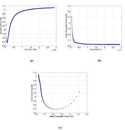
Figure 1. Quarter Car Model ...4 Figure 2. Control bounds for semi-active dampers ...5 Figure 3. Genetic Algorithm structure ...10 Figure 4. Effects of skyhook parameter csky on objective functions: absorbed power (a);
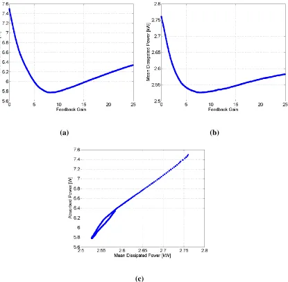
mean dissipated power (b); performance frontier (c) ...21 Figure 5. Effects of FLC gain on objective functions: absorbed power (a);
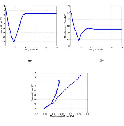
mean dissipated power (b); performance frontier (c) ...22 Figure 6. Effects of SMC switching gain on objective functions: absorbed power (a);
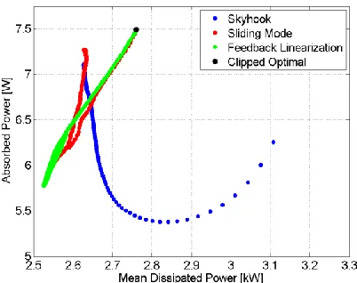
mean dissipated power (b); performance frontier (c) ...23 Figure 7. Performance frontiers for control algorithms ...24 Figure 8. MOGA Results: Pareto frontier with extreme controllers noted (a);
population number vs. generation (b); best absorbed power vs. generation (c); evolution of the Pareto frontier (d) ...25 Figure 9. Simulation results for controllers identified in Figure 8:
control input for controller 1 (a); and controller 2 (b);
vehicle displacement for controller 1 (c); and controller 2 (d); vehicle acceleration for controller 1 (e); and controller 2 (f);
comparison in the temperature rise from ambient (g) ...27 Figure 10. Comparison between Pareto frontier and performance frontiers for other control
1.
Introduction
The design of control algorithms for semi-active vehicle suspensions has been an active research field for over forty years [1, 2]. Semi-active actuators, such as magnetorheological (MR) fluid dampers, offer many of the benefits of their fully active counterparts with less cost and complexity [3, 4]. While active vehicle suspensions remain confined to research labs, MR fluid dampers are now commercially available in automobiles from GM, Audi, and Holden and are being incorporated into heavier offroad vehicles.
Numerous control algorithms have been developed for semi-active suspensions [1, 3-12]. To date, the most prevalent algorithm is “skyhook control”, wherein the controller seeks to emulate a damper connected between the vehicle body (sprung mass) and an inertial reference. In other words, the controller attempts to minimize absolute velocity of the sprung mass. Additional methods for semi-active control include a “relative control” algorithm with simplified measurement requirements but similar reductions in sprung mass acceleration [5], a modified skyhook control using sprung mass jerk rather than velocity, and “limited relative displacement control” employing high damping control ratios at large relative suspension deflections [6]. Another approach targets optimal ride for a specific point in the vehicle, not necessarily the center of gravity [7].
the difficulties of constrained optimal control [9]. In deriving the “clipped optimal” control input, the damper force is assumed to be linear and unbounded. The actual input is then constrained to the passivity limits of semi-active control. The “clipped optimal” controller has been shown to be nearly optimal.
To date, the performance of new semi-active controllers is often measured against other control schemes (including optimal) [7], passive systems [13], or fully active implementations [5]. The primary focus of these comparisons has often been on ride quality, i.e. minimizing sprung mass acceleration, while other performance metrics (such as “wheel hop” or handling [14]) have been considered only infrequently. However, as semi-active dampers move from theory and experimental prototyping into the production realm, new challenges and considerations arise. In particular, heavier vehicle applications require that dampers be equipped for large energy dissipation or risk elevated temperatures. Elevated temperatures can be detrimental to the fluid, seals, and other components of a damper. Therefore, it is beneficial to evaluate new control algorithms based on multiple performance objectives including damper temperature rise. Recently, several control schemes for providing temperature relief through control decisions have been considered, but these only provided small improvements and inconsistent results [15].
schemes. In addition, such a tool could provide a robust justification for selecting a specific real-time control strategy.
A multi-objective genetic algorithm (MOGA) is demonstrated in this thesis to establish the limits of performance in terms of both ride quality and damper thermal response. Multi-objective optimization can lead to a frontier of optimal solutions, known as the Pareto frontier [16], and genetic algorithms (GAs) are ideally suited to creating the Pareto frontier due to their inherent ability to consider multiple solutions simultaneously. While the multi-objective problem can be formulated as an optimal control problem involving the two performance criteria, this requires arbitrary weighting parameters, is impossible to solve analytically, and is often difficult to solve numerically. By utilizing a MOGA to create this frontier of solutions, control designers can assess and compare the performance benefits of various control algorithms and weigh developmental effort against expected performance increase. However, the outcome of this effort does not provide a novel method for controlling the vehicle in real-time because the control scheme is developed with full knowledge of course terrain and independent of decision making schemes.
2.
Vehicle Model
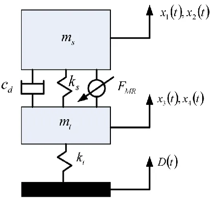
A two degree-of-freedom quarter car model is used to simulate the vertical dynamics of a high-mobility heavy off-road vehicle, Figure 1. The model consists of a tire (unsprung) mass
t
mass by a suspension system with stiffness ks and nominal passive damping cd. FMR is the control force produced by the MR damper.
Figure 1. Quarter Car Model
The dynamics of the quarter car are governed by equations (1)-(4).
1 2
x t x t (1)
2 3 1 4 2
1
s d MR
s
x t k x t x t c x t x t F t
m
(2)
3 4
x t x t (3)
4 3 3 1 4 2
1
t s d MR
t
x t k D t x t k x t x t c x t x t F t
m
(4)
1
Magnetorheological Dampers
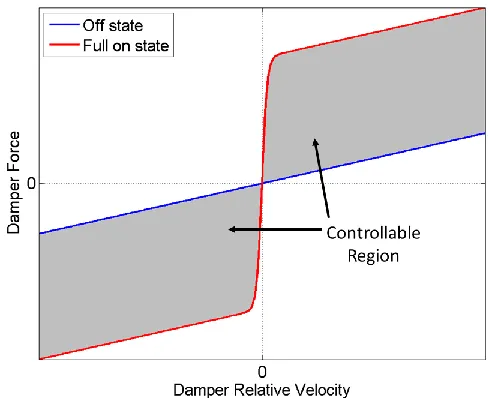
Viscous dampers generate speed-dependent force as the working fluid interacts with internal orifices or valves. Controlled dampers modulate these forces by mechanically modifying the valve area or by modifying the fluid’s viscosity as it passes through the valve. Magnetorheological (MR) fluid dampers accomplish the latter by manipulating the voltage applied to an electromagnetic coil in proximity to the valve. An MR damper’s lower (off state) force bound is fixed by the non-magnetized fluid viscosity and the valve area. Its upper (on state) force bound is determined by the fluid’s iron content, current limits, magnetic flux saturation, and other hardware constraints. Generally, a MR damper’s on state and off state produce a controllable force range similar to that shown in Figure 2.
Various methods exist for modeling the damping characteristics of MR fluid actuators [17, 18]. Many control algorithms assume a bilinear control input [10]; however a hyperbolic tangent relationship between the force and relative velocity more accurately models the damping characteristics, implemented as
maxtanh
4
2
MR
F t u t F x t x t , (5)
where u t
is the normalized control input (constrained to 0u t
1). Fmax is the maximum achievable damping force and is a scalar that ensures 90% of the maximum achievable force is reached at a damper velocity of 1.5 /
.Equations (1) - (4) neglect certain nonlinearities (suspension bump-stops, tire lift-off, Coulomb friction, etc.) that could be important. Instead, these equations focus on one critical nonlinearity, the damping relationship of Figure 2, to demonstrate the design of preliminary control algorithms for GA initialization. However, additional nonlinearities could readily be incorporated if desired.
The damper’s thermal response is characterized using the first order lumped capacitance model
5 5
1
therm
x t h x t j t
m
, (6)
The instantaneous dissipated power j t
is calculated according to
4
2
d
4
2
MR
j t x t x t c x t x t F . (7)
Vehicle and Terrain Parameters
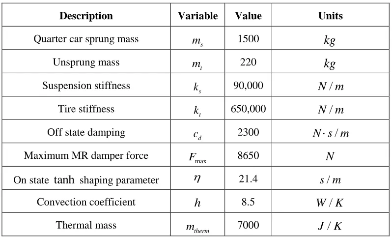
The vehicle parameters listed in Table 1 are representative of heavy off-road vehicles in production today. These vehicle parameters, coupled with the offroad terrain data and speed (25km hr/ ) used in simulations, represent a significant challenge for semi-active vehicle suspensions due to the extreme mechanical and thermal loads exerted on the damper.
Table 1. System parameters
Description Variable Value Units
Quarter car sprung mass ms 1500 kg
Unsprung mass mt 220 kg
Suspension stiffness ks 90,000 N m/
Tire stiffness kt 650,000 N m/
Off state damping cd 2300 N s m /
Maximum MR damper force Fmax 8650 N
On state tanh shaping parameter 21.4 s m/
Convection coefficient h 8.5 W K/
The offroad terrain used for vehicle simulations is a 6.35cm (2.5inch) RMS pseudo-random course profile developed by Lord Corporation at their vehicle test facility in Moncure, North Carolina. The course features a series of crests of varying heights spaced in a pseudo-random manner.
3.
Multi-Objective Genetic Algorithms
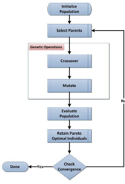
Genetic algorithms are heuristically developed optimization methods based on principles of natural selection. GAs seek to minimize (or maximize) one or more objective functions using computational techniques motivated by biological reproduction. These algorithms mimic natural selection by creating populations of “individuals” (in this case semi-active vehicle suspension control inputs), selecting “parents” to create “children”, and the “fittest” individuals survive (are preserved for use in the next generation). The fitness of an individual is measured using one or more objective functions.
problems [23]. In [23], the authors found that GAs were better suited to solving discrete time optimal control problems than other popular optimization methods.
Figure 3. Genetic Algorithm structure
can only be achieved by increases in others), then a Pareto frontier of solutions exist [16]. Both optimization problems can contain equality and inequality constraints on the design variables.
Objective Functions
The two objective functions used in this research, absorbed power and mean dissipated power, reflect ride quality and thermal performance, respectively. Ride quality considers the comfort of the passengers in the vehicle and is important for safety and fatigue mitigation. Thermal performance, or the effect of damper control on temperature rise, is important for minimizing component wear and extending seal durability.
Absorbed Power
Absorbed power is a widely accepted measure of ride quality [25,26]. The vertical component of absorbed power F1 is given by
2 1
1
N i i i
F C A
, (8)where Ai is the RMS acceleration within the ith spectral frequency band. The constants Ci
are functions of frequency and are available in [25].
Mean Dissipated Power
4 2
4
2
max
4
2
0 2 tanh f t d f
x t x t c x t x t u t F x t x t dt
F
t
. (9)Dampers are designed to convert mechanical power into heat; this obviously leads to elevated temperatures in the damping hardware. Mean dissipated power is an effective measure of thermal performance because the average mechanical dissipated power is directly proportional to the temperature rise.
Of added interest, it is noted that two papers also link the amount of energy dissipated in the suspension to the forward power draw on the vehicle in off-road applications [27, 28]. While this aspect is not considered here, minimizing mean dissipated power may offer simultaneous benefits to hardware temperature and forward power requirements.
MOGA Parameters
The design variables for this multi-objective optimization problem are the discrete control inputs u i
, where i is the sample number 0 i 46, 000. The discretization time interval is T0.001sec (hence each simulation duration is 46.0 seconds). Note that each control input is subject to the constraints of magnetorheological dampers in (5): 0u i
1. The state equations (1) - (4) and (6) are integrated using a 4th-order Runge-Kutta algorithm in order to evaluate the objective functions (8) and (9) for each individual in the population.Real value encoding is used for the control inputs
0,1 kwhere k
u i is the control input at time t iT and generation k.
One advantage of GAs is their ability to find optimal solutions via random initialization. However, random initialization incurs the cost of slower convergence times. By relying on well-established control techniques to create the initial population, computational requirements can be greatly decreased. For the application presented here, the population is initialized with 1000 individuals created using a number of well known control strategies (described in Population Initialization, below).
After selecting the parents, crossover and mutation operations are performed. Arithmetic crossover is performed on 90% of the selected parents, whereby two children are created from the weighted sum of two parents,
1 1
k k k
j n m
k k k
l n m
C rP r P
C r P rP
, (11)
where k j
C is the th
j child in generation k, Pnk is the nth parent in generation k, and
r
is a random scalar value 0 r 1. Children of the remaining 10% of selected parents are exact copies of the parents.Crossover is performed until the population number is doubled. Then each individual has a 5% probability of undergoing mutation. If an individual is selected for mutation, each control input in the string has a 5% chance of being randomly replaced. Finally, only the Pareto optimal individuals survive to the next generation. For the termination criterion, a generation limit is used, and the resultant population is evaluated to determine convergence.
Population Initialization
85% of the initial MOGA population is created from popular and well-documented semi-active control algorithms (presented in greater detail below): skyhook control (40%), feedback linearization (40%), and sliding mode control (5%). By utilizing these well-known control algorithms, convergence of the MOGA to the Pareto frontier is facilitated. The remaining 15% of the population is initialized with constant control input (5%), sinusoidal control input (5%), and random control inputs (5%). For the constant control input, 0
j
for all i, where
r
is a random scalar 0 r 1. For the sinusoidal control input,
0
0.5 0.5sin j
u i r i h , where
r
is again a random scalar. For the random control input
0
j
u i r i , where a new random value r i
is generated for each control input in the string.Each of the control algorithms are developed in the continuous time domain assuming full state measurement. While estimation of states is an important consideration in the design and implementation of real controllers, the purpose of this study is to provide a theoretical upper limit on controller performance. Furthermore, the MOGA adapts the control inputs without regard of the states or even a specific feedback form.
Skyhook Control
Skyhook control is one of the most popular semi-active control algorithms [4, 6]; it has been shown to provide an excellent combination of performance and ease of implementation for vibration absorption in vehicles and structures [4]. Skyhook control is motivated by placing a theoretical damper between the sprung mass (the vehicle body) and an inertial vertical reference. Skyhook control is defined by
2
4 2
max
max 0.0, min 1.0,sgn c x tsky
u t x t x t
F
, (12)
Feedback Linearization
Feedback linearization is an intuitive and effective control algorithm that attempts to cancel dynamic nonlinearities and impose desired closed loop linear dynamics [29]. The algorithm works well when the system dynamics are well known (minimal modeling uncertainty) and can be represented in companion form. However, in practice, un-modeled dynamics and uncertainty can greatly limit the effectiveness of this approach.
For the quarter car model, it can be shown that using the control input
3 1 4 2 2
maxtanh 4 2
s d s
k x t x t c x t x t m x t
u t
F x t x t
, (13)
reduces the sprung mass acceleration (2) to
2 2
x t x t , (14)
where represents a desired linear feedback gain. However, this gain may not be achievable in practice, as the control input is limited to 0u t
1.Sliding Mode Control
SMC guarantees that a specified “sliding surface”, or manifold, is reached in finite time and that the system stays on that surface for all time [30]. For the quarter car model, the sliding surface is specified to be the sprung mass velocity
2
s t x t . (15)
A candidate Lyapunov function is
21 2
V s t . (16)
To ensure robust stability, the time derivative of this Lyapunov function given in (17) needs to be negative definite (V 0). The time derivative of (16) is
3 1 4 2
max 4 2
1
tanh
s d
s
V s t k x t x t c x t x t
m
u t F x t x t
. (17)
If the control input u t
is chosen to be
3 1 4 2
max 4 2
sgn tanh
s d s
k x t x t c x t x t m s t
u t
F x t x t
, (18)
(17) simplifies to
sgn
V s t s t s t s t , (19)
of this gain has a large impact on system performance, it is considered a tunable parameter for the initial MOGA population.
Optimal Control
Optimal control synthesis for semi-active suspensions is complicated due to the two point boundary value problem (involving the state and costate equations) and the required use of Pontryagin’s Minimum Principle. These difficulties can be overcome using an approach known as “clipped optimal” control [9]. In “clipped optimal” control, the control inputs are developed using optimal control theory [33] without regard to the constraints of the semi-active systems (0u t
1). When implemented, the control input is saturated or “clipped” based on these constraints. Since the goal of the study is to create the multi-objective Pareto frontier, a simplified optimal controller is developed similar to the one in [9]. The genetic algorithm is expected to provide any additional optimization that was lost in using this suboptimal controller in place of solving the full nonlinear optimal control problem.In order to simplify the analytical result, a linear control law is assumed as
maxtanh
4
2
v t u t F x t x t . (20)
2 2
1 2 2
0
f
t
J
x t j t dt , (21)where 1 and 2 are scalars that weight the acceleration x t2
and power j t
, (7), respectively. The solution of (21) requires formulating the Hamiltonian,i i
H L f , (22)
where fi refers to state equations given in (1) - (4) and (6) , and the Lagrangian is
2 2
1 2x t 2j t
L . (23)
In order to determine the optimal control v t*
, a boundary value problem involving the state and co-state equations has to be solved. A number of techniques exist, including discretization, pseudo-spectral methods, and shooting. However, since the main goal of this thesis is developing the Pareto frontier, which MOGAs are better suited for, only the case of minimizing acceleration squared is presented (1 1 and 2 0). It can be shown that this case essentially simplifies to full state feedback linearization with the optimal control input
*
3 1 4 2
s d
v t k x t x t c x t x t . (24)
4.
Results
The results presented here first detail the initial population performance with respect to the objective functions (8) and (9). It is important to understand how the controller gains affect performance in order to seed the initial MOGA population. The results of the MOGA are presented next. Controllers providing the lowest absorbed power are then compared to those providing the lowest mean dissipated power.
Multi-objective Performance Frontiers
Three of the control algorithms presented (skyhook, feedback linearization and sliding mode) have tunable parameters (controller gains) that significantly affect the system responses, while the “clipped optimal” controller has a unique solution. The tunable parameters for each controller include csky for the skyhook algorithm (12), the switching gain
for the SMC (18) and the closed loop feedback gain
for the feedback linearization controller (13).
(a) (b)
(c)
The effects of the feedback linearization controller’s (FLC) feedback gain on these objective functions are presented in Figure 5. In contrast to the skyhook controller, the performance frontier of the feedback linearization controller, Figure 5(c), shows that a single optimal value of exists.
(a) (b)
(c)
The effects of the SMC’s switching gain
on these objective functions are presented in Figure 6. The performance frontier for the SMC, Figure 6(c), is similar to the FLC; a single value of
is optimal.(a) (b)
A comparison of all three performance frontiers is presented in Figure 7. Objective function values for the “clipped optimal” controller are also indicated in this figure. As shown in the figure, the skyhook controller produces the lowest absorbed power, and the FLC produces the lowest mean dissipated power.
Figure 7. Performance frontiers for control algorithms
MOGA Results
Figure 8(d). However, the “best” absorbed power is improved and the MOGA finds better combinations of both objective functions.
(a) (b)
(c) (d)
Figure 9. Simulation results for controllers identified in Figure 8: control input for controller 1 (a); and controller 2 (b); vehicle displacement for controller 1 (c); and controller 2 (d);
(a) (b)
(e) (f)
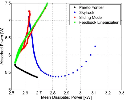
A comparison between the Pareto frontier generated by the MOGA and the performance frontiers of the other controllers used in the initial population is shown in Figure 10. As shown in the figure, it is possible to achieve performance between those that are more optimal in mean dissipated power, such as feedback linearization, and those that are more optimal in absorbed power, such as skyhook.
Figure 10. Comparison between Pareto frontier and performance frontiers for other control algorithms
5.
Discussion
vehicle parameters used in the simulation. These results indicate that it may be possible to switch from a skyhook algorithm to a feedback linearization or SMC as the damper temperature exceeds a specified threshold.
The Pareto frontier shows improvement over all points in the initial population. The MOGA is unable to find a control input that achieves a lower mean dissipated power than the best feedback linearization controller. It is worth noting that similar results were observed in a prior study [15]. The controller associated with this point is essentially bang-bang control, as seen in Figure 9(b).
All objective improvements are within 10% of the best initial designs for the various solutions. As expected, the well researched topic of vehicle control has resulted in algorithms that are difficult to improve. This means that a well tuned skyhook algorithm might expect a 10% lower steady state temperature rise on this terrain through control changes. Similarly, a feedback linearization algorithm might expect approximately 7% improvement in ride with some further considerations of the algorithm.
The MOGA provides a frontier of possible solution points, but does not determine any single design that is optimal out of that group. Decisions concerning how to weigh the balance between these objectives and others that are not considered remain.
6.
Conclusion
A method has been demonstrated for obtaining the optimal control signal for a semi-active vehicle suspension using a multi-objective genetic algorithm. The results of this method provide valuable insights concerning the absolute performance of any given control scheme. Therefore, a designer is no longer relegated to comparing new controllers to other controllers, active systems, or passive options. Furthermore, there comes a point where more tuning of a controller provides better results, but with diminishing returns on the effort involved in exploring the tuning space. The MOGA method provides some idea of what improvement there is left to explore and whether future efforts will produce significant results.
Unfortunately, the MOGA does not provide a real-time solution for implementing control decisions to move toward optimal. The MOGA’s value is evaluating a controller’s merits apart from the typical comparisons and revealing the remaining optimality space. Future work will concentrate on finding real-time controllers that are able to operate along the Pareto frontier.
REFERENCES
1. D. Karnopp, M. J. Crosby, and R. A. Harwood. “Vibration control using semi-active force generators.” ASME Journal of Engineering for Industry. 96(2): pp 619-626, 1974. 2. R. S. Sharp and D. A. Crolla. “Road Vehicle Suspension System Design - a Review.”
Vehicle System Dynamics. 16(3): pp 167-192, 1987
3. N. A. Jalil. “Comparative Study and Analysis of Semi-active Vibration-Control Systems.” Journal of Vibration and Acoustics. vol. 124, pp 593-605, 2002.
4. D. Margolis. “Semi-active Heave and Pitch Control for Ground Vehicles”. Vehicle System Dynamics. 11: pp 31-42, 1982.
5. M. R. Jolly and L. R. Miller. “The Control of Semi-active Dampers Using Relative Feedback Signals”. SAE Technical Paper 892483, 1989.
6. Y. Shen, M.F. Golnaraghi, and G.R. Heppler, “Semi-active Vibration Control Schemes for Suspension Systems Using Magnetorheological Dampers.” Journal of Vibration and Control. 12(3), 2006.
7. C. Grenger, “Active and Semi-active Suspension Control for Specific Point Isolation of Vehicles.” M.S. Thesis, University of California, Davis, California, 2009.
8. K. Yi and B. A. Song, “A New Adaptive Sky-hook Control of Vehicle Semi-active Suspensions.” Proceedings of the Institution of Mechanical Engineers. 213: pp 293-303, 1999.
9. T.J. Gordon, “Non-linear Optimal Control of a Semi-active Vehicle Suspension System.”
Chaos, Solitons & Fractals. 5(9): pp 1602-1617, 1995.
10.D. Hrovat, D. Margolis, and M. Hubbard. “An Approach Toward the Optimal Semi-active Suspension.” Journal of Dynamic Systems. 110: pp 288-296, 1998.
11.H. E. Tseng, and K. Hedrick. “Semi-active Control Laws – Optimal and Suboptimal.”
Vehicle System Dynamics. 23(1): pp 545-569, 1994.
12.L. Jansen and S. Dyke. “Semi-active Control Strategies for MR Dampers: a Comparative Study.” Journal of Engineering Mechanics. 126(88): pp 795-803, 2000.
13.G. Verros, S. Natsiavas, and C. Papadimitriou. “Design Optimization of Quarter-car Models with Passive and Semi-active Suspensions under Random Road Excitation.”
14.J. Lu and M. DePoyster. “Multiobjective Optimal Suspension Control to Achieve Integrated Ride and Handling Performance.” IEEE Transactions on Control Systems Technology. 10 (6), November 2002.
15.G. Bohan. “Control Algorithms to Reduce Dissipated Power and Temperature in Magnetorheological Fluid Dampers.” M. S. Thesis, University of California, Davis, California 2009.
16.K. Deb. “Multi-objective Genetic Algorithms: Problem Difficulties and Construction of Test Problems.” Evolutionary Computation. 7(3): pp 205-230, 1999.
17.B. F. Spencer, S. J. Dyke, M.K. Sain, and J.D. Carlson. “Phenomenological Model for a Magnetorheological Damper.” Journal of Engineering Mechanics. 123(3): pp 230-238, 1997.
18.İ. Şahin, T. Engin, and Ş. Çeşmeci. “Comparison of Some Existing Parametric Models for Magnetorheological Fluid Dampers.” Smart Materials and Structures. 19, 2010. 19.M. Srinivas and L. Patnaik. “Genetic Algorithms: a Survey.” IEEE Computer. 27(6): pp
17-26, 1994.
20.S. Rajeev and C.S. Krishnamoorthy. “Genetic-algorithms-based Methodologies for Design Optimization of Trusses.” Journal of Structural Engineering. 123(3): pp 350-358, 1997.
21.A. E. Baumal, J. J. McPhee, and P.H. Calamai. “Application of Genetic Algorithms to the Design Optimization of an Active Vehicle Suspension System.” Computational Methods Applied in Mechanical Engineering. 163: pp 87-94, 1998.
22.R. Dimeo and K. Lee. “Boiler-turbine Control System Design Using a Genetic Algorithm.” IEEE Transactions on Energy Conversion. 10(4): pp 752-759, 1995.
23.Z. Michalewicz, C. Janiko, and J. Krawczjk. “A Modified Genetic Algorithm for Optimal Control Problems.” Computers and Mathematics with Applications. 23(2): pp 83-94, 1992.
24.C. M. Fonseca and P.J. Fleming. “Genetic algorithms for multiobjective optimization: Formulation, discussion, and generalization.” Proceedings from the Fifth International Conference on Genetic Algorithms. S. Forest, San Mateo, CA. pp 416-423, 1993.
27.D. Karnopp. “Power Requirements for Traversing Uneven Roadways.” Vehicle System Dynamics. 7(3): pp 135-152, 1978.
28.D. A. Crolla and A. M. A. Abouel Nour. “Power Losses in Active and Passive Suspensions of Off-road Vehicles.” Journal of Terramechanics. 29(1): pp 83-93, 1992. 29.J.J. Slotine and W. Li. Applied Nonlinear Control. Prentice Hall, NJ, 1991.
30.H. Khalil. Nonlinear Systems. Prentice Hall, NJ, 2002.
31.C. Kim and P. Ro. “A sliding mode controller for vehicle active suspension systems with non-linearities.” Proceedings of the Institution of Mechanical Engineers. 212: pp 79-92, 1998.
32.M. Yokoyama, J.K. Hedrick, and S. Toyama. “A model following sliding mode controller for semi-active suspension systems with MR dampers.” Proceedings of the American Control Conference. pp 2652-2657, 2001.