MODELLING OF AIRCRAFT CESSNA 210 FOR
IMPACT ANALYSIS ON NUCLEAR BUILDING
Alexander Siefert1, Fritz-Otto Henkel2, and Eyad Aldoghaim3
1
Manager High Speed Dynamics, Wölfel Beratende Ingenieure, Germany
2
Senior Manager, Wölfel Beratende Ingenieure, Germany
3Project Engineer, Wölfel Beratende Ingenieure, Germany
ABSTRACT
Nowadays the impact of aircrafts on buildings of nuclear power plants is carried out via the integral simulation approach. Thereby the impact of passenger aircrafts and military jets on the reactor building is in the focus as a failure could lead to dramatic consequences for the operation model of the power plant.
In this article an impact loading of a smaller aircraft of type Cessna 210 will be presented for a crash on typical concrete structures. Therefore a finite element model of this aircraft for the FE-solver ABAQUS is generated and validated via existing data (France, 1988). Then this model is applied for a crash analysis in combination with FE-models of concrete walls. The structures represented general designs of typical civil engineering structures. The thickness of the investigated setups varies between 40, 60 and 80 cm with bending reinforcement at the front and the back side. The material properties of steel and concrete represent general setups.
The crash scenario, i.e. the impact velocity, is defined based on the impulse of a published load-time-curve (Ft-curve). For the walls with a thickness of 40 and 60 cm damage is observed at the impact area. The damage occurs due to shear failure but finally no perforation of the aircraft is observed. For the impact of the wall with 80 cm almost no damage can be observed. Nevertheless it must be mentioned that the investigated walls and their boundary conditions represent only a general setup not taking into account material properties and percentage of reinforcement of specific structures.
INTRODUCTION
In principle, impact is an interaction phenomenon between the projectile, as e.g. missile or aircraft, and the civil engineering structure. A separate investigation of the load-time-function and its application on the structure is in general possible. Compared to the real crash this represents somehow a simplification as the direct interaction is not considered. Further only a straight impact can be investigated neglecting effects due to the flight approach direction and the outer surface of the building.
The work presented here is a numerical crash simulation of the aircraft type Cessna 210 on typical setups of outer concrete walls for buildings in the nuclear sector. The simulation uses the integral approach, i.e. the aircraft, the structure and their interaction are considered in one model. The numerical model was generated with the pre-processor HyperMesh (2013) and the analysis was carried out using ABAQUS (2013) with an explicit solver scheme.
AIRCRAFT FINITE ELEMENT MODEL
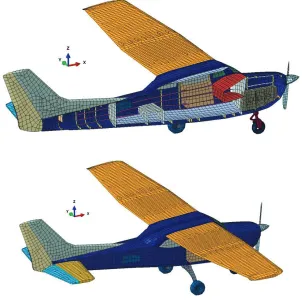
The geometric information for the setup of the finite-element model for the Cessna 210 is taken from published CAD data and is checked via information of this airplane and the manufacturer. The modelling consists mainly of shell and beam elements. Further discrete masses are used for representing the fuel and the payload. In figure 1 the model is show for an isometric view and a cross section of the symmetric plane.
Figure 1. FE-model of Cessna 210: Cross section and isometric view.
In the model setup the following main features influencing the impact load are considered:
• Fuselage including ribs and stringers
• Wings including stringers and ribs
• Horizontal and vertical tail
• Fuel distributed over wings
• Payload distributed over fuselage
The general properties of Cessna 210 can be summarized as follows:
• Ordinary Take-off weight (MTOW) 1.4 t
• Length 8.60 m
• Width 11.20 m
• High 2.90 m
MATERIAL MODELS
Steel and aluminium alloys are the mainly materials are used within the model. With respect to the impact scenario the definition must include nonlinear and strain rate dependent effects and enable finally a failure after exceeding defined strain limits. This can be realized by the constitutive material law of Johnson-Cook for metal plasticity, see equation 1, Johnson (1983). The test data to identify the free material parameters is taken from published literature.
[
]
(
m)
pl n pl C B A
q
e
e
e
s
( ) 1 ln 1 ˆ0 -ú û ù ê ë é ÷÷ ø ö çç è æ + + = & & (1)
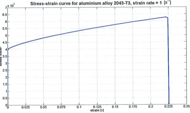
For the failure of the material the Damage Initial and Damage Evolution options of ABAQUS are used. The following figure 2 shows exemplarily the identified behaviour for the aluminium alloy 2043-T3, which is a standard material for aircraft structures.
Figure 2. Material behaviour for aluminium alloy 2043-T3.
MODEL VALIDATION VIA CRASH ONTO RIGID WALL
The goal for application of the aircraft models is to represent the realistic impact load for a crash on a structure. Accordingly a validation of the model is carried out by computing the Ft-curve with respect to published existing approaches, see France (1988).
Therefore a crash of the aircraft model on a rigid wall is carried out. The wall is fixed for all degrees of freedom at its reference node. At the beginning of the simulation all nodes of the aircraft have an initial impact velocity of 77 m/sec. The velocity is defined based on the impulse of the existing Ft-curve considering the mass of the model.
The interaction between all model parts including also self-contact is defined by the General Contact
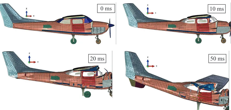
Figure 3. Deformation for Crash onto Rigid Wall at 0, 10, 20 and 30 ms .
The simulation showed that only the frontal part of the aircraft is mainly damaged. The engine is partially perforating the intermediate wall to the passenger cabin. Further a bending of the wings can be observed leading to a small impact at their tip. The back part of the fuselage and also the tail shows almost no damage.
As mentioned above, Ft-curve is evaluated and compared with the published available data of France (1988), see figure 4. Before the comparison the simulation result is smoothed by two approaches (Straight Average Method and Low-Pass-filter) to eliminate numerical artefacts. The comparison shows that the simulation correlates with respect to its characteristics with the existing Ft-curve. The maximum load occurs with a value of about 6 MN at 10 ms and is caused by the impact of the engine at the front.
Figure 4. Ft-curve for Cessna 210 with velocity of 80 m/sec.
0 ms
10 ms
20 ms
50 ms
CRASH SIMULATION OF IMPACT ONTO CONCRETE WALL
FE-Model Setup Concrete Wall
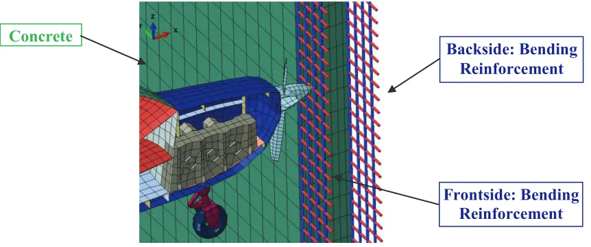
Three concrete walls are modelled with same dimensions (length and height), but with different thickness 40, 60 and 80 cm. The model consists of hexahedron elements with reduced integration, where 8 elements are used over the thickness. In figure 5 the model setup for the concrete wall is shown.
Figure 5. Model setup for concrete wall - isometric view of cross section.
The two bending reinforcement layers are modelled via beam elements at the front and the back side of the wall. The model does not include any shear reinforcement. The interaction between concrete and reinforcement is defined via the Embedded Element Option of ABAQUS, which automatically defines kinematic couplings for each beam node with the surrounding nodes of the solid concrete elements. The wall is fixed for all nodes at the vertical and horizontal edges.
Concrete and Reinforcement Material Models
ABAQUS provides beside standard material models as the Drucker-Prager approach the Concrete Damage Plasticity model. Initially this specific model for concrete was developed by Lubliner (1989). The approach enables the modelling of concrete or other brittle material which could include embedded reinforcements. It covers setups with monotonic and dynamic loading scenarios. The material definition is separated in tension and compression. For each of these states the plasticity and damage behaviour must
be described. The damage part specifies thereby the reduction of Young’s modulus.
The material behaviour is defined by the CEB FIP Model Code 90 (1993) using the stress-strain-curve. The following figure 6 shows the behaviour of selected C35/40 concrete material under dynamic compression and tension loading with strain rate of 0.1 s-1.
Concrete
Backside: Bending
Reinforcement
Figure 6. Material behaviour defined by Concrete Damage Plasticity Model.
The Johnson-Cook material approach is used too to simulate the reinforcement of the concrete walls. The parameters are defined for Bst420, which is typically used for the setup of buildings.
Impact Simulation and Results
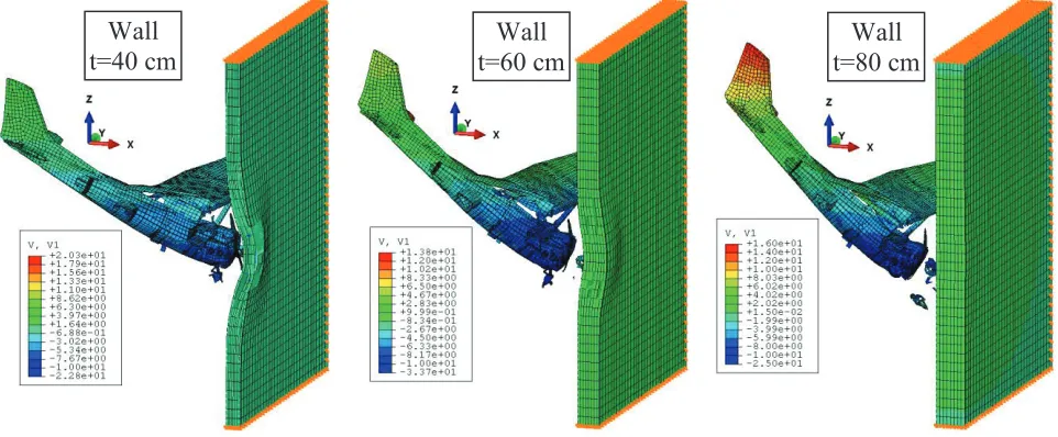
For the impact the aircraft is positioned in front of the wall. The interaction between all model parts including also self-contact is defined by General Contact algorithm. Altogether three walls with different thickness are impacted with a velocity of 77 m/sec. Figure 7 shows the deformed model state for all three setups at the end of the analysis.
Figure 7. Model state at the end of impact action for three concrete walls.
It can be seen that the aircraft caused a significant, although localised, damage on the first wall with 40 cm thickness. A smaller damage can be observed for the second one (60 cm thickness). For both walls the starting of a punching cone can be determined but no perforation can be observed. Evaluating the setup with 80 cm almost no damage can be observed.
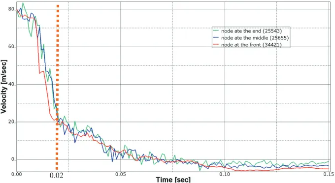
For more detailed evaluation the velocity-time-curve of three points along the aircraft is computed for the setup with 40 cm thickness, see figure 8.
Compression
behavior
behavior
Tensile
Wall
t=40 cm
Wall
t=60 cm
Figure 8. Evaluation points of Cessna 210 for computation of vt-curve.
As it can be seen by the vt-curve, see figure 9, the aircraft is finally stopped. The main damage of the wall appears at about 20 ms. All three nodes show an oscillation of the vt-curve due to the interaction with other parts of the airplane. Finally all nodes show a small negative velocity representing a rebound effect at the end of the impact.
Figure 9. Vt-curve for impact of Cessna 210 via concrete wall with 40 cm thickness
CONCLUSION
The generated FE-model of the Cessna 210 enables the impact simulation on civil engineering structures. Computing with the model the Ft-curve for a crash on a rigid wall a good correlation to existing data can be determined, which represents somehow a validation of the model and its properties.
Using the integral simulation approach realistic scenario can be represented covering three dimensional geometric effects and the interaction between aircraft and structure. Here the crash onto three different concrete walls with the thickness of 40, 60 and 80 cm is carried out. For the walls of 40 and 60 cm damage can be observed but no perforation of the aircraft is determined. Contrary thereto the wall with a thickness of 80 cm shows almost no damage.
Based on the simulation results the application of the generated FE-model for impact analysis is shown. As the investigated walls represent with their material properties and the percentage of reinforcement only a general setup no assessment with respect to real civil engineering structures can be made.
REFERENCES
ABAQUS (2013), Software Package - Release 6.12-1, Dassault Systemes, France, www.3DS.com
HyperMesh (2013), Software Package - Release 12, Altair Engineering, Inc., USA, www.altair.com France, (1988). “Règles de conception et de construction de génie civil des centrales nucléaires.”,
Rep.RCC. G 85-Rev.2, Electricité de France, France.
Johnson, G. R., et al. (1983). “A constitutive model and data for materials subjected to large strain, high strain rates and high temperature”, Proceedings Int. Symposium Ballistics, pp. 541-547.
Lubliner, J., et al. (1989). “A Plastic-Damage Model for Concrete” International Journal of Solid and Structures, Vol. 25, pp. 299-329.