ISSN(Online): 2319-8753 ISSN (Print) : 2347-6710
I
nternational
J
ournal of
I
nnovative
R
esearch in
S
cience,
E
ngineering and
T
echnology
(A High Impact Factor, Monthly Peer Reviewed Journal)
Vol. 5, Issue 2, February 2016
Suppressing the Fault Current Level in a
Distribution System with Distributed
Generation Units Using an Active Type SFCL
K. Ramesh Kumar 1, Y. Babu Yadav 2
P.G. Student, Department of EEE, KUPPAM Engineering College, Kuppam, Chittoor, A.P, India1
Associate Professor, Department of EEE, KUPPAM Engineering College, Kuppam, Chittoor, A.P, India 2
ABSTRACT: This paper presents power distribution system with distributed generation (DG) units, its fault current and induced overvoltage under abnormal conditions should be taken into account severely. In consideration that applying superconducting fault current limiter (SFCL) may be a good solution. In this paper, the effects of a voltage compensation type active SFCL on them are studied through theoretical derivation and simulation. The active SFCL is composed of an core superconducting transformer and a five level diode converter. The magnetic field in the air-core can be controlled by adjusting the converters output current, and then the active SFCLs equivalent impedance can be regulated for current limitation and possible overvoltage suppression. During this process, in view of the changes in the locations of the DG units connected to the system, the DG unit’s injection capacities and the fault positions, the active SFCLs current-limiting and overvoltage suppressing characteristics are both simulated in MATLAB. The simulation results show that the active SFCL can play a vital role in restraining the fault current and it can contribute to avoiding damage on the relevant distribution equipment and improve the systems safety and reliability.
KEYWORDS: Distribution system, Distributed Generation (DG), Short-circuit current, voltage compensation type active Superconducting Fault Current Limiter (SFCL)
I. INTRODUCTION
Due to increased consumption demand and high cost of natural gas and oil, Distributed Generation (DG), which generates electricity from many small energy sources, is becoming one of main components in distribution systems to feed electrical loads [1]–[3]. The introduction of DG into a distribution network may bring lots of advantages, such as emergency backup and peak shaving. However, the presence of these sources will lead the distribution network to lose its radial nature, and the fault current level will increase. Besides, when a single-phase grounded fault happens in a distribution system with isolated neutral, over voltages will be induced on the other two healthy phases, and in consideration of the installation of multiple DG units, the impacts of the induced over voltages on the distribution network’s insulation stability and operation safety should be taken into account seriously. Aiming at the mentioned technical problems, applying superconducting fault current limiter (SFCL) may be a feasible solution. For the application of some type of SFCL into a distribution network with DG units, a few works have been carried out, and their research scopes mainly focus on current-limitation and improvement of protection coordination of protective devices [4]–[6].
ISSN(Online): 2319-8753 ISSN (Print) : 2347-6710
I
nternational
J
ournal of
I
nnovative
R
esearch in
S
cience,
E
ngineering and
T
echnology
(A High Impact Factor, Monthly Peer Reviewed Journal)
Vol. 5, Issue 2, February 2016
view of the changes in the locations of the DG units connected into the distribution system, the DG units’ injection capacities and the fault positions, the current limiting and overvoltage-suppressing characteristics of the active SFCL are investigated in detail.
II. THEORETICAL ANALYSIS
1. Structure and Principle of the Active SFCL
As shown in Fig. 1(a), it denotes the circuit structure of the single-phase voltage compensation type active SFCL, which is composed of an air-core superconducting transformer and Five level diode converter. Ls1, Ls2 are the self-inductance of two superconducting windings, and Ms is the mutual self-inductance. Z1 is the circuit impedance and Z2 is the load impedance. Ld and Cd are used for filtering high order harmonics caused by the converter. Since the voltage-type converter’s capability of controlling power exchange is implemented by regulating the voltage of AC side, the converter can be thought as a controlled voltage source Up. By neglecting the losses of the transformer, the active SFCL’s equivalent circuit is shown in Fig. 1(b).
In normal (no fault) state, the injected current (I2) in the secondary winding of the transformer will be controlled to keep a certain value, where the magnetic field in the air-core can be compensated to zero, so the active SFCL will have no influence on the main circuit. When the fault is detected, the injected current will be timely adjusted in amplitude or phase angle, so as to control the superconducting transformer’s primary voltage which is in series with the main circuit, and further the fault current can be suppressed to some extent.
Below, the suggested SFCL’s specific regulating mode is explained. In normal state, the two equations can be achieved.
ISSN(Online): 2319-8753 ISSN (Print) : 2347-6710
I
nternational
J
ournal of
I
nnovative
R
esearch in
S
cience,
E
ngineering and
T
echnology
(A High Impact Factor, Monthly Peer Reviewed Journal)
Vol. 5, Issue 2, February 2016
I2 = Us_Ls1/Ls2/(Z1 + Z2)k, where k is the coupling coefficient and it can be shown as k = Ms/ √Ls1Ls2. Under fault condition (Z2 is shorted), the main current will rise from I1 to I1f , and the primary voltage will increase to U1f .
The current-limiting impedance ZSFCLcan be controlled in:
According to the difference in the regulating objectives of I2, there are three operation modes: 1) Making I2 remain the original state, and the limiting impedance
ZSFCL−1 = Z2 (jωLs1)/(Z1 + Z2 + jωLs1). 2) Controlling I2 to zero, and ZSFCL−2 = jωLs1. 3) Regulating the phase angle of I2 to make the angle
Difference between ˙Us and jωMs I˙2 be 180◦ By setting jωMs I2 = −c Us, and ZSFCL−3 = cZ1/(1 − c) +jωLs1/(1− c).
The air-core superconducting transformer has many merits, such as absence of iron losses and magnetic saturation, and it has more possibility of reduction in size, weight and harmonic than the conventional iron-core superconducting transformer [11], [12]. Compared to the iron-core, the air-core can be more suitable for functioning as a shunt reactor because of the large magnetizing current [13], and it can also be applied in an inductive pulsed power supply to decrease energy loss for larger pulsed current and higher energy transfer efficiency [14], [15]. There is no existence of transformer saturation in the air-core, and using it can ensure the linearity of ZSFCL well.
2. Applying the SFCL Into a Distribution Network With DG
ISSN(Online): 2319-8753 ISSN (Print) : 2347-6710
I
nternational
J
ournal of
I
nnovative
R
esearch in
S
cience,
E
ngineering and
T
echnology
(A High Impact Factor, Monthly Peer Reviewed Journal)
Vol. 5, Issue 2, February 2016
In order to calculate the overvoltages induced in the other two phases (phase B and phase C), the symmetrical component method and complex sequence networks can be used, and the coefficient of grounding G under this condition can be expressed as G = −1.5m/(2 + m) ± j√3/2, where m =X0/X1, and X0 is the distribution network’s zero-sequence reactance, X1 is the positive-sequence reactance [16]. Further, the amplitudes of the B-phase and C-phase over voltages can be
Where UAN is the phase-to-ground voltage’s root mean square (RMS) under normal condition.
As shown in Fig. 3, it signifies the relationship between the reactance ratio m and the B-phase overvoltage. It should be pointed out that, for the distribution system with isolated neutral-point, the reactance ratio m is usually larger than four. Compared with the condition without SFCL, the introduction of the active SFCL will increase the power distribution network’s positive-sequence reactance under fault state. Since X0/(X1 + ZSFCL) < X0/X1, installing the active SFCL can help to reduce the ratio m. And then, from the point of the view of applying this suggested device, it can lower the overvoltage’s amplitude and improve the system’s safety and reliability. Furthermore, taking into account the changes in the locations of the DG units connected into the distribution system, the DG units’ injection capacities and the fault positions, the specific effects of the SFCL on the fault current and overvoltage may be different, and they are all imitated in the simulation analysis.
ISSN(Online): 2319-8753 ISSN (Print) : 2347-6710
I
nternational
J
ournal of
I
nnovative
R
esearch in
S
cience,
E
ngineering and
T
echnology
(A High Impact Factor, Monthly Peer Reviewed Journal)
Vol. 5, Issue 2, February 2016
III. SIMULATION STUDY
1. Simulation Circuit Analysis
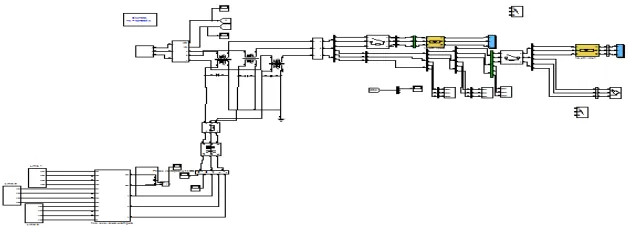
Fig 4: Simulation Circuit of SFCL with DG units
For purpose of quantitatively evaluating the current-limiting and overvoltage-suppressing characteristics of the active SFCL, the distribution system with DG units and the SFCL, as shown in Fig. 2 is created in MATLAB. The SFCL is installed in the behind of the power supply Us, and two DG units are included in the system, and one of them is fixedly installed in the Bus B (named as DG1). For the other DG, it can be installed in an arbitrary position among the Buses C–E (named as DG2). The model’s main parameters are shown in Table I. To reduce the converter’s design capacity making the SFCL switch to the mode 2 after the fault is detected, and the detection method is based on measuring the main current’s different components by Fast Fourier Transform (FFT) and harmonic analysis
2. Overvoltage-Suppressing Characteristics of the SFCL
Supposing that the injection capacity of each DG is about 80% of the load capacity (load 1), and the fault location is k1 point (phase-A is shorted), and the fault time is t = 0.2 s, the simulation is done when the DG2 is respectively installed in the Buses C, D, and E, and the three cases are named as case I, II, and III. Fig. 4 shows the SFCL’s overvoltage- suppressing characteristics and the waveforms with and without the SFCL are both listed. For the cases I, II, and III, the overvoltage’s peak amplitude without SFCL will be respectively 1.14, 1.23, 1.29 times of normal value, and once the active SFCL is applied, the corresponding times will drop to 1.08, 1.17, and 1.2.
ISSN(Online): 2319-8753 ISSN (Print) : 2347-6710
I
nternational
J
ournal of
I
nnovative
R
esearch in
S
cience,
E
ngineering and
T
echnology
(A High Impact Factor, Monthly Peer Reviewed Journal)
Vol. 5, Issue 2, February 2016
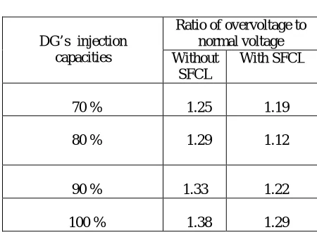
During the study of the influence of the DG’s injection capacity on the overvoltage’s amplitude, it is assumed that the adjustable range of each DG unit’s injection capacity is about 70% ∼ 100% of the load capacity (load 1), the two DG units are located in the Buses B and E, and the other fault conditions are unchanged, Table II shows the overvoltage’s amplitude characteristics under this background.
Along with the increase of the DG’s injection capacity, the overvoltage will be accordingly rise, and once the injection capacity is equal or greater than 90% of the load capacity, the overvoltage will exceed acceptable limit (1.3 times). Nevertheless, if the active SFCL is put into use, the limit-exceeding problem can be solved effectively.
Table 2
DG’s injection capacities
Ratio of overvoltage to normal voltage Without
SFCL
With SFCL
70 % 1.25 1.19
80 % 1.29 1.12
90 % 1.33 1.22
100 % 1.38 1.29
Table 2: Overvoltage’s amplitude characteristics under different injection capacities of DG units
Fig. 4. Voltage characteristics of the Bus-A under different locations of DG units.
V
o
lt
ag
e(
ISSN(Online): 2319-8753 ISSN (Print) : 2347-6710
I
nternational
J
ournal of
I
nnovative
R
esearch in
S
cience,
E
ngineering and
T
echnology
(A High Impact Factor, Monthly Peer Reviewed Journal)
Vol. 5, Issue 2, February 2016
3. Current-Limiting Characteristics of the SFCL
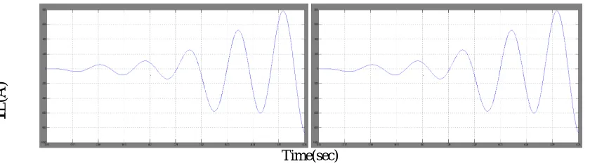
By observing the voltage compensation type active SFCL’s Installation location, it can be found out that this device’s current-limiting function should mainly reflect in suppressing the line current through the distribution transformer. Thereupon, to estimate the most serious fault characteristics, the following conditions are designed: the injection capacity of each DG is about 100% of the load capacity (load 1), and he two DG units are separately installed in the Buses B and E. Moreover, the three-phase fault occurs at k1, k2, and k3 points respectively, and the fault occurring time is t = 0.2 s. Hereby, the line current characteristics are imitated. As shown in Fig. 5, it indicates the line current waveforms of the active SFCL when the three-phase short circuit occurs at k3 point. After installing the active SFCL, the first peak value of the fault currents (iAf, iBf, iCf ) can be limited to 2.51 kA, 2.69 kA, 1.88 kA, respectively, in contrast with 3.62 kA, 3.81 kA, 2.74 kA under the condition without SFCL. The reduction rate of the expected fault currents will be 30.7%, 29.4%, 31.4%, respectively.
Fig. 6 shows the SFCL’s current-limiting performances when the fault location is respectively k1 point t (selecting the phase-A current for an evaluation). Along with the decrease of the distance between the fault location and the SFCL’s installation position, the current-limiting ratio will increase from 12.7% (k1 point) to 21.3% (k2 point). Besides, as one component of fault current, natural response is an exponential decay DC wave, and its initial value has a direct relationship with fault angle. In other words, corresponding to different initial fault angles, the short-circuit current’s Peak amplitudes will be distinguishing. Through the application of the active SFCL, the influence of initial fault angle on the peak amplitude of the A-phase short-circuit current is analyzed in Fig. 5, where the fault location is k3 point. It can be seen that, under the conditions with and without the SFCL, the short circuit current’s peak amplitude will be smallest when the fault angle is about 130◦. At this fault angle, the power distribution system can immediately achieve the steady transition from normal state to fault state.
Time (sec)
Fig.5 Active SFCL’s current-limiting performances at k3 fault locations.
Time(sec)
Fig. 6 Line current waveforms when the three-phase short-circuit occurs at k3 point. (a) Without SFCL (b) with SFCL
IL
(A
)
I
L
(A
ISSN(Online): 2319-8753 ISSN (Print) : 2347-6710
I
nternational
J
ournal of
I
nnovative
R
esearch in
S
cience,
E
ngineering and
T
echnology
(A High Impact Factor, Monthly Peer Reviewed Journal)
Vol. 5, Issue 2, February 2016
V. CONCLUSION
In this paper, the application of the active SFCL into in a power distribution network with DG units is investigated. For the power frequency overvoltage caused by a single-phase grounded fault, the active SFCL can help to reduce the overvoltage’s amplitude and avoid damaging the relevant distribution equipment. The active SFCL can as well suppress the short-circuit current induced by a three-phase grounded fault effectively, and the power system’s safety and reliability can be improved. Moreover, along with the decrease of the distance between the fault location and the SFCL’s installation position, the current-limiting performance will increase.
In recently years, more and more dispersed energy sources, such as wind power and photovoltaic solar power, are installed into distribution systems. Therefore, the study of a coordinated control method for the renewable energy sources and the SFCL becomes very meaningful, and it will be performed in future.
REFERENCES
[1] S. Conti, “Analysis of distribution network protection issues in presence of dispersed generation,” Elect. Power System”. Res., vol. 79, no. 1, pp. 49–56, Jan. 2009. [2] A. S. Emhemed, R. M. Tumilty, N. K. Singh, G. M. Burt, andJ. R. McDonald, “Analysis of transient stability enhancement of LV connected induction micro generators by using resistive-type fault current limiters,” IEEE Trans. Power Syst., vol. 25, no. 2, pp. 885–893, May 2010.
[3] S.-Y. Kim and J.-O. Kim, “Reliability evaluation of distribution network with DG considering the reliability of protective devices affected by SFCL,” IEEE Trans. Appl. Supercond., vol. 21, no. 5, pp. 3561–3569,Oct. 2011.
[4] S. A. A. Shahriari, A. Yazdian, and M. R. Haghifam, “Fault current limiter allocation and sizing in distribution system in presence of distributed generation,” in Proc. IEEE Power Energy Soc. Gen. Meet., Calgary, AB, Canada, Jul. 2009.
[5] S. Hemmati and J. Sadeh, “Applying superconductive fault current limiter to minimize the impacts of distributed generation on the distribution protection systems,” in Proc. Int. Conf. Environ. Electr. Eng., Venice, Italy, May 2012.
[6] S.-H. Lim, J.-S. Kim, M.-H. Kim, and J.-C. Kim, “Improvement of protection coordination of protective devices through pplication of a SFCL in a power distribution system with a dispersed generation,” IEEE Trans. Appl. Supercond., vol. 22, no. 3, p. 5601004, Jun. 2012.
[7] L. Chen, Y. Tang, J. Shi, and Z. Sun, “Simulations and experimental analyses of the active superconducting fault current limiter,” Phys. C, vol. 459, no. 1/2, pp. 27–32, Aug. 2007.
[8] L. Chen, Y. Tang, J. Shi, Z. Li, L. Ren, and S. Cheng, “Control strategy for three-phase four-wire PWM converter of integrated voltage compensation type active SFCL,” Phys. C, vol. 470, no. 3, pp. 231–235, Feb. 2010.
[9] L. Chen, Y. J. Tang, J. Shi, L. Ren, M. Song, S. J. Cheng, Y. Hu, and X. S. Chen, “Effects of a voltage compensation type active superconducting fault current limiter on distance relay protection,” Phys. C, vol. 470, no. 20, pp. 1662–1665, Nov. 2010.
[10] J. Wang, L. Zhou, J. Shi, and Y. Tang, “Experimental investigation of an active superconducting current controller,” IEEE Trans. Appl. Supercond., vol. 21, no. 3, pp. 1258–1262, Jun. 2011.
[11] H. Yamaguchi and T. Kataoka, “Stability analysis of air-core superconducting power transformer,” IEEE Trans. Appl. Supercond., vol. 7, no. 2, pp. 1013–1016, Jun. 1997.
[12] H. Yamaguchi, T. Kataoka, H. Matsuoka, T. Mouri, S. Nishikata, and Y. Sato, “Magnetic field and electromagnetic force analysis of 3-phase aircore superconducting power transformer,” IEEE Trans. Appl. Supercond., vol. 11, no. 1, pp. 1490–1493, Mar. 2001.
[13] M. Song, Y. Tang, N. Chen, Z. Li, and Y. Zhou, “Theoretical analysis and experiment research of high temperature superconducting air core transformer,” in Proc. Int. Conf. Electr. Mach. Syst., Wuhan, China, pp. 4394–4397,Oct. 2008.
[14] R. Wu, Y. Wang, Z. Yan, W. Luo, and Z. Gui, “Design and experimental realization of a new pulsed power supply based on the energy transfer between two capacitors and an HTS air-core pulsed transformer,” IEEE Trans. Plasma Sci., vol. 41, no. 4, pp. 993–998, Apr. 2013.
[15] R. Wu, Y. Wang, Z. Yan, Z. He, and L. Wang, “Simulation and experimental investigation of an inductive pulsed power supply based on the head-to-tail series model of an HTS air-core pulsed transformer,” IEEE Trans. Appl. Supercond., vol. 23, no. 4, p. 5701305, Aug. 2013.
[16] S. Chen, W. Wang, and P. Yang, “Effects of current-limiting inductor on power frequency over voltages in transmission line,” Power Syst. Technol., vol. 34, no. 3, pp. 193–196, Mar. 2010.
BIOGRAPHY
.
K.Ramesh Kumar received B.Tech degree Form (Electrical & Electronics Engineering) in SITAMS, Chittoor in 2013. Studying M.Tech (power Electronics) from KEC, Kuppam, JNTUA, his areas of interest in Power Electronics& SFCL.Feb 2016.