AT&T
DEFINITY
Communications
®
System Generic 1
and
System 75 and System 75 XE
TO ORDER COPIES OF THIS MANUAL
Call: AT&T Customer Information Center on 1-800-432-6600 In Canada Call 1-800-255-1242
Write: AT&T Customer Information Center
2855 North Franklin Road P.O. Box 19901
Indianapolis, IN 46219-1385
While reasonable efforts were made to ensure that the information in this document was complete and accurate at the time of printing, AT&T can assume no responsibility for errors. Changes or corrections to the information in this document may be incorporated into future reissues.
Published by
The AT&T Documentation Development Organization
Contents
CHAPTER 1. INTRODUCTION
Purpose Organization
CHAPTER 2. FUNCTIONAL DESCRIPTION
Overview
Voice Management Data Management Network Services System Management
Hospitality Services (V3 or G1) Call Management (V3 or G1)
1-1 1-1 1-2 2-1 2-1 2-1 2-3 2 - 1 8 2 - 2 8 2 - 3 1 2 - 3 2
CHAPTER 3. FEATURE DESCRIPTIONS
Overview
AAR/ARS Partitioning (V3 or G1) Abandoned Call Search (V3 or G1) Abbreviated Dialing
Agent Call Handling (V3 or G1) AP Demand Print (V1, V2, or V3) Attendant Auto-Manual Splitting Attendant Call Waiting
Attendant Control of Trunk Group Access
Attendant Direct Extension Selection With Busy Lamp Field Attendant Direct Trunk Group Selection
Attendant Display Attendant Recall
Attendant Release Loop Operation
Audio Information Exchange (AUDIX) Interface (V3 or G1) Authorization Codes (V3 or G1)
Automatic Alternate Routing (V2, V3, or G1)
Automatic Callback
Automatic Call Distribution (V3 or G1) Automatic Circuit Assurance (V2, V3, or G1) Automatic Incoming Call Display (V2, V3, or G1) Automatic Route Selection (V1)
Automatic Route Selection (V2, V3, or G1) Automatic Wakeup (V3 or G1)
Basic Call Management System (G1)
3-79 3-82 3-97 3-101 3-103 3-110 3-119 3-125 Bridged Call Appearance—Multi-Appearance Voice Terminal
Bridged Call Appearance—Single-Line Voice Terminal (G1) Busy Verification of Terminals and Trunks (V2, V3, or G1) Call By Call Service Selection (G1)
Call Coverage
Call Forwarding All Calls (V1)
Call Forwarding All Calls (V2, V3, or G1) Call Park
Call Pickup Class of Service Code Calling Access Conference—Attendant Conference—Terminal Consult
Coverage Callback
Coverage Incoming Call Identification
Customer-Provided Equipment (CPE) Alarm (XEV2, XEV3, or G1) Data Call Setup
Data Hot Line (V2, V3, or G1) Data-Only Off-Premises Extensions Data Privacy 3-142 3-149 3-159 3-164 3-175 3-187 3-190 3-194 3-198 3-228 3-231 3-234 3-235 3-236 3-237 3-238 3-239 3-241 3-249 3-251 3-253 3-255 3-257 3-260 Data Restriction
DCS Attendant Direct Trunk Group Selection (V2, V3, or G1) DCS Attendant Display (V2, V3, or G1)
DCS Automatic Callback (V2, V3, or G1)
DCS Automatic Circuit Assurance (V2, V3, or G1)
DCS Busy Verification of Terminals and Trunks (V2, V3, or G1) DCS Call Forwarding All Calls (V2, V3, or G1)
DCS Call Waiting (V2, V3, or G1) DCS Distinctive Ringing (V2, V3, or G1) DCS Leave Word Calling (V2, V3, or G1)
DCS Multi-Appearance Conference/Transfer (V2, V3, or G1) DCS Trunk Group Busy/Warning Indication (V2, V3, or G1)
3-263 3-265 3-267 3-269 3-271 3-273 3-274 3-276 3-278 3-280 3-281 Dial Access to Attendant
Dial Plan
Digital Multiplexed Interface (V2, V3, or G1)
Direct Department Calling and Uniform Call Distribution Direct Inward Dialing
Direct Outward Dialing Distinctive Ringing
Do Not Disturb (V3 or G1)
DS1 Trunk Service (V2, V3, or G1) EIA Interface (V2, V3, or G1)
Emergency Access to the Attendant (V3 or G1) Facility Busy Indication
Facility Restriction Levels and Traveling Class Marks (V2, V3, or G1) Facility Test Calls
Forced Entry of Account Codes (V2, V3, or G1) Generalized Route Selection (G1)
3-283 3-284 3-287 3-289 3-297 3-298 3-299 3-302 3-306 3-311 3-314 3-318 3-320 3-324 3-326 3-329 Go to Cover
Hold
Hot Line Service Hunting
Individual Attendant Access (V2, V3, or G1)
Information System Network (ISN) Interface (V2, V3, or G1) Integrated Directory
Integrated Services Digital Network—Primary Rate Interface (G1) Intercept Treatment
Intercom—Automatic Intercom—Dial
Inter-PBX Attendant Calls (V2, V3, or G1) Intraflow and Interflow (V3 or G1)
Last Number Dialed Leave Word Calling Line Lockout
Loudspeaker Paging Access
Loudspeaker Paging Access—Deluxe (G1) Manual Message Waiting
Manual Originating Line Service Manual Signaling
Modem Pooling
Move Agents From CMS (V3 or G1)
Multi-Appearance Preselection and Preference Multiple Listed Directory Numbers
Music-on-Hold Access Names Registration (G1) Network Access—Private Network Access—Public
Night Service—Hunt Group (V3 or G1) Night Service—Night Console Service Night Service—Night Station Service
Night Service—Trunk Answer From Any Station Night Service—Trunk Group (V3 or G1)
Off-Premises Station
Permanent Switched Calls (V2, V3, or G1) Personal Central Office Line
Personalized Ringing (V2, V3, or G1) Power Failure Transfer
Priority Calling
Privacy—Attendant Lockout Privacy—Manual Exclusion
Property Management System Interface (V3 or G1) Queue Status Indications (V3 or G1)
Recall Signaling
Recent Change History (G1) Recorded Announcement
Recorded Telephone Dictation Access Remote Access
Report Scheduler and System Printer (G1) Restriction—Controlled
Restriction—Miscellaneous Terminal Restriction—Miscellaneous Trunk Restriction—Toll/Code
Restriction—Voice Terminal—Inward
Restriction—Voice Terminal—Manual Terminating Line Restriction—Voice Terminal—Origination
Restriction—Voice Terminal—Outward Restriction—Voice Terminal—Termination Ringback Queuing
Ringer Cutoff
Rotary Dialing (V2, V3, or G1) Send All Calls
Senderized Operation
Service Observing (V3 or G1)
Single-Digit Dialing and Mixed Station Numbering (V3 or G1) SMDR Account Code Dialing
Station Message Detail Recording Straightforward Outward Completion Subnet Trunking (V2, V3, or G1) System Measurements
System Status Report (V2, V3, or G1) Temporary Bridged Appearance
Ten-Digit to Seven-Digit Conversion (G1) Terminating Extension Group
Time of Day Routing (G1) Through Dialing
Timed Reminder Touch-Tone Dialing Transfer
Trunk Group Busy/Warning Indicators to Attendant Trunk Identification By Attendant (V2, V3, or G1) Trunk-to-Trunk Transfer
Uniform Dial Plan (V2, V3, or G1)
Voice Message Retrieval (V2, V3, or G1) Voice Terminal Display
3-545 3-593 3-594 3-598 3-601 3-603 3-605 3-611 3-615 3-623 3-624 3-626 3-627 3-628 3-630 3-632 3-633 3-637 3-642
CHAPTER 4. SYSTEM PARAMETERS
Overview Feature Administration Feature Access System Capacities 4-1 4-1 4-1 4-4 4-9 5-1 6-1 7-1 8-1
CHAPTER 5. REFERENCES
CHAPTER 6. GLOSSARY
CHAPTER 7. ABBREVIATIONS AND ACRONYMS
Figures
Figure 2-1. Figure 2-2. Figure 2-3. Figure 2-4. Figure 2-5. Figure 2-6. Figure 3-1. Figure 3-2. Figure 3-3. Figure 3-4. Figure 3-5. Figure 3-6. Figure 3-7. Figure 3-8. Figure 3-9. Figure 3-10. Figure 3-11. Figure 3-12. Figure 3-13. Figure 3-14. Figure 3-15. Figure 3-16. Figure 3-17. Figure 3-18. Figure 3-19. Figure 3-20. Figure 3-21. Figure 3-22. Figure 3-23.System Data Communications Configuration System Networking Configurations
Digital Communications Protocol Frame Structure Typical ETN Configuration
Typical Distributed Communications System Main/Satellite/Tributary Configuration
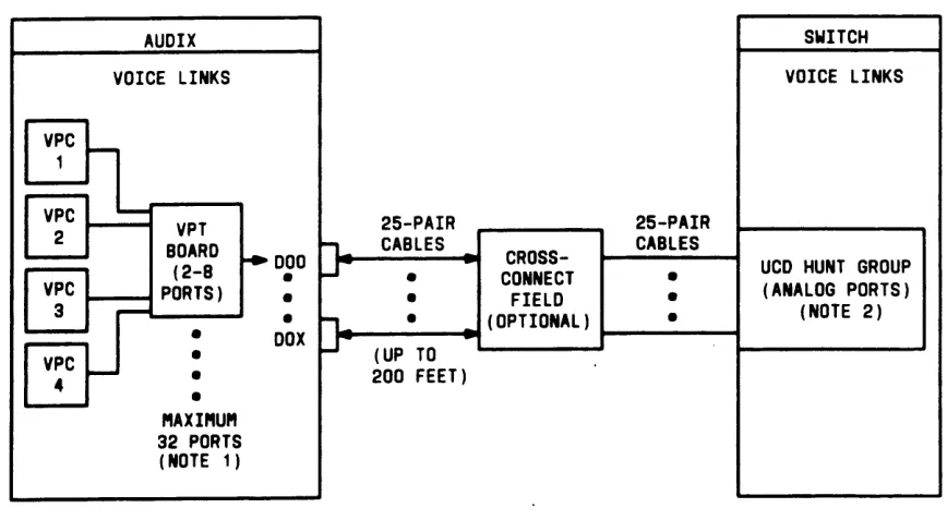
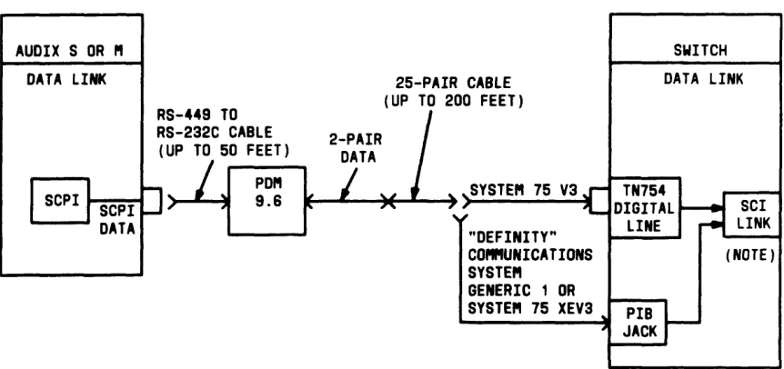
Voice Connections—DEFINITY Generic 1 to AUDIX Data Link Connection—AUDIX
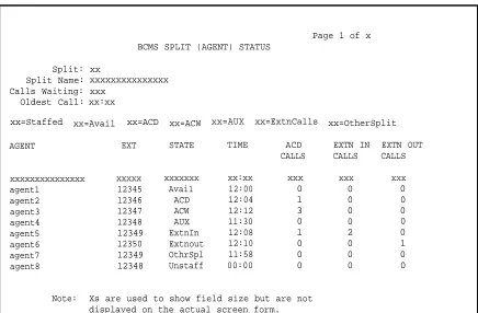
Simplified AUDIX Arrangement Simplified DCS AUDIX Arrangement Split Agent Status Report
System Status Report Agent Time Report Agent Daily Report Split Time Interval Report Split Daily Interval Report System Time Report System Daily Report Trunk Time Report Trunk Daily Report
Call By Call Service Selection Example
Screen Form to Schedule Usage Allocation Plans Example Screen Form Used to Assign Actual Usage Allocation Plans Example
Blank Screen Form to Provide Treatment of Incoming Call By Call Service Selection Calls Example
Example of Screen Form Used for Implementing CORs
Screen Form Used to Explain Miscellaneous Restriction Groups System to ISN Connectivity
ISDN-PRI Private Network Configuration ISDN-PRI Public Network Configuration
Figure 3-24. Figure 3-25. Figure 3-26. Figure 3-27. Figure 3-28. Figure 3-29. Figure 3-30. Figure 3-31. Figure 3-32. Figure 3-33. Figure 3-34. Figure 3-35. Figure 3-36. Figure 3-37. Figure 3-38. Figure 3-39. Figure 3-40. Figure 3-41. Figure 3-42. Figure 3-43. Figure 3-44. Figure 3-45. Figure 3-46. Figure 3-47. Figure 3-48. Figure 3-49. Figure 3-50. Figure 3-51.
SID/ANI to Host Configuration (G1) Interworking Example
Outbound Call Management Configuration With Cluster Controller and Host
Recent Change History Report
Report Scheduler Screen Form (With Immediate Print Interval) Report Scheduler Screen Form (With Scheduled Print Interval) Report Scheduler Screen Form (With Deferred Print Interval) Screen Form Used To Change Report Scheduler
Screen Form Used To List Report Scheduler Information
3-368 3-370 3-445 3-492 3-504 3-505 3-505 3-506 3-508 3-554 3-555 3-556 3-557 SMDR Data Format—TELESEER SMDR Unit (V1)
SMDR Data Format—TELESEER SMDR Unit (V2 or V3) SMDR Data Format—TELESEER SMDR Unit (G1)
SMDR Data Format—TELESEER SMDR Unit With ISDN (G1) SMDR Direct Output Format From System to Printer (V1) SMDR Direct Output Format From System to Printer (V2 or V3) SMDR Direct Output Format From System to Printer (G1) ISDN SMDR Direct Output Format From System to Printer (G1) SMDR Direct Output Format From System to 94A Local Storage Unit System or 3B2 CDRU (V1)
SMDR Direct Output Format From System to 94A Local Storage Unit System or 3B2 CDRU (V2)
SMDR Direct Output Format From System to 94A Local Storage Unit System or 3B2 CDRU (V3)
SMDR Direct Output Format From System to 94A Local Storage Unit System or 3B2 CDRU (G1)
ISDN SMDR Direct Output Format From System to 94A Local Storage Unit System or 3B2 CDRU (G1)
SMDR 59-Character Direct Output Format (V1) SMDR 59-Character Direct Output Format (V2 or V3) SMDR 59-Character Direct Output Format (G1)
24-Word ISDN Unformatted SMDR Record Format (G1) 24-Word ISDN Expanded SMDR Record Format (G1) Date Record Format to 94A LSU or 3B2 CDRU
Figure 3-52. Figure 3-53. Figure 3-54. Figure 3-55. Figure 3-56. Figure 3-57. Figure 3-58. Figure 3-59. Figure 3-60. Table 2-A. Table 3-A. Table 3-B. Table 3-C. Table 3-D. Table 3-E. Table 3-F. Table 3-G. Table 3-H. Table 3-I.
Date Record Format to Printer
Date Record Format to TELESEER SMDR Unit
Example of a TELESEER SMDR Unit Summary Report Example of a TELESEER SMDR Unit Account Code Detail Report
Example of a TELESEER SMDR Unit Activity Report Example of a TELESEER SMDR Unit Selection Report Screen Form Used for Implementing Time of Day Routing Screen Form Used for Time of Day Routing Example Uniform Dial Plan Example
Tables
Packet Switching Protocols ARS Routing Table
Call Progress Messages for Keyboard Dialing BCC Assignment
Assignment of BCC Based on Information Transfer Capability Software Port Correlations
Condition Codes
Condition Code Override Matrix
Network Specific Facility to INS Mapping
Ten-Digit to Seven-Digit Conversion Table Example
CHAPTER 1. INTRODUCTION
Purpose
Organization
CHAPTER 1. INTRODUCTION
This manual provides a technical description of the system features and parameters for the following systems:
CHAPTER 1. INTRODUCTION
● DEFINITY® Communications System, Generic 1 ● System 75 (V1, V2, and V3)
● System 75 XE (V2 and V3).
Information in this document applies to all versions and types of the listed systems unless
specifically noted otherwise in parentheses.
Also, unless otherwise noted, any information noted as V2 or V3 also applies to System 75 XE V2 or System 75 XE V3, respectively.
The terms "DEFINITY Generic 1" and "G1" refer to the DEFINITY Communications System Generic 1.
Purpose
This manual, along with AT&T System 75—System Description, 555-200-200, the AT&T System 75 XE—System Description, 555-201-200, and the DEFINITY Communications System Generic
1—System Description, 555-204-200, is intended to serve as an overall reference for the
planning, operation, and administration stages of the system. It is also intended to be used with AT&T System 75—Implementation, 555-200-650 for V1, 555-200-651 for V2, 555-200-652 for V3, and DEFINITY Communications System—Implementation, 555-204-654 for DEFINITY Generic 1, for software initialization and subsequent changes in feature assignments.
This issue replaces all previous issues of this document. The reason for reissue is to include enhancements to the DEFINITY Communications System Generic 1, as well as other miscellaneous information, including a description of the Ringer Cutoff feature.
The new features added to DEFINITY Generic 1 include the following:
● Basic Call Management System ● Loudspeaker Paging Access—Deluxe ● Names Registration
● Outbound Call Management
CHAPTER 1. INTRODUCTION
Other important additions include enhancements to the Property Management System Interface feature and enhancements to the Attendant Direct Extension Selection With Busy Lamp Field feature.
Organization
The rest of this manual is divided into seven chapters as follows:
●
●
●
●
●
●
●
Chapter 2—Functional Description—Provides a general description of the functions and services provided with the system. These functions and services are divided into six groups. The six groups are Voice Management, Data Management, Network Services, System Management, Hospitality Services, and Call Management. Each group of functions and services is described separately and includes a list of associated features. The listed features are fully described in Chapter 3 of this manual.
Chapter 3—Feature Descriptions—Provides a detailed description of the features associated with Voice Management, Data Management, Network Services, System Management, Hospitality Services, and Call Management. These feature descriptions are arranged in alphabetical order, regardless of function area.
Chapter 4—System Parameters—Provides information relating to overall system characteristics and capacities. This chapter includes items that must be considered when planning for system implementation.
Chapter 5—References—Provides a list of reference documentation. A brief description of each document is included.
Chapter 6—Glossary—Provides a glossary for the entire manual.
Chapter 7—Abbreviations and Acronyms—Provides a list of abbreviations and acronyms used in this manual.
Overview
Voice Management
Overview
Voice Management Features
Data Management
Overview
Data Networking
Data Management Features
CHAPTER 2. FUNCTIONAL DESCRIPTION
Data Communications Protocols and Interfaces Overview
Electronic Industries Association (EIA) AT&T
International Telegraph and Telephone Consulative Committee (CCITT) International Business Machines
Network Services
Overview
Network Services Features Private Network Configurations
Electronic Tandem Network (ETN)
Distributed Communications System (DCS) (V2, V3, or G1) Main/Satellite/Tributary
Trunking
System Management
Overview
System Management Features System Administration
Remote Administration
Customer Services Support Organization (CSSO)
Hospitality Services (V3 or G1)
Overview
Hospitality Services Features
2 - 3 1 2 - 3 1 2 - 3 1 2 - 3 2 2 - 3 2 2 - 3 2
Call Management (V3 or G1)
Overview
Figures
Figure 2-1. System Data Communications Configuration Figure 2-2. System Networking Configurations
Figure 2-3. Digital Communications Protocol Frame Structure Figure 2-4. Typical ETN Configuration
Figure 2-5. Typical Distributed Communications System Figure 2-6. Main/Satellite/Tributary Configuration
2-6 2-9 2-13 2-21 2-22 2-25
2-16
Tables
CHAPTER 2. FUNCTIONAL DESCRIPTION
CHAPTER 2. FUNCTIONAL DESCRIPTION
Overview
This chapter describes the features, functions, and services provided with the system. These features, functions, and services are divided into six groups: Voice Management, Data Management, Network Services, System Management, Hospitality Services, and Call Management. Each group of functions and services is described separately and the description includes a list of associated features. The listed features are fully described in Chapter 3 of this manual.
Voice Management
Overview
The many Voice Management features available with the system allow the individual needs of everyone in the system to be met. As the individual’s needs change, the assigned features can also be changed. The Voice Management features provide important services with benefits such as saving time and making calling more convenient.
Voice Management Features
The following features are associated with Voice Management. Abbreviated Dialing
AP Demand Print
Attendant Auto-Manual Splitting Attendant Call Waiting
Attendant Control of Trunk Group Access
Attendant Direct Extension Selection With Busy Lamp Field Attendant Direct Trunk Group Selection
Attendant Display Attendant Recall
Attendant Release Loop Operation
Audio Information Exchange (AUDIX) Interface (V3 or G1) Authorization Codes (V3 or G1)
Automatic Callback
Automatic Incoming Call Display (V2, V3, or G1)
Bridged Call Appearance—Multi-Appearance Voice Terminal Bridged Call Appearance—Single-Line Voice Terminal (G1) Busy Verification of Terminals and Trunks (V2, V3, or G1) Call By Call Service Selection (G1)
Call Coverage
CHAPTER 2. FUNCTIONAL DESCRIPTION
Call Park Call Pickup
Call Waiting Termination
Centralized Attendant Service (V2, V3, or G1) Class of Restriction
Class of Service Code Calling Access Conference—Attendant Conference—Terminal Consult
Coverage Callback
Coverage Incoming Call Identification Dial Access to Attendant
Dial Plan
Direct Department Calling and Uniform Call Distribution Direct Inward Dialing
Direct Outward Dialing Distinctive Ringing
Emergency Access to the Attendant (V3 or G1) Facility Busy Indication
Forced Entry of Account Codes (V2, V3, or G1) Go To Cover
Hold
Hot Line Service Hunting
Individual Attendant Access (V2, V3, or G1) Integrated Directory
Intercept Treatment Intercom—Automatic Intercom—Dial
Inter-PBX Attendant Calls (V2, V3, or G1) Last Number Dialed
Leave Word Calling Line Lockout
Loudspeaker Paging Access
Loudspeaker Paging Access—Deluxe (G1) Manual Message Waiting
Manual Originating Line Service Manual Signaling
Multi-Appearance Preselection and Preference Multiple Listed Directory Numbers
Music-on-Hold Access
Night Service—Hunt Group (V3 or G1) Night Service—Night Console Service Night Service—Night Station Service
Night Service—Trunk Answer From Any Station Night Service—Trunk Group (V3 or G1)
CHAPTER 2. FUNCTIONAL DESCRIPTION
Power Failure Transfer Priority Calling
Privacy—Attendant Lockout Privacy—Manual Exclusion Recall Signaling
Recorded Announcement
Recorded Telephone Dictation Access Remote Access
Restriction—Controlled
Restriction—Miscellaneous Terminal Restriction—Miscellaneous Trunk Restriction—Toll/Code
Restriction—Voice Terminal—Inward
Restriction—Voice Terminal—Manual Terminating Line Restriction—Voice Terminal—Origination
Restriction—Voice Terminal—Outward Restriction—Voice Terminal—Termination Ringback Queuing
Ringer Cutoff
Rotary Dialing (V2, V3, or G1) Send All Calls
Senderized Operation
Single-Digit Dialing and Mixed Station Numbering (V3 or G1) SMDR Account Code Dialing
Straightforward Outward Completion Temporary Bridged Appearance Terminating Extension Group Through Dialing
Timed Reminder Touch-Tone Dialing Transfer
Trunk Group Busy/Warning Indicators to Attendant Trunk Identification by Attendant (V2, V3, or G1) Trunk-to-Trunk Transfer
Voice Message Retrieval (V2, V3, or G1) Voice Terminal Display.
Data Management
Overview
CHAPTER 2. FUNCTIONAL DESCRIPTION
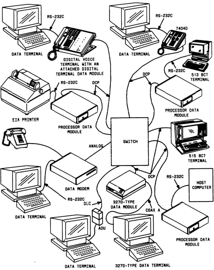
The physical connection can be through a digital data module or analog modem.
The system provides the customer with options for selecting data modules (or data-like devices such as a Data Line Circuit [DLC] [V2, V3, G1]) for Terminal Dialing. Also, customers can use data modules without Terminal Dialing with host computers, printers, or other such applications. Computer file transfer at a speed rate of 64 kbps is possible with the Modular Processor Data Module (MPDM) and the Modular Trunk Data Module (MTDM).
The family of data modules also includes a Processor Data Module (PDM), a Digital Terminal Data Module (DTDM), a Modular Data Module (MDM), a Trunk Data Module (TDM), and a 3270 Data Module. The data modules are generally more versatile than modems, operate at faster data rates, and provide additional features.
The 7404D voice terminal has a built-in data module that allows the voice terminal to control and be connected to a data terminal. Data calls can be originated or disconnected using the key pad of the attached data terminal. Voice calls can be made or received while a data call is in progress. The 7406D and 7407D voice terminals have the same data feature functions as the 7404D, through the use of an optional base containing a data module.
The AT&T Personal Terminal 510D, which operates in alphanumeric and graphics character set mode, provides the equivalent of a Model 7405D voice terminal equipped with a DTDM, a 513 Business Communications Terminal (BCT), and a Digital Display Module.
The 515 BCT has the same video display and keyboard features as the 513 BCT. In addition, it provides voice terminal functions and the functional equivalent of a Digital Display Module. The 510D terminal or 515 BCT provides an all-digital interface with the system. Through its built-in Electronic Industries Association (EIA) RS-232C interface, the 515 BCT can connect to other data equipment.
The DLC, which provides eight ports to connect user’s asynchronous EIA RS-232C interface to Data Terminal Equipment (DTE), can be used as an alternative to DTDM or PDM.
CHAPTER 2. FUNCTIONAL DESCRIPTION
The 3270 Data Module is available in the following three models:
●
●
●
3270T (Terminal)—Connects to a Category A 3270-type terminal, such as the IBM* 3278 Information Delivery System. The 3270T Data Module must connect through the switch to a 3270C (Controller) Data Module.
3270A (Asynchronous)—Provides the same function as the 3270T Data Module. It also allows the 3270-type terminal to emulate a Digital Equipment Corporation VT100† or an AT&T asynchronous terminal.
3270C (Controller)—Connects an IBM 3274 or 3276 cluster controller to the switch. A 3270C Data Module can contain as many as eight ports.
The system supports digital-to-digital, digital-to-analog, analog-to-digital, and analog-to analog data calls. For data calls, the user can access the system through these digital or analog data endpoints. Digital data endpoints are data modules and associated data equipment, 510D terminals or 515 BCTs, data channels (used for remote System Access Terminals [SATs] [V1, V2, and V3] or DEFINITY Manager I terminals [G1], and Station Message Detail Recording [SMDR]), and/or the Applications Processor (AP) interface (inside the system). Analog data endpoints are modems (or acoustic coupled modems) and associated data equipment connected to the system through analog lines or trunks.
The system supports a Digital Communications Protocol (DCP). This protocol provides framing, control, and signaling for each of two information channels. Only one channel is used for voice-only or data-only applications. Both channels are used for simultaneous voice and data transmission. Simultaneous voice and data information can be transmitted on calls to or from a 510D terminal or 515 BCT, a 7403D or 7405D voice terminal with a DTDM, a 7404D with its built-in data module, and a 7406D or 7407D with an optional data module base. Calls to or from other equipment are either voice-only or data-only.
Data Networking
Data networking connects two or more data endpoints. The system is a highly reliable, centralized switch that provides switched access between endpoints. Typical data communications configurations for the system are shown in Figure 2-1.
Switched access allows one terminal to connect to any number of devices. Therefore, more effective use of data equipment is obtained than with dedicated (hard-wired) links. Switched access also reduces the need for duplicated (dedicated) equipment.
The system uses twisted-pair standard building wiring and 8-pin modular wall jacks. Each wall jack is a single outlet that can handle simultaneous voice and data information.
*
†
Registered trademark of International Business Machines Corporation
CHAPTER 2. FUNCTIONAL DESCRIPTION
CHAPTER 2. FUNCTIONAL DESCRIPTION
The digital switch, data modules, DCP, twisted-pair wiring, modular wall jacks, and switched data features give the system its unique capabilities. These capabilities merge the business office data processing and telecommunications functions into a single system.
Generally, data networks are either local area networks, extended networks, or combinations of both. The two networks and their implementation within the system are defined as follows:
●
●
Local Area Networks
The system provides this capability by connecting communication devices that are physically located within a local-area or campus-like environment. These include conventional, semi-intelligent, and intelligent data terminals, personal computers, host computers, and virtually any device with the proper communications interface.
The centralized network provides circuit switched paths using twisted-pair building cable that extends to the endpoints. Since the business office equipment can access multiple data systems, the data equipment and applications can be used more productively. The system also provides several data-related features that are easy to use and that contribute toward expedient use of the system and its networking capabilities.
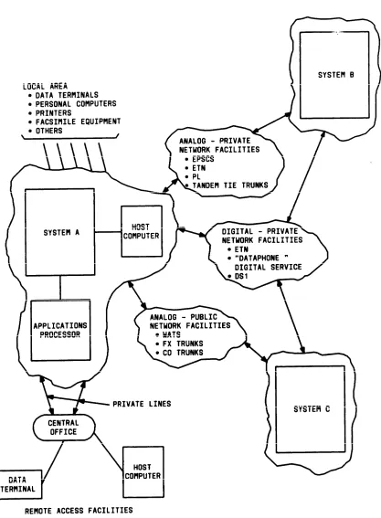
Extended Networks
Extended networks mainly provide connections between the system and other distant switches, including remote access facilities. Through use of remote access facilities, a local terminal can access remote host computers. Also, remote terminals can access either local computer facilities or other remote computer facilities. Extended networks are constructed of analog or digital facilities and can be either public or private. Typical networking configurations are shown in Figure 2-2.
Public networks include: —
— — — — — —
Local central office (CO) switching extended through direct distance dialing Foreign exchange (FX) central office trunking
Wide Area Telecommunications Service (WATS) MEGACOM™ Telecommunications Service MEGACOM 800 Telecommunications Service Software Defined Network (SDN)
ACCUNET® Digital Service. Private networks include:
CHAPTER 2. FUNCTIONAL DESCRIPTION
— — — — —
Distributed Communications System (DCS) Electronic Tandem Network (ETN)
Enhanced Private Switched Communications Service (EPSCS) Private line (PL)
CHAPTER 2. FUNCTIONAL DESCRIPTION
CHAPTER 2. FUNCTIONAL DESCRIPTION
Data Management Features
The following features are associated with Data Management: Data Call Setup
Data Hot Line (V2, V3, or G1) Data-Only Off-Premises Extensions Data Privacy
Data Restriction
Digital Multiplexed Interface (V2, V3, or G1) DS1 Tie Trunk Service (V2, V3, or G1) EIA Interface (V2, V3, or G1)
Information System Network (ISN) Interface Modem Pooling
PC/PBX Connection
Permanent Switched Calls (V2, V3, or G1) Uniform Call Distribution (UCD).
Data Communications Protocols and Interfaces
Overview
A protocol is a set of conventions or rules that governs how data is transmitted and received. The rules generally cover such subjects as the following:
●
●
●
●
●
Physical interface Mechanical interface Electrical interface Framing
Error detection and control.
Communications protocols are designed to meet the transmission requirements for specific data exchange and data communications equipment. These communications protocols are sponsored by a national or international organization or a major corporation. The system equipment, Applications Processor (AP), and communications processing software provide the following protocols:
●
●
●
●
RS-232C RS-449 RS-366
CHAPTER 2. FUNCTIONAL DESCRIPTION
●
●
●
●
●
Teletypewriter (TTY) Modes
Digital Communications Protocol (DCP) BX.25 Packet Switching
International Telegraph and Telephone Consultative Committee (CCITT) V.35 Binary Synchronous Communications (Bisync).
Electronic Industries Association (EIA)
RS-232C
This protocol is widely used for short distance and low-speed applications such as data terminals and modems connecting data terminals. The data link consists of a 25-conductor cable. The conductors are used for data-link control and timing, as well as for transmitting and receiving signals. Data-link control is accomplished by handshake signaling between the transmit and receive devices. Data speeds are limited to 19.2 kbps or less.
The RS-232C protocol provides two interface connectors. The female side connector is known as data communications equipment (DCE). The male side connector is known as data terminal equipment (DTE). Data equipment manufacturers design either the DCE or DTE interface into their products. Products such as modems, data service units (DSUs), Digital Terminal Data Modules (DTDMs), and Processor Data Modules (PDMs) have a built-in DCE interface. Products such as some types of multiplexers, data terminals, printers, computer ports, and Trunk Data Modules (TDMs) have a built-in DTE interface. Modular Data Modules (MDMs) can be configured as either DCE or DTE.
The maximum cable length recommended by EIA for the RS-232C protocol is 25 feet (15 meters). However, practical applications have shown that the cable length can be much greater. Factors limiting cable length include transmission speed, cable capacitance, and nearness of noise sources such as fluorescent lights or electric generators. Each application should be considered separately.
RS-449
This protocol allows longer cables than the RS-232C. Maximum cable lengths for various data speeds are as follows:
●
●
●
●
CHAPTER 2. FUNCTIONAL DESCRIPTION
The RS-449 protocol is provided as a communications link interface on the AP. This standard uses a 37-conductor cable. The AP RS-449 interface contains unbalanced driver/receivers that also permit interconnection to the RS-232C interface when used with a 37- to 25-pin cable adapter. Since the AP RS-449 interface is compatible with the RS-232C protocol, it also is limited to the same maximum 19.2 kbps data rate.
RS-366
The RS-366 communications protocol specifies the standards for interfacing computers to automatic calling units (ACUs). This permits a computer to originate data calls over a switched telephone network. The AP provides one RS-366 interface for each six RS-232C interface ports.
AT&T
Standard Serial Interface (SSI)
The SSI communications protocol is used with the 500-series Business Communications Terminals (BCTs) and 400-series printers. The interface operates full-duplex, in synchronous mode, at 56 kbps, and over 24-gauge standard building cable at distances up to 5000 feet (1524 meters). Cable connections are made through the 8-pin modular-type connectors.
Teletypewriter (TTY) Modes
The AP EIA RS-232C interface ports support the TTY protocol. This protocol is implemented as software within the AP’s EIA terminal or port subsystem. The protocol permits each port to operate in either the transparent or TTY mode.
● Transparent Mode
When operating in the transparent mode, the ports pass American Standard Code for Information Interchange (ASCII) characters between the AP and terminal device unchanged. Incoming characters can be echoed back to the terminal device as they are received. However, no recognition of control characters is provided. The BREAK character is the only special character that can be recognized. The following options are available:
— — — — — —
Parity (enable and disable, even and odd) Data rate—less than 300 up through 19,200 bps Stop bits—1, 1-1/2, or 2 bits
CHAPTER 2. FUNCTIONAL DESCRIPTION
Some of these options are pre-coded by the applications software and cannot be changed by the voice terminal user.
● TTY Mode
When operating in the TTY mode, the EIA interface port acts as both the pre-processor and post-pre-processor between the terminal and the AP applications software. In addition to all options listed under the transparent mode, several ASCII control characters are recognized.
A variety of control (delay) options are available to interface with different types of EIA-compatible printers. The ASCII characters DEL and NUL are used for fill (delay) characters. Termination options are provided for line control of modems and ACUs. The TTY mode also provides several mapping options.
The AP applications software determines the mode (transparent or TTY) and the options within each mode that are implemented per EIA channel. The methods for selecting EIA channel parameters are provided through option designation display forms or by default. When display forms are provided, they are an integral part of the applications software.
Digital Communications Protocol (DCP)
The DCP is used by the system’s digital switch, digital voice terminals, data modules, the 510D terminal, and the 515 BCT. This protocol permits simultaneous voice and data over the same communications link to the switch.
The DCP consists of a 160-kbps, 4-wire serial data link that operates full-duplex over standard twisted-pair building cable. For data-only transmission, the maximum cable length is 5000 feet (1524 meters). When voice and data transmission is carried over the same data link, as when a 510D terminal, 515 BCT, or a DTDM is used, the cable length is limited by the voice transmission distance.
The DCP sends digitized voice and digital data in frames. Each frame consists of four fields or channels (see Figure 2-3). The first field is a unique 3-bit framing pattern that defines the frame boundary. The second field is a 1-bit control or signaling channel between the digital switch and digital data endpoint. The third and fourth fields are two independent information (I) channels. The information channels are 8 bits each and are used to send digitized voice or digital data.
FRAMING INFORMATION INFORMATION FRAMING
● ● ●
FIELD SIGNAL #1 #2 FIELD ● ● ● DCP FRAME
CHAPTER 2. FUNCTIONAL DESCRIPTION
There are 8000 frames per second. Therefore, the bit rate available is 8 kbps for the signaling channel and 64 kbps for the information channel. The digital switch routes each information channel independently so that simultaneous voice and data can be completed to different destinations.
The full capacity of the information channels (64 kbps) is available for digitized voice. Data terminals typically operate at speeds from below 300 bps up to 19.2 kbps, asynchronous or synchronous. The DCP uses data modules to map the data terminal data into a 64-kbps information channel.
The framing rate of 8000 per second and 8 bits per information channel is consistent with other telecommunication systems such as the T1 carrier. This minimizes potential conversion problems when interfacing to different digital facilities.
BX.25 Packet Switching Protocol
The BX.25 protocol implements the international standard for packet switching. It is a multilayered protocol. (Layering is a structuring of specific protocol functions [for example, error detection and correction] that are grouped together as a unique layer or level.)
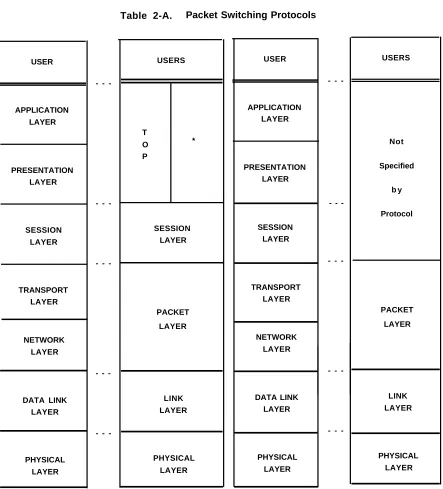
The BX.25 protocol is similar to the CCITT X.25 protocol and, from a user perspective, is compatible with the standard. The BX.25 protocol has three layers which are not specified for the X.25 protocol. These layers are the Application, Presentation, and Session layers. The Application and Presentation layers (see Table 2-A) are defined in the Transaction Oriented Protocol (TOP) of the BX.25.
The TOP is a high-level protocol, intended to standardize communications between transaction-oriented systems. Transaction-oriented communications involve communication of small messages or requests describing a single unit of work, which may result in a reply being sent back to the originating system. The Session layer is intended to establish, manage, and terminate sessions for use by higher level protocols or, in some cases, by user applications directly. Other differences between X.25 and BX.25 are as follows:
●
●
●
The X.25 protocol specifies network standards only; the BX.25 protocol places requirements on the user interface as well.
The X.25 protocol provides for datagram services while the BX.25 protocol does not. Datagram service has not been implemented within the continental United States. The X.25 protocol leaves the users in a point-to-point environment to develop their own solutions to the following areas of potential conflict, while the BX.25 protocol provides solutions:
— — —
CHAPTER 2. FUNCTIONAL DESCRIPTION
Basic elements of the Application and Presentation layers must be user-defined under both protocols. Table 2-A shows the relationship and similarity between the BX.25 and X.25 protocols.
CHAPTER 2. FUNCTIONAL DESCRIPTION USER APPLICATION LAYER PRESENTATION LAYER SESSION LAYER TRANSPORT LAYER NETWORK LAYER DATA LINK LAYER PHYSICAL LAYER
-Table 2-A. Packet Switching Protocols
USERS T O * P SESSION LAYER PACKET LAYER LINK LAYER PHYSICAL LAYER USER APPLICATION LAYER PRESENTATION LAYER SESSION LAYER TRANSPORT LAYER NETWORK LAYER DATA LINK LAYER PHYSICAL LAYER -USERS Not Specified b y Protocol PACKET LAYER LINK LAYER PHYSICAL LAYER
CHAPTER 2. FUNCTIONAL DESCRIPTION
International Telegraph and Telephone Consulative Committee (CCITT)
X.25 Packet Switching Protocol
The CCITT is one of three divisions of the International Telecommunications Union, an agency of the United Nations. The standards set by the CCITT generally deal with public networks. Two series of standards or recommendations specifically deal with data transmission:
●
●
The V-series provides recommendations for data transmission over analog or voice telephone networks.
The X-series provides recommendations for data transmission over digital networks. The V-series includes the V.10, V.11, V.24, V.28, and V.35. Also, V.26, V.27, and V.28 are modem recommendations for 2400, 4800, and 9600 bps, respectively.
V.10 and V.11 are the equivalent to the EIA RS-423 and RS-422.
V.24 provides the definitions for all interchange circuits that cross the DTE/DCE interface. V.28 defines a set of electrical characteristics that are compatible with RS-232C.
V.35 provides the constant current interface for 48-kbps operation.
The X.25 protocol is the CCITT recommendation for implementing the International Standards Organizations Reference Model of Open Systems Interconnection which is the international model for packet switching networks. This is a bit-oriented, layered-type protocol. The transport, network, data link, and physical layers (levels) are defined functionally by the CCITT.
The X.25 protocol specifies network requirements and procedures to provide the user interface for a packet switching network. Typically, users generate low-speed asynchronous data. The X.25 software segments this data into packets, adds framing and routing information, and queues the packets into a buffer memory. User data packets, along with the added framing bits, are then transmitted over high-speed carriers. This permits efficient and dynamic sharing of these high-speed data links.
The X.25 protocol provides the communications links between multiple APs.
International Business Machines
Binary Synchronous Communications (Bisync)
Bisync is a character-oriented protocol that provides data transfer, error detection, and error correction. It is widely used for interactive data communications networks.
CHAPTER 2. FUNCTIONAL DESCRIPTION
The Bisync protocol is implemented partly in hardware and partly in software. The physical or hardware level consists of the AP and its associated communications line controller. The line controller has an RS-232C and an RS-449 communications port. Both ports can be used for connection to Bisync-type networks.
The Bisync protocol can be used in either point-to-point or multipoint data link configurations. These network configurations can be either switched or dedicated lines. Generally, the data link operates in half-duplex, synchronous mode at 2.4, 4.8, or 9.6 kbps. Either the ASCII or the Extended Binary Coded Decimal Interchange Code (EBCDIC) can be used.
The AP uses the Bisync protocol in providing 2780/3780 and 3270 terminal emulation features.
Network Services
Overview
Network Services allows a group of switches (consisting of DEFINITY Generic 1, System 75, and/or other systems) to be configured to meet the communications needs of a medium- to large-size corporation. Possible arrangements include an Electronic Tandem Network (ETN), Distributed Communications System (DCS), and Main/Satellite/Tributary. Each is briefly described in this chapter.
Do not assume that the system has any capabilities other than those explicitly stated herein.
Refer to Network and Data Services—Reference, 555-025-201, for differences between this system and other AT&T systems. (Check DEFINITY Communications System Generic 1 and
System 75 Documentation Guide, 555-200-010, for the availability of this document.)
Network Services Features
The following features are associated with Network Services: AAR/ARS Partitioning (V3 or G1)
Automatic Alternate Routing (V2, V3, or G1) Automatic Circuit Assurance (V2, V3, or G1) Automatic Route Selection (V1)
Automatic Route Selection (V2, V3, or G1)
DCS Alphanumeric Display for Terminals (V2, V3, or G1) DCS Attendant Control of Trunk Group Access (V2, V3, or G1) DCS Attendant Direct Trunk Group Selection (V2, V3, or G1) DCS Attendant Display (V2, V3, or G1)
DCS Automatic Callback (V2, V3, or G1)
DCS Automatic Circuit Assurance (V2, V3, or G1)
DCS Busy Verification of Terminals and Trunks (V2, V3, or G1) DCS Call Forwarding All Calls (V2, V3, or G1)
CHAPTER 2. FUNCTIONAL DESCRIPTION
DCS Multi-Appearance Conference/Transfer (V2, V3, or G1) DCS Trunk Group Busy/Warning Indication (V2, V3, or G1)
Facility Restriction Levels and Traveling Class Marks (V2, V3, or G1) Generalized Route Selection (G1)
Integrated Services Digital Network—Primary Rate Interface (G1) Network Access—Private
Network Access—Public Off-Premises Station
Subnet Trunking (V2, V3, or G1)
Ten-Digit to Seven-Digit Conversion (G1) Time of Day Routing (G1)
Uniform Dial Plan (V2, V3, or G1).
Private Network Configurations
A private network is a configuration of trunk and switching facilities dedicated to the use of a business or organization. It may have as few as two switches or it may have hundreds of switches located throughout the country. (A DEFINITY Generic 1 or System 75 DCS, however, is limited to 64 switches.) Although they normally serve moderate to heavy calling between locations, the following configurations make it possible for organizations of all sizes to realize the benefits of a private network.
●
●
●
ETN—Serves the needs of customers with many locations in a large geographic area. This configuration provides for calling between locations without accessing toll facilities.
DCS—Serves the needs of customers with several locations in a small or large geographic area. A Distributed Communications System appears as a single switch with respect to certain features.
Main/Satellite/Tributary—Serves the needs of customers with a few locations in a small geographic area.
The system also can be used within a Tandem Tie Trunk Network (TTTN). A TTTN is a non-hierarchical network of tie trunks interconnecting three or more switches. User dialing into each switch in the call’s path is required. That is, the user at one switch dials the trunk access code for a tie trunk group to another switch, receives dial tone from that switch, and then dials another trunk access code to reach another switch. When dial tone is received from the final (desired) switch, the user dials the desired extension number.
Electronic Tandem Network (ETN)
CHAPTER 2. FUNCTIONAL DESCRIPTION
The system can serve as an ETN tandem switch. However, it’s capabilities as an ETN tandem switch are limited.
Within an ETN, each location is identified by a unique private network office code, called an RNX. An RNX never matches an Area Code, so 640 possible RNXs are available for each ETN. After accessing the ETN, the user simply dials the RNX plus the desired extension number, for a total of seven digits.
Public network office codes (NXXs) are unique within an Area Code, whereas RNXs are unique within an ETN. RNXs are assigned when the ETN is established and, for convenience, may match NXXs (although this is not always possible). When Direct Inward Dialing (DID) is provided by the local central office, the extension numbers (last four digits of the number) will match. Network Inward Dialing (NID) is the ETN equivalent of DID and can be provided without DID.
CHAPTER 2. FUNCTIONAL DESCRIPTION
Figure 2-4. Typical ETN Configuration
Distributed Communications System (DCS) (V2, V3, or G1)
A DCS is a cluster of private communications switches (nodes), interconnected among several geographic locations. These switches can be either a System 75, System 85, DEFINITY Generic 1, DEFINITY Generic 2.1, or DIMENSION® PBX. If all nodes are System 75s or DEFINITY Generic 1s, the DCS can have as many as 64 nodes. This maximum number of nodes decreases slightly if the DCS includes a System 85 or DIMENSION PBX. An attribute of a DCS configuration that distinguishes it from other networks is that it appears as a single switch with respect to certain features. This provides simplified dialing procedures between locations, as well as the convenience of using some of the system’s features between locations. DCS is particularly attractive if there is frequent interlocation calling.
CHAPTER 2. FUNCTIONAL DESCRIPTION
A DCS can consist of all endpoints. That is, each node in the DCS may be directly connected by data links and voice channels with every other node in the DCS. In this case, System 75 or DEFINITY Generic 1 can serve as all nodes.
Some of the applications of the DCS configuration are as follows:
● In a "campus environment" that has two or more separate buildings and the nodes
are connected by local cable
● In a larger area such as a city, several states, or even the entire country, where the
nodes are separated by distances too great for local cable and may be connected to different central offices.
A DCS has the property of "transparency" with respect to inside calling and some features. Transparency is the ability of the system, from the user’s standpoint, to operate across several nodes in the same way it does at the local node. This allows users to dial from any terminal to any other terminal within the DCS without regard for which nodes are involved. Likewise, transparency allows certain voice features to be used across nodes.
CHAPTER 2. FUNCTIONAL DESCRIPTION
Some voice features have transparency in a DCS configuration. The following voice features have unique aspects in a DCS environment and are described in detail in Chapter 3.
●
●
●
●
●
●
●
●
●
●
●
●
●
●
●
DCS Alphanumeric Display for Terminals
DCS Attendant Call Waiting (described under DCS Call Waiting) DCS Attendant Control of Trunk Group Access
DCS Attendant Direct Trunk Group Selection DCS Attendant Display
DCS Automatic Callback
DCS Automatic Circuit Assurance
DCS Busy Verification of Terminals and Trunks DCS Call Forwarding All Calls
DCS Call Waiting—Termination (described under DCS Call Waiting) DCS Distinctive Ringing
DCS Leave Word Calling
DCS Multi-Appearance Conference/Transfer
DCS Priority Calling (described under DCS Call Waiting) DCS Trunk Group Busy/Warning Indication.
Abbreviated Dialing and Last Number Dialed also have transparency in a DCS configuration. These features operate the same in a DCS as they do at a single switch.
A DCS cluster can consist of up to 64 nodes. Since the Applications Processor (AP), Audio Information Exchange (AUDIX), and the Call Management System (CMS) each require the same data link facilities as a node, each of these included in the system reduces the number of available data links which, depending on the system configuration, may reduce the maximum number of nodes.
DCS Message Hopping lets a DCS message route through an intermediate node without tandeming an associated trunk call. This is accomplished through the use of hop channels. The system provides Message Hopping through up to two hops. For a detailed description of DCS Message Hopping, see the AT&T System 75—Application Notes—Distributed
Communications System, 555-209-003.
CHAPTER 2. FUNCTIONAL DESCRIPTION
Certain feature capabilities are unique to a particular type of node (for example, a System 75 or DEFINITY Generic 1 endpoint node). Therefore, a detailed feature description should be consulted for each type of node.
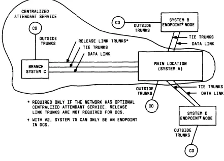
The Centralized Attendant Service (CAS) feature can be used as an advantage in DCS networks where all attendants are at one node. CAS reduces traffic volume on interconnecting tie trunks caused by incoming attendant-seeking calls at the endpoint nodes. A V1 or V2 System 75 cannot serve as the main location for CAS attendants. A V3 System 75 or a DEFINITY Generic 1 can serve as the main location for CAS attendants. Centralized Attendant Service capabilities are given in detail in Chapter 3.
A call from one DCS node to another DCS node can redirect through the Call Coverage feature. The Coverage tone, which indicates that the call has redirected to Coverage, is heard by the calling party at the distant node. However, the call cannot redirect to a distant node. The principal and the covering user must be located at the same node. An exception to this is when CAS is used. However, DCS transparency is not provided for the CAS call. Only the release link trunk name will be displayed at the attendant console, not the name or extension of the user on the remote switch that is covering to the attendant.
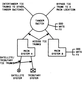
Main/Satellite/Tributary
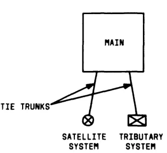
Figure 2-6 shows a Main/Satellite/Tributary configuration. It can function independently or serve as an Electronic Tandem Network (ETN) access arrangement. For a Main/Satellite configuration, attendant positions and public network trunk facilities are concentrated at the Main, and calls to or from satellite locations pass through the Main. To a caller outside the Main/Satellite complex, the system appears to be a single switch with one Listed Directory Number. This is accomplished with the optional Uniform Dial Plan software.
Tributary and Satellite locations are similar except that a Tributary has one or more attendant positions and its own Listed Directory Number.
System 75 Version 1 can serve as a Satellite or Tributary. Version 2, Version 3, or DEFINITY Generic 1 can serve as a Main, Satellite, or Tributary.
CHAPTER 2. FUNCTIONAL DESCRIPTION
Figure 2-6. Main/Satellite/Tributary Configuration
Trunking
Trunking is the use of communications links to interconnect two switching systems, such as connecting the switch to a local central office or to another switch. These links, called trunks, can be grouped together in Trunk Groups when all the trunks in the group perform the same function. This grouping simplifies administration since the required service characteristics (parameters) are assigned to the group rather than to each trunk. Grouping also simplifies call processing. Calls requiring a trunk are routed to the appropriate trunk group and an idle trunk, if available, is selected from the group.
The following types of trunk groups can be used with the system:
●
●
●
●
●
●
Auxiliary—Provides internal trunk applications for features such as Loudspeaker Paging and Music-on-Hold.
Central Office (CO)—Provides a link with the local CO for calls except Direct Inward Dialing (DID) calls.
Direct Inward Dialing (DID)—Provides a link with the local CO.
DS1 Tie Trunk—Provides for two types of digital tie trunk interfaces: Voice-Grade DS1 and Alternate Voice/Data (AVD) DS1 tie trunks. The Voice-Grade DS1 tie trunks are an alternative to 4-wire analog E&M tie trunks and may be used to interface with other properly-equipped switching systems. AVD DS1 tie trunks permit alternate voice and data calling between a System 75 or DEFINITY Generic 1 and a System 85 or DEFINITY Generic 2. DS1 tie trunks can also be used with Release Link trunks for Centralized Attendant Service, and can be used with MEGACOM Service.
Foreign Exchange (FX)—Provides a link with a CO other than the local CO.
CHAPTER 2. FUNCTIONAL DESCRIPTION
and ACCUNET and calls destined for different interexchange carriers can be processed.
●
●
Tie and Release Link (V2, V3, and G1 only)—Provide a link with another private switching system for calls between the systems. Release link trunks are used only with Centralized Attendant Service. Tie trunks are used on calls to or from the following:
— — —
—
A Private Branch Exchange (PBX)
An Electronic Tandem Network (ETN) switch
An Enhanced Private Switched Communications Service (EPSCS) or Common Control Switching Arrangement (CCSA) office
MEGACOM Service.
Wide Area Telecommunications Service (WATS)—Provides a link with an Outward WATS office or an 800 Service office.
Tie trunks used with the system are administered as either internal or external. The internal or external designation controls the type of ringing received at a voice terminal when an incoming tie trunk call arrives and controls the routing of the call if it is redirected through the Call Coverage feature:
●
●
Incoming internal tie trunk calls cause 1-burst ringing and will redirect according to the redirection criteria administered for internal calls.
Incoming external tie trunk calls cause 2-burst ringing and will redirect according to the redirection criteria administered for external calls.
The Call Coverage feature is described in detail in Chapter 3.
Selection of the trunk group to be used for a given call is determined by digit translation on the trunk access code. Assuming that an idle trunk in the selected group is found, a seizure signal (service request) is sent to the distant switch. If the distant switch requires the called number, a start dial signal is normally returned to the calling switch, indicating readiness to accept digit transmission.
The start dial signal(s) used is dictated by the serving FX office, WATS office, or local CO. For interconnection with other private switching systems, the System Manager may select the start dial signal(s) to be used.
"Trunk type" refers to the physical design of a trunk circuit. Trunk type and the start dial signal are often used interchangeably, although trunk type is a more accurate term. A brief description of the available trunk types follows:
● Ground Start—A ground signal is sent over the trunk ring lead and is received over
CHAPTER 2. FUNCTIONAL DESCRIPTION
●
●
●
●
●
Loop Start—A closure signal is sent through the loop formed by the trunk leads. Immediate Start—No start dial signals are used. On outgoing calls, the system waits at least 80 milliseconds after sending the seizure signal before sending the digits required at the distant switch. This gives the distant switch enough time to attach a digit receiver to the call.
Wink Start—A momentary signal (wink) is sent to the distant switch.
Delay Dial—A steady signal is sent to the distant switch and is removed when the trunk is ready to receive digits.
Automatic—No start dial signals are used. The seizure signal sent or received is sufficient to route the call. The call destination is specified when the trunk group is administered. The destination can be the attendant group or any extension number assigned in the system.
Trunk groups connecting with a WATS office, FX office, or local CO can be ground or loop start. DID trunk groups can be immediate or wink start. Tie trunk groups can be delay dial, wink start, immediate start, or automatic.
Trunk groups can be 1-way incoming, 1-way outgoing, or 2-way. Whether the trunk group is available for incoming, outgoing, or 2-way traffic is called direction. A 2-way loop-start trunk is subject to glare. Glare occurs when the distant switch is trying to use a given trunk for a call to System 75 or DEFINITY Generic 1 at the same time System 75 or DEFINITY Generic 1 is trying to use the same trunk for a call to the distant switch. Incoming calls are not aborted because of glare. The incoming call will complete, and the outgoing call will receive reorder tone. Queuing at both ends of a 2-way trunk group compounds the possibility of glare and, therefore, is not recommended.
Each non-DCS outgoing and 2-way trunk group can have a queue. If all trunks in the group are busy, the call waits in the queue until a trunk becomes idle. The queue length, which is the number of calls waiting, may be from 1 to 100. A queue length of 0 (zero) indicates no queue has been established. This information is entered on the trunk group form when the trunk group is administered.
Dual tone multifrequency (DTMF) signaling or rotary dial (dial pulse) signaling can be used between switches. (DTMF is also referred to as touch-tone signaling.) The system can send or receive either type of signaling required by the distant switch.
CHAPTER 2. FUNCTIONAL DESCRIPTION
is connected to the announcement. Other types of announcements, such as unassigned number announcements, are treated as an unanswered call.
System Management
Overview
System Management provides the capabilities to control and maintain the system and also provides system usage reports to help determine if the system is being used as intended. In short, System Management allows the System Manager to establish the system, monitor its use, and make additions and/or changes as necessary.
System Management features and functions are described in Chapter 3. Functions are more fully described in the following documents.
●
●
●
●
●
●
●
AT&T System 75—Implementation, Release 1 Version 1, 555-200-650 AT&T System 75—Implementation, Release 1 Version 2, 555-200-651
AT&T System 75—Implementation, Release 1 Version 3, 555-200-652
DEFINITY Communications System Generic 1—Implementation, 555-204-654
DEFINITY Communications System Generic 1 and System 75—Administration and Measurement Reports, 555-200-500
AT&T System 75—Maintenance, 555-200-105
DEFINITY Communications System Generic 1—Maintenance, 555-204-105.
Changes made to system translations are effected only at the single system for which the changes were made. If a system is part of a network, changes may have to be made at more than one system to effect the desired changes to the network. Similarly, changes intended for only a single system could affect the network. Therefore, the System Manager must consider the effect on the network before making any changes.
System Management Features
The following features are associated with System Management: Customer-Provided Equipment (CPE) Alarm (XEV2, XEV3, or G1) Facility Test Calls
Move Agent From CMS (V3 or G1) Recent Change History (G1)
Report Scheduler and System Printer (G1) Station Message Detail Recording
System Measurements
CHAPTER 2. FUNCTIONAL DESCRIPTION
System Administration
Allows the user to implement (initialize) and administer all the terminal and system features and system parameters. System Administration allows the following:
●
●
●
●
●
Initializing the system
Managing system, voice terminal, and data terminal features on a day-to-day basis Performing system back-up procedures
Monitoring, detecting, and determining system performance Maintaining system security.
System administration and maintenance are performed at the System Access Terminal (SAT) (V1, V2, or V3) or the Manager I terminal (G1), a Remote Administration terminal, or Customer Services Support Organization (CSSO). The SAT and Manager I terminal perform the same functions and are referred from here on as the administration terminal.
The administration terminal can be any of the following:
●
●
●
●
●
●
513 Business Communications Terminal (BCT) 515 BCT (functions as a 513)
4410 Terminal (does not provide print capabilities) 4425 Terminal
610 BCT (must be optioned as a 4410 or a 513 BCT) 615 MT BCT.
The administration terminal must be located within 50 feet of the system cabinet and must be connected directly to the Maintenance circuit pack. The administration terminal consists of a video display and keyboard which allow a System Manager to input system commands and translations. The administration terminal is first used to initialize the system. After initialization, the administration terminal is used to reconfigure translations and to monitor system performance.
The CSSO is a service available from an AT&T Service Center and has the same administrative capabilities as the administration terminal.
Remote Administration
CHAPTER 2. FUNCTIONAL DESCRIPTION
The 513 BCT, 515 BCT, 610 BCT, 615 MT BCT, 4410 terminal, or 4425 terminal may be utilized as either an on-premises or off-premises remote terminal. The 510D terminal can be used as an on-premises remote terminal if it is connected directly to the switch or as an off-premises remote terminal, if modem pooling is used.
If the remote terminal is a 4410 terminal, 513 BCT, or a 610 BCT, it must be connected to the system through a Processor Data Module (PDM), Digital Terminal Data Module (DTDM), or Data Line circuit pack. If one of the other terminals is used as a remote terminal, a PDM or DTDM is not required. The cabling distance from the system to the remote terminal is determined by the type of module associated with the terminal. Distance limitations are as follows:
●
●
Remote terminal to PDM—5000 feet using 24-gauge wire or 4000 feet using 26-gauge wire
Remote terminal to DTDM—3400 feet using 24-gauge wire or 2200 feet using 26-gauge wire.
For a description of the data modules and BCTs, refer to DEFINITY Communications System
and System 75 and System 85, Terminals and Adjuncts—Reference, 555-015-201.
Only three users can be logged into the administration functions at one time. This includes a user of the administration terminal.
Customer Services Support Organization (CSSO)
Allows system administration and maintenance from a remote location.
The CSSO allows its user to access the system and perform administrative tasks assigned to the System Manager. The administrative commands used by the System Manager are also available to the CSSO users. The CSSO can also be used to perform maintenance routines. During system access, the CSSO automatically receives major and minor alarm notifications from the system. When an alarm is received, CSSO users can access the system and perform the following tasks:
●
●
●
●
●
●
Display alarms Display errors Clear errors
Test and busyout circuit packs, voice terminals, and trunks Set time and date
CHAPTER 2. FUNCTIONAL DESCRIPTION
●
●
Download a copy of the system tape Perform any required administration.
Hospitality Services (V3 or G1)
Overview
The Hospitality Services features of the system will meet the lodging industry's need to provide services for their guests. The basic feature set is included in the basic voice application software and is sometimes referred to as the hotel/motel feature software package.
Hospitality Services Features
The following features are associated with Hospitality Services: Automatic Wakeup
Do Not Disturb
Names Registration (G1)
Property Management System Interface Check-In/Check-Out
Controlled Restriction Housekeeping Status
Message Waiting Notification Room Change/Room Swap
CHAPTER 2. FUNCTIONAL DESCRIPTION
Call Management (V3 or G1)
Overview
The Call Management features of the system support industries, such as airlines and travel agencies that have a large number of calls that are similar, and allow balanced call distribution to a group of voice terminals.
Call Management Features
The following features are associated with Call Management: Abandoned Call Search
Agent Call Handling
Automatic Call Distribution (ACD) Basic Call Management System (G1) Intraflow and Interflow
CHAPTER 3. FEATURE DESCRIPTIONS
Overview
AAR/ARS Partitioning (V3 or G1)
Abandoned Call Search (V3 or G1)
Abbreviated Dialing
3-1 3-2 3-5 3-7 3-14 3-23 3-26 3-27
Agent Call Handling (V3 or G1)
AP Demand Print (V1, V2, or V3)
Attendant Auto-Manual Splitting
Attendant Call Waiting
Attendant Control of Trunk Group Access
Attendant Direct Extension Selection With Busy Lamp Field
Attendant Direct Trunk Group Selection
Attendant Display
Attendant Recall
Attendant Release Loop Operation
Audio Information Exchange (AUDIX) Interface (V3 or G1)
3-30 3-33 3-35 3-37 3-48 3-49 3-51 3-70 3-75 3-79 3-82 3-97
Authorization Codes (V3 or G1)
Automatic Alternate Routing (V2, V3, or G1)
Automatic Callback
Automatic Call Distribution (V3 or G1)
Automatic Circuit Assurance (V2, V3, or G1)
Automatic Incoming Call Display (V2, V3, or G1)
Automatic Route Selection (V1)
Automatic Route Selection (V2, V3, or G1)
Automatic Wakeup (V3 or G1)
Basic Call Management System (G1)
Bridged Call Appearance—Multi-Appearance Voice Terminal
Bridged Call Appearance—Single-Line Voice Terminal (G1)
Busy Verification of Terminals and Trunks (V2, V3, or G1)
Call By Call Service Selection (G1)
Call Coverage
Call Forwarding All Calls (V1)
Call Forwarding All Calls (V2, V3, or G1)
Call Park
Call Pickup
Description Description Description Description
Class of Service
Code Calling Access
Conference—Attendant
Conference—Terminal
Consult
Coverage Callback
Coverage Incoming Call Identification
Customer-Provided Equipment (CPE) Alarm (XEV2, XEV3, or G1)
Data Call Setup
Data Hot Line (V2, V3, or G1)
Data-Only Off-Premises Extensions
Data Privacy
Data Restriction
DCS Alphanumeric Display for Terminals (V2, V3, or G1)
DCS Attendant Control of Trunk Group Access (V2, V3, or G1)
DCS Attendant Direct Trunk Group Selection (V2, V3, or G1)
DCS Attendant Display (V2, V3, or G1)
DCS Automatic Callback (V2, V3, or G1)
DCS Automatic Circuit Assurance (V2, V3, or G1)
DCS Busy Verification of Terminals and Trunks (V2, V3, or G1)
DCS Call Forwarding All Calls (V2, V3, or G1)
DCS Call Waiting (V2, V3, or G1)
DCS Distinctive Ringing (V2, V3, or G1)
DCS Leave Word Calling (V2, V3, or G1)
DCS Multi-Appearance Conference/Transfer (V2, V3, or G1)
DCS Trunk Group Busy/Warning Indication (V2, V3, or G1)
Dial Access to Attendant
Dial Plan
Digital Multiplexed Interface (V2, V3, or G1)
Direct Department Calling and Uniform Call Distribution
Direct Inward Dialing
Direct Outward Dialing
Distinctive Ringing
Do Not Disturb (V3 or G1)
DS1 Trunk Service (V2,