IJEDR1401166
International Journal of Engineering Development and Research (www.ijedr.org)922
Review and study of Image Compression and
Comparison of SPECK and SPHIT Algorithms
1
Ms.Manisha Raut ,
2Ms.Pallavi Dhok
Lecturer
Dept. of Electronics And Telecommunication ,Rajiv Gandhi College of Engineering & Research, Nagpur, India 1[email protected] , 2 [email protected]
________________________________________________________________________________________________________ Abstract— Compression is a process of representing a information in compact form so as to reduce the bit rate for transmission and
storage while maintain the acceptable fidelity or data quality. Over the past decade , the success of wavelets in solving many different problems has contributed to unprecedented popularity. For best Performance in image compression , wavelet transform requires filter that combine a number of desirable properties, such as orthogonalty and symmetry. Due to implementation constraints scalar wavelets do not posses all the properties which are needed for better performance in compression. In this paper we review and discuss about the image compression, need of compression, its principles, and image compression process and various algorithm of image compression. This paper attempts to give a recipe for selecting one of the popular image compression algorithms either SPECK OR SPHIT. We review and discuss the advantages and disadvantages of these algorithms for compressing grayscale images.
Keywords-Image compression, Wavelets, SPECK, SPHIT
________________________________________________________________________________________________________
I.INTRODUCTION
It has been suggested that a “picture is worth thousand words”. This is all the more true in the modern era in which information has become one of the most valued of assets. A thousand words stored on a digital computer require very little capacity, but a single picture/image can require much more. The volume of data required to describe such images greatly slow transmission and makes storage prohibitively costly.[1] The information contained in images must, therefore, be compressed by extracting only visible elements, which are then encoded. With the use of more and more digital still and moving images, huge amount of disk space is required for storage and manipulation purpose. For example, a standard 35-mm photograph digitized at 12μm per pixel requires about 18Mbytes of storage and one second of NTSC-quality color video requires 23 Mbytes of storage. That is why image compression is very important in order to reduce storage need.
There are two types of image compression: lossless and lossy. With lossless compression, the original image is recovered exactly after decompression .Unfortunately ,with images of natural scenes it is rarely possible to obtain error-free compression at the rate beyond 2:1.Much higher compression ratios can be obtained if some error ,which is usually difficult to perceive is allowed between the decompressed image and original image. Digital images can be compressed by eliminating redundant information present in the image, such as spatial redundancy, spectral redundancy and temporal redundancy. The removal of spatial and spectral redundancy is often accomplished by transform coding, which uses some reversible linear transform to decorrelate the image data. Image coding utilizing scalar quantization on hierarchical structures of transformed images has been a very effective and computationally simple technique. Shapiro was the first to introduce such a technique with his Embedded Zero tree Wavelet (EZW) algorithm. Said & Pearlman successively improved the EZW algorithm based on a set-partitioning sorting algorithm called the Set-Partitioning In Hierarchical Trees (SPIHT) which provided an even better performance than the improved version of EZW The SPECK algorithm used has its roots primarily in the ideas developed in the SPIHT, EBCOT, and image coding algorithms. It is different from other in this it does not use trees which span, and exploit the similarity, across different sub bands; rather, it makes use of sets in the form of blocks.
The use of zero trees allows the coder to take the advantages of localization of image energy in space. Zero trees are trivially Self-similar so they can be encoded relatively cheaply via self quantization [2].
II.PRINCIPLESBEHINDCOMPRESSION
A Common characteristic of most images is that the neighboring pixels are correlated and therefore contain redundant information. The foremost task then is to find less correlated representation of the Image. Two fundamental components of compression are redundancy and irrelevancy reduction. Redundancy reduction aims at removing duplication from the signal source (image/video).Irrelevancy reduction omits parts of the signal that will not be noticed by the signal receiver namely Human Visual System(HVS).In general three types of redundancy can be identified
• Spatial Redundancy or correlation between neighboring pixels.
• Spectral redundancy or correlation between different color planes or spectral bands
• Temporal redundancy or correlation between adjacent frames in a sequence of images (in video applications).
IJEDR1401166
International Journal of Engineering Development and Research (www.ijedr.org)923
III.IMAGECOMPRESSIONPROCESS
The basic block diagram of compression & decompression of images are shown in Fig.1 & Fig.2. Compression process consists of transforming an input image using Discrete Wavelet transform, the quantization of the wavelet coefficients & encoding the coefficients. Decompression process involves decoding of the coefficients or compressed bit stream and application of inverse wavelet transform to reconstruct the image. Quantization introduces errors into the succeeding steps, hence the name is lossy compression. The calculation of the threshold value is one of the most important components of the lossy compression technique. For the high value of threshold the compression ratio is higher but image quality is poor & vice versa [5]
Fig.1Image compression process
Fig.2.Decompression process
IV. SPHIT ALGORITHM
The SPIHT algorithm [9] exploits the correlation between the wavelet coefficients that exists across the DWT image sub bands (the inter-band correlation) by grouping the related coefficients into trees called Spatial Orientation Trees (SOTs). More specifically, every coefficient at a given resolution level (except the highest level) is related to four coefficients at the next level of similar orientation. The coefficient at the lower level is called the parent, and the four children at the next level are called the offspring and the set of all parent's children at all levels are called the descendent. The SOTs are constructed as follows: the pixels in LLK sub band are formed into groups of 2×2 adjacent pixels. Out of these, the top-left pixel of each group, is not part of any tree, i.e. it has no offspring. Each of the other three pixels has four offspring in groups of 2×2 pixels in sub bands LHK, HLK, and HHK respectively. Then, the pixels in LHk, HLk, and HHk, K ≥ k > 1, are linked with sub bands at the next level LHk-1, HLk-1, and HHk-1 as follows: each pixel at coordinates (i, j) from the LHk, HLk, and HHk acts as a root for the pixels at coordinates (2i, 2j), (2i+1, 2j), (2i, 2j+1), and (2i+1, 2j+1) in LHk-1, HLk-1 and HHk-1 respectively. Evidently, the LH1, HL1, and HH1 have no offspring. Figure (2) depicts part of the SOTs for the first group of 2×2 pixels in a DWT image with 2 decomposition levels.
Fig.3. A part of the SOTs for a DWT image with 2 decomposition levels (from [2])
The SPIHT algorithm makes use of three linked lists, called List of Insignificant Sets (LIS), List of Insignificant Pixels (LIP), and List of Significant Pixels (LSP). In all lists each entry is identified by a coordinate (i, j), which in the LIP and LSP represents individual pixels, and in the LIS represents the roots of the SOTs. In addition to roots coordinates, every entry in LIS has a type field that makes the set of type A or B. A set of type A represents a root for all its descendants (a complete SOT) whereas a set of type B represents a root for all its descendants excluding its direct offspring. The algorithm consists of four stages: initialization,
Wavelet
transfom Quantization Encoding
Input image
Compressed Bit stream
Compressed Bit stream
Decoding
Inverse Wavelet transform
IJEDR1401166
International Journal of Engineering Development and Research (www.ijedr.org)924
sorting pass, refinement pass, and quantization step update. At the initialization stage, it first computes the maximum bit-plane (n) based on the maximum value of the DWT image and it is given by:n=[log
2(max
(i,j)€ I│Ci,j│)] (1)
Where I is the DWT Image, Ci,j is a wavelet coefficient at location (i , j), and x is the nearest integer ≤ x. Then, it initializes the LIP with the coordinates of all the pixels in the lowest resolution level (i.e. LLK sub band), the LIS with all the coordinate of pixels in LLK sub band that have offspring as type A sets, and the LSP as an empty list.
At each bit-plane except the first (the maximum), the encoding consists of two passes: the sorting pass and the refinement pass. Only the sorting pass is made for the first bit-plane. The sorting pass identifies the new SIG coefficients and the refinement pass codes the coefficients that are found SIG at previous passes. For a given bit-plane n, a coefficient Ci,j is considered SIG with respect to n if
2
n≤│Ci,j│<2
n+1(2)
In the same way, a set of coefficients is considered SIG with respect to n if the set contains one or more SIG coefficients; otherwise it is ISIG.
During the sorting pass, the entries in LIP (which represent the (i, j) coordinates of the corresponding pixels) are tested for significance with respect to n. If the pixel is ISIG, a (0) is transmitted to the compressed bit-stream. On the other hand, if the pixel is SIG, a (1) and a sign bit representing the sign of that pixel (e.g., 0 for positive and 1for negative pixel) are transmitted to the bit-stream, and the entry is removed from LIP and added to end of LSP to be refined in the next bit-plane passes. Next, the entries in LIS (which represent the (i, j) coordinates of the roots of the SOTs) are tested. If the entry is of type A, its SOT is tested for significance. If the SOT is ISIG, a (0) is transmitted (i.e., the whole SOT is represented by a single bit). On the other hand, if the SOT is SIG, a (1) is transmitted, and the set‟s four offspring are tested as follows: if an offspring is SIG then a (1), and its sign bit are transmitted, and its coordinates are added to the end of LSP. Otherwise (the offspring is ISIG), a (0) is transmitted and its coordinates are added to LIP. Finally, if the set has grandchildren, it is moved to the end of LIS as a type B set. The type B sets are tested for significance as follows: if any of the four offspring of the B set is SIG, a (1) is transmitted, the set is re moved from LIS, and its four offspring are added to the end of LIS as type A sets to be tested in the current pass. On the other hand, if the B set has no SIG offspring, a (0) is transmitted and the set remains in LIS to be tested in next bit-plane passes.
In the refinement pass, all entries in the LSP, except those which have been added to it during the current pass, are refined by outputting its nth MSB to the bit-stream. For the quantization step, n is decremented by 1 and the sorting and refinement passes begins again for the next bit-plane. From this brief description, we can deduce that SPIHT has the following drawbacks:
1) It needs a huge amount of memory due to using the lists. More precisely the LIP and LSP lists which store the (i, j) coordinates of individual pixels dominate the total storage. The maximum number of entries in each list is equal to the number of image pixels. On the other hand, the LIS has less memory requirement because it stores the (i, j) coordinates of the roots of the SOTs. In addition, the roots in the highest level (LH1, HL1, and HH1 sub bands) are not stored because they don't have descendants. The size of these sub bands is 3/4 the image size. Thus the maximum size of LIS is 1/4 the image size. Therefore, the maximum working memory of SPIHT is at least 2.25 times the image size.
2) It has complex memory management as the list nodes are added, deleted, or moved from one list to another.
3) The list sizes can't be pre-allocated. So, it may use either the slow dynamic memory allocation or initializing lists to the maximum size.
V. T
HESPECK A
LGORITHMImage coding utilizing scalar quantization [8] on hierarchical structures of transformed images has been a very effective and computationally simple technique. Shapiro was the first to introduce such a technique with his Embedded Zero tree Wavelet. (EZW) algorithm [9]. Said & Pearlman successively improved the EZW algorithm based on a set partitioning sorting algorithm called the Set Partitioning In Hierarchical Trees (SPIHT) which provided an even better performance than the improved version of EZW [7].
The algorithm used in this paper has its roots primarily in the ideas developed in the SPIHT, EBCOT and image coding algorithms . It is different from some of the above mentioned schemes in that it does not use trees which span, and exploit the similarity, across different sub bands; rather, it makes use of sets in the form of blocks. The main idea is to exploit the clustering of energy in frequency and space in hierarchical structures of transformed images. Thus, the image coding scheme is called Set Partitioned Embedded block coder (SPECK). In SPECK, the blocks are recursively and adaptively partitioned such that high energy areas are grouped together into small sets whereas low energy areas are grouped together in large sets. This algorithm makes use of the adaptive quad tree splitting to zoom into high energy areas within a region to code them with minimum significance maps
Having set-up and defined the terminology used in the SPECK coding method, we are now in a position to understand the actual algorithm
1) Initialization
Partition image transform Xinto two sets: S=root, and £=X-S (see fig.3)
IJEDR1401166
International Journal of Engineering Development and Research (www.ijedr.org)925
Add S to LIS and set LSP =φ 2) Sorting Pass
In increasing order of size S of sets (smaller sets first)
– For each set S Є LIS do Process(S)
If £≠φ, Process I() 3) Refinement Pass
for each(i ,j) Є LSP, except those included in the last sorting pass, output the n-the MSB of |Ci,j| 4) Quantization Step
Decrement n by 1, and go to step 2
Fig. 4. The SPECK Algorithm
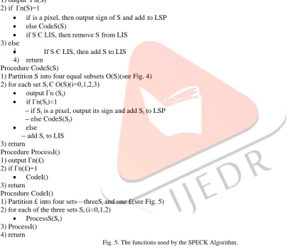
The main body of the SPECK coding algorithm is presented in pseudo-code in Fig. 4. It consists of four steps: the initialization step; the sorting pass; the refinement pass; and the quantization step. These steps call four functions,processS(), CodeS(), ProcessI() and CodeI(), which are described in Fig.5.
Procedure ProcessS (S_)
1) output Гn(S) 2) if Гn(S)=1
if _ is a pixel, then output sign of S and add _ to LSP else CodeS(S)
if S Є LIS, then remove S from LIS 3) else
If S Є LIS, then add S to LIS 4) return
Procedure CodeS(S)
1) Partition S into four equal subsets O(S)(see Fig. 4) 2) for each set Si Є O(S)(i=0,1,2,3)
output Гn (Si)
if Гn(Si)=1
– if Si is a pixel, output its sign and add Si to LSP
– else CodeS(Si)
else
– add Si to LIS 3) return
Procedure ProcessI() 1) output Гn(£) 2) if Гn(£)=1
CodeI() 3) return
Procedure CodeI()
1) Partition £ into four sets—threeSi and one £(see Fig. 5) 2) for each of the three sets Si (i=0,1,2)
ProcessS(Si_)
3) ProcessI() 4) return
Fig. 5. The functions used by the SPECK Algorithm.
IJEDR1401166
International Journal of Engineering Development and Research (www.ijedr.org)926
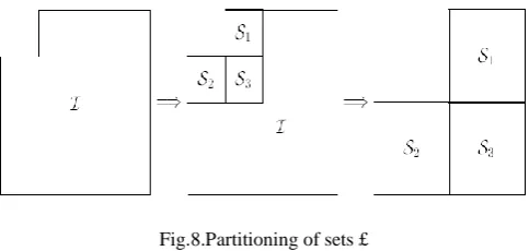
Fig.8.Partitioning of sets £
We shall now describe the operations of the SPECK algorithm presented in Fig. 1. We start with our source, a rectangular image X, that has undergone an appropriate sub band transformation. The image X consists of transformed coefficients {Ci,j}, located at pixel position (i,j) Such an image exhibits a hierarchical pyramidal structure having sub bands at different levels of its decomposition. The topmost band is the root of the pyramid.
V. RESULT AND CONCLUSION
The images taken for the experiment are „Lena‟,„Barbara‟, „Peppers‟, „Cameraman‟, „Mandrill‟, „Rice‟of size (256 X 256). They are subjected to wavelet and Multiwavelet decomposition. The wavelet filters used in this experiment are
“Haar”, “la8”, “Db4”,”Bi9/7”[10] SPECK algorithm is said to be an efficient algorithm than SPIHT [7]. Many comparison tables for different images are provided below from which the above said statement is made true.Tables 1 and 2 indicate the comparison between SPIHT and SPECK algorithm at different levels of decomposition in case of scalar wavelets and Multiwavelet for “Cameraman” image. From tables 4 and 5, it is evident that SPECK algorithm gives a higher PSNR than SPIHT at a given CR in the case of both scalar wavelets and Multiwavelet
Table 1. Comparison between SPIHT and SPECK for PSNR (in dB) values for “Cameraman” image using scalar wavelets.
Level
Filter SPHIT SPECK
Rate
(bpp) 0.2 0.6 1 0.2 0.6 1
2
Haar 12.4 16.98 20.04 18.28 26.62 31.05 Db4 12.53 17.19 20.029 20.40 28.32 32.51 La8 12.6 17.2 20.73 20.72 28.60 32.58 Bi9 12.57 17.31 20.46 20.38 26.78 28.99
3
Haar 15.83 24.31 29.87 23.24 29.19 32.51 Db4 16.18 24.68 30.23 23.76 30.30 34.37 La8 16.17 24.96 30.28 24.04 30.21 33.85 Bi9 16.38 23.53 26.52 22.82 26.33 27.50
Table 2. Comparison between SPIHT and SPECK for PSNR (in dB) values for “Cameraman” image using multi-wavelets.
Level
Filter SPHIT SPECK
Rate
(bpp) 0.2 0.6 1 0.2 0.6 1
2
Ghm 14.52 24.4 29.13 20.14 26.89 31.07 Cl 15.96 24.8 29.75 23.39 28.90 31.62 Sa4 16.07 24.9 30.06 23.62 29.80 33.75 Cdb3 17.17 25.7 60.46 18.27 26.14 29.89
3
Ghm 22.67 28.4 31.91 23.72 29.23 32.92 Cl 22.93 29.1 32.96 23.82 28.16 30.22 Sa4 23.25 29.2 33.09 24.67 30.08 33.94 Cdb3 23.62 28.9 32.42 23.52 29.45 33.33
The SPECK algorithm has some important features which are low complexity, embeddedness, progressive coding, exploits clustering of energy to zoom into high energy areas within a region (block) to code them with minimum significance maps, better visual perception, Better PSNR than SPIHT. The SPHIT algorithm has some important features which are good image quality, high PSNR, especially for color images; it employs progressive image transmission produces a fully embedded coded file; fast coding/decoding (nearly symmetric).
REFERENCES
IJEDR1401166
International Journal of Engineering Development and Research (www.ijedr.org)927
[2] James S. Walker,” Wavelet-based Image Compression” Sub-chapter of CRC Press book: Transforms and Data CompressionGeoffrey M. Devis,member IEEE,”A Wavelet based analysis of fractal image compression” to appear in IEEE transcations on image processing,1997
[3] R.Sudhakar, Ms R Karthiga, S.Jayaraman, Image Compression using Coding of Wavelet CoefficientsNetworks, ICGST-GVIP Journal, Volume (5), Issue (6), June 2005.
[4] K Sayood, “Introduction to Data Compression” , Morgan Kaufm ann, San Fransisco, USA, 1996.
[5] Said A. and Pearlman W., “A New, Fast and Efficient Image Codec Based Set-Partitioning In Hierarchical Trees,” IEEE Transactions Circuits and Systems for Video Technology, vol. 6, no. 3, pp. 243-250, June 1
[6] William A. Pearlman, Asad Islam, Nithin Nagaraj, and Amir Said Efficient, Low-Complexity Image Coding with aSet-Partitioning Embedded Block Coder
[7] Sudhakar R. and Jayaraman S., “Image Compression Using Multiwavelets and Wavelet Difference Reduction Algorithm,” in Proceedings of the International Conference on Resource Utilization and Intelligent Systems, pp. 1-8, January 2006
[8] Islam A. and William A., “Efficient, Low-Complexity Image Coding with a Set-Partitioning Embedded Block Coder,” IEEE Transactions Circuits and Systems for Video Technology, vol.14, pp. 1219-1235, November 2004.
[9] K., “Embedded Image Compression Based on Wavelet Pixel Classification & Sorting,” IEEE Transactions on Image Processing, vol. 13, no. 8, pp. 1011-1017, August 2004.