ISSN (Print) : 2320 – 3765 ISSN (Online): 2278 – 8875
I
nternational
J
ournal of
A
dvanced
R
esearch in
E
lectrical,
E
lectronics and
I
nstrumentation
E
ngineering
(An ISO 3297: 2007 Certified Organization) Vol. 4, Issue 3, March 2015
Design and Implementation of Shunt Active
Power Filter Based Predictive Control
Algorithm
G.Nirmal
1, Antharasi Vineesha
2Assistant Professor, Dept. of EEE, Prathyusha Institute of Technology and Management, Tiruvallur , Tamilnadu, India1
PG Student [Power electronics and drives], Dept. of EEE, Prathyusha Institute of Technology and Management,
Tiruvallur, Tamilnadu, India 2
ABSTRACT: A simple control scheme for Hybrid Active Power Filter which is developed by connecting the passive LC filter with the active power filter for compensating the non-linear load. n a hybrid active power filter, the active part is used to filter out the higher order harmonics, while lower order harmonics are eliminated by passive filter tuned for
5th and 7th order harmonic frequencies. The hybrid active power filter which contains the compensation characteristics
of both resonant passive and active filter. The hybrid active power provides better performances in the high voltage non- linear load compensation. Renewable Energy with Buck-boost converter is used to balance the DC Link voltage. The compensation performance is demonstrated through simulation and experimental results.
KEY WORDS: Active power filter, buck-boost converter, four-leg VSI
I.INTRODUCTION
The widespread increase of non-linear loads nowadays, significant amounts of harmonic currents are being injected into power systems Harmonic currents flow through the power system impedance, causing voltage distortion at the harmonics at the harmonic currents’ frequencies. The distorted voltage waveform causes harmonic currents to be drawn by other loads connected at the point of common coupling (PCC).The existence of current and voltage harmonics in power systems increases losses in the lines, decreases the power factor and can cause timing errors in sensitive electronics equipment. The continuous demand in power network has caused the system to be heavily loaded leading to voltage instability. Under heavy loaded conditions there may be insufficient reactive power causing the voltages to drop. This drop may lead to drops in voltage at various buses. The result would be the occurrence of voltage collapse which leads to total block out of the whole system. The active power filter for non- linear load along with its control scheme and also implemented with a four-leg voltage source inverter using a predictive control scheme is presented. The active power filter is used to compensate the reactive power, reduce harmonics in the source current and also injects the active power from the renewable energy source into the grid through voltage source inverter. The active power filter provide better performances in the high voltage non-linear load compensation. Renewable energy with Buck-boost converter is used to balance the dc link voltage. The predictive controller use to improve the performance of the active power filter, especially during transient operating conditions, because it can quickly follow the current - reference signal while maintaining a constant dc voltage. The compensation performance of the proposed active power filter and associated control scheme under steady state and transient operating conditions is demonstrated.
The advantages of Predictive Control Algorithm are the predictive control algorithm is used to predict the future behavior of the variables to be controlled, The controller uses this information to select the optimum switching state that will be applied to the converter, The predictive control algorithm is easy to implement and to understand.
II. EXISTING SYSTEM
ISSN (Print) : 2320 – 3765 ISSN (Online): 2278 – 8875
I
nternational
J
ournal of
A
dvanced
R
esearch in
E
lectrical,
E
lectronics and
I
nstrumentation
E
ngineering
(An ISO 3297: 2007 Certified Organization) Vol. 4, Issue 3, March 2015
four leg VSI using predictive control algorithm. The active power filter is used to compensate the reactive power reduce harmonics in the source current and also injects the active power from the renewable energy source into the grid through VSI .The active power filter provide better performance in the high voltage non-linear load. The predictive control algorithm is used to improve the performance of the active power filter, especially during transient operating
conditions. So the active power filter is connected to the four leg VSI using predictive control algorithm. Power quality
is a term used to broadly encompass the entire scope of interaction among electrical suppliers, the environment, the widespread use of non-linear loads is leading to a variety of undesirable phenomena in the operation of power systems.
.
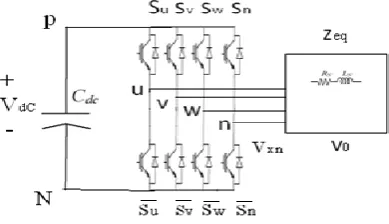
Fig. 1. Three-phase equivalent circuit of the proposed shunt active power filter
The harmonic components in current and voltage waveforms are the most important among these. Conventionally passive filters have been used to eliminate line current controlled voltage source inverters can be utilized with appropriate control strategy to perform active filter functionality. However, the extensive use of power electronics based equipment and non-linear loads at PCC generate harmonic currents, which may deteriorate the quality power. Recently various control strategies for grid connected inverters incorporate.
III.TWO-LEVEL FOUR-LEG PWM-VSI TOPOLOGY:
The voltage in any leg x of the converter, measured from the neutral point (n), can be expressed in terms of switching states, as follows:
Vxn= Sx− Sn Vdc, x= u, v, w, n. (1) The mathematical model of the filter derived from the equivalent circuit
Vo = Vxn – Reqio – Leq d io /dt (2)
Where Req and Leq are the 4L-VSI output parameters expressed as Thevenins impedances at the converter output
terminals Zeq .
Fig. 2 : Two-level four-leg PWM-VSI topology
Therefore, the Thevenins equivalent impedance is determined by a series connection of the ripple filter impedance Zf
and a parallel arrangement between the system equivalent impedance Zs and the load impedance ZL
ISSN (Print) : 2320 – 3765 ISSN (Online): 2278 – 8875
I
nternational
J
ournal of
A
dvanced
R
esearch in
E
lectrical,
E
lectronics and
I
nstrumentation
E
ngineering
(An ISO 3297: 2007 Certified Organization) Vol. 4, Issue 3, March 2015
For this model, it is assumed that ZL _ Zs, that the resistivepart of the system’s equivalent impedance is neglected,
andthat the series reactance is in the range of 3–7% p.u., which isan acceptable approximation of the real system.
Req = Rf and Leq = Ls+ Lf .
Fig 2 shows the basic compensation principle of the shunt APF. A shunt APF is designed to be connected in parallel with the load, to detect its harmonic current and to inject into the system a compensating current, identical with the load harmonic current. Therefore, the current draw from the power system at the coupling point of the filter will result sinusoidal as shown in Fig. 2and Eq. (1) fig2shows load current (iL), compensating current reference (iC) and desired sinusoidal source current (iS) waveform, respectively.
iS= iL+ Ic
In 3-phase 4-wire systems, two kinds of VSI topologies such as 4-leg inverter and 3-leg (split capacitor) inverter are used. The 4-leg inverter uses 1-leg specially to compensate zero sequence (neutral) current. The 3-leg inverter is preferred for due to its lower number of switching devices, while the construction of control circuit is complex, huge DC-link capacitors are needed and balancing the voltage of two capacitors is a key problem. The 4-leg inverter has advantage to compensation for neutral current by providing 4th-leg and to need for much less DC-link capacitance and has full utilization of DC-link voltage. The 4-leg VSI has 8 IGBT switches and an energy storage capacitor on hysteresis–band current controllers is used to obtain the VSI control pulses for each inverter branch. High order harmonic currents generated by the switching of the power.
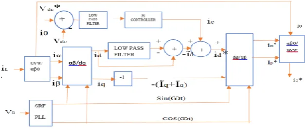
Fig. 3 : dq-based current reference generator block diagram.
The predictive control algorithm is used to predict the future behavior of the variables to be controlled. The dq-based scheme operates in a rotating reference frame; therefore, the measured currents must be multiplied by the sin(wt) and cos(wt) signals. By using dq-transformation, the d current component is synchronized with the corresponding
phase-to-neutral system voltage, and the q current component is phase-shifted by 90◦.The sin(wt) and cos(wt) synchronized
reference signals are obtained from a synchronous reference frame (SRF) PLL [29]. The SRF-PLL generates a pure sinusoidal waveform even when the system voltage is severely distorted. Tracking errors are eliminated, since SRF-PLLs are designed to avoid phase voltage unbalancing, harmonics (i.e., less than 5% and 3% in fifth and seventh, respectively), and offset caused by the nonlinear load conditions and measurement errors [30].A low-pass filter (LFP)
extracts the dc component of the phase currents id to generate the harmonic reference components −𝑖𝑑~.The reactive
reference components of the phase-currents are obtained by phase-shifting the corresponding ac and dc components of
𝑖𝑞by 180◦.In order to keep the dc-voltage constant, the amplitude of the converter reference current must be modified
by adding an active power reference signal𝑖𝑒with the d-component, as will be explained in Section IV-A. The resulting
signals𝑖𝑑∗and 𝑖𝑞∗are transformed back to a three-phasesystem. Low pass filters are used to remove or attenuate the higher
ISSN (Print) : 2320 – 3765 ISSN (Online): 2278 – 8875
I
nternational
J
ournal of
A
dvanced
R
esearch in
E
lectrical,
E
lectronics and
I
nstrumentation
E
ngineering
(An ISO 3297: 2007 Certified Organization) Vol. 4, Issue 3, March 2015
the controller error, e(t). The combination of proportional and integral terms is important to increase the speed of the response and also to eliminate the steady state error. The PID controller block is reduced to P and I blocks.
IV. PROPOSED SYSTEM
Renewable energy with buck-boost converter is used to balance the dc link voltage. The active power filter is used to compensate the reactive power, reduce harmonics in the source current and also injects the active power from the renewable energy source into the grid through VSI.
Fig. 4: Three-phase equivalent circuit of the proposed shunt active power filter
The active power filter provide better performances in the high voltage non -linear load. The predictive control algorithm is used to improve the performance of the active power filter, especially during transient operating conditions. At present in India 70% of the source for generation of power is coal. Conventional process includes inversion, step up, transmission, step-down, rectification and filtration for the utilization of power. At the utility end many DC appliances work on different voltage levels. Buck boost converter provides the voltage levels by stepping up/ down the available input as per the requirement. The VSI, or variable source inverter, was the earliest solid state adjustable frequency AC drive. It is sometimes called a "six-step" drive because of the voltage sent to the motor. VSI operation is relatively simple. AC input voltage and frequency is converted to DC by rectifiers, then converted back to AC through the inverter section, which produces the desired voltage and frequency to meet the volts per hertz ratio at the drive output. The advantages of VSIs include Good Speed Range, Multiple motor control from a single unit, and simple regulator design. Some disadvantages include decreasing power factor with decreasing speed, induced harmonics, "cogging", jerky start/stop motions.
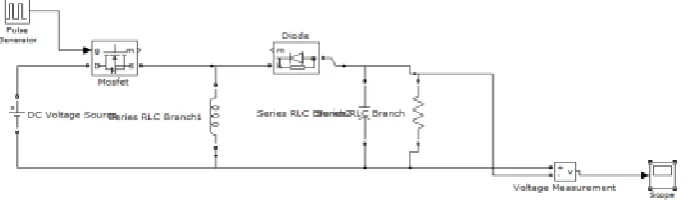
A.Buck-Boost Converter: Buck-Boost is the one in which the buck as well as boost operation is possible i.e. the input voltage can be varied from minimum value to a maximum value.
Fig. 5: Buck-boost converter
ISSN (Print) : 2320 – 3765 ISSN (Online): 2278 – 8875
I
nternational
J
ournal of
A
dvanced
R
esearch in
E
lectrical,
E
lectronics and
I
nstrumentation
E
ngineering
(An ISO 3297: 2007 Certified Organization) Vol. 4, Issue 3, March 2015
Fig 6 : output voltage of buck-boost converter
The output voltage from the buck boost converter is 24v.
V. SIMULATION AND ITS RESULTS
Fig.7 : Three phase source voltage of open loop.
Fig. 8 : Three phase load voltage of open loop.
The input voltage from the open loop is 210v
ISSN (Print) : 2320 – 3765 ISSN (Online): 2278 – 8875
I
nternational
J
ournal of
A
dvanced
R
esearch in
E
lectrical,
E
lectronics and
I
nstrumentation
E
ngineering
(An ISO 3297: 2007 Certified Organization) Vol. 4, Issue 3, March 2015
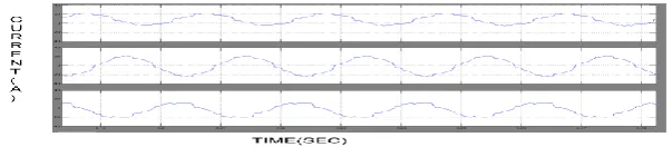
The value of the three phase load current is 20A
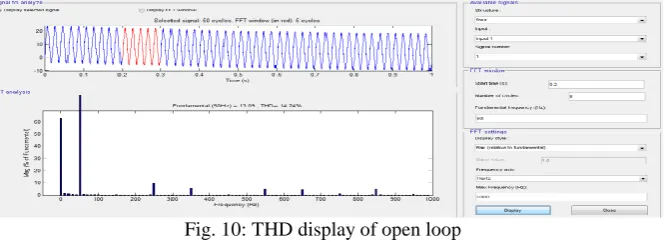
Fig. 10: THD display of open loop
Fig10 shows the total harmonic distortion display at the output side for an uncompensated model. The load voltage and current is taken as the input. It displays the four continuous cycles of load voltage in which the distortions obtained is
as 14.24% at the fundamental frequency.
Fig. 11: Three phase source voltage of closed loop.
The above figure represents the input voltage of the compensated system and the source voltage is between time(sec) and voltage(v).
Fig. 12 : Three phase load voltage of closed loop.
ISSN (Print) : 2320 – 3765 ISSN (Online): 2278 – 8875
I
nternational
J
ournal of
A
dvanced
R
esearch in
E
lectrical,
E
lectronics and
I
nstrumentation
E
ngineering
(An ISO 3297: 2007 Certified Organization) Vol. 4, Issue 3, March 2015
Fig. 13: Three phase output current of closed loop
The output current is 24v from the compensated system.
In uncompensated system the THD (Total harmonic distortion) is 14.2 percent. From compensated system by using the predictive control algorithm the THD is 5.07 percent
Fig. 14: Total harmonic distortion display at the output side for a compensated model
The load voltage and current is taken as the input. It displays the three continuous cycles of load voltage in which the distortions obtained is as 5.07%at the fundamental frequency.
VI.CONCLUSION
This project describes a predictive control algorithm used as reactive power compensation and voltage regulation for VSC-based shunt active power filter. The proposed Predictive controller consists of the inner current loop and outer voltage loop controller. For the inner loop, the predictive control algorithm is employed to generate proper switching functions for the VSC-Based shunt active power filter and to achieve the current and voltage regulation. The simulation results shows that the proposed model can compensate the reactive power flow thereby improving the system response and improving the power factor. Therefore, the proposed predictive control strategy is adequate for VSC-based shunt active power filter. Simulated and experimental results have shown the compensation effectiveness of the proposed active power filter.
REFERENCES
[1]. Ahmed Faheem zobaa, senior member ,SSSSIEEE ―Optimal Multi objective Design of Hybrid Active Power Filters Considering a Distorted Environment‖
[2]. Ricardo Lucio de Araujo Ribeiro, Member , IEEE ,Christian Cesar de Azevedo ,and Raphaell macieldesousa―A Robust Adaptive Control Strategy of Active Power Filters for Power-Factor Correction, Harmonic Compensation and Balancing of Non- Linear Loads‖
ISSN (Print) : 2320 – 3765 ISSN (Online): 2278 – 8875
I
nternational
J
ournal of
A
dvanced
R
esearch in
E
lectrical,
E
lectronics and
I
nstrumentation
E
ngineering
(An ISO 3297: 2007 Certified Organization) Vol. 4, Issue 3, March 2015
[4]. 1.shweta RMalluramath 2.Prof V.M. Chougala Department of ECE,Vishwanathrao Deshpande Rural Institute of Technology,Haliyalvisvesvaraya Technical University, Belgaum, Karnataka, India. ―Improving the power quality by four leg VSI‖
[5].Control of a 3-phase 4-leg active power filter under non-ideal mains voltage condition
Mehmet Ucar,EnginOzdemlirKocaeli University, Technical Education Faculty,Electrical Education Department, 41380 Umuttepe, Turkey
[6]. Lalithadarbha, shrivatsav. P. Madabal sneha. B. Karkishradha. B. Mattikattividya. V. Hiremath, s.g.balekundri institute of technology, belgaum―Efficient utilization of Renewable Energy For Multiple Utilities by Buck-boost converter‖
[7]. Maja Harfman Todorovic, Leonardo Palma ,Prasad Enjeti ―Design of a Wide Input Range DC-DC Converter with a Robust Power Control Scheme Suitable for Fuel Cell Power Conversion‖
[8]. Hisham Mahmood, Dennis Michaelson, and Jin Jiang ―Control Strategy for a Standalone PV/Battery Hybrid System
[9].A.Majid, J.Saleem, H.B.Kotte, R.Ambatipudi, K.Bertilsson ―Design and implementation of EMI filter for high frequency (MHz) power converters‖
[10].K. K. Tse, Henry Shu-hung Chung, Member, IEEE, S. Y. R. Hui, Senior Member, IEEE, and H. C. So, Member, IEEE ―A Comparative Investigation on the Use of Random Modulation Schemes for DC/DC Converters‖
[11] S. Ali, M. Kazmierkowski, ―PWM voltage and current control of four-legVSI,‖ presented at the ISIE,Pretoria, South Africa, vol. 1, pp. 196– 201,Jul. 1998
[12]. S. Kouro, P. Cortes, R. Vargas, U. Ammann, and J. Rodriguez, ―Modelpredictive control—A simple and powerful method to control power converters,‖IEEE Trans. Ind. Electron., vol. 56, no. 6, pp. 1826–1838, Jun.2009
[13]. D. Quevedo, R. Aguilera, M. Perez, P. Cortes, and R. Lizana, ―Modelpredictive control of an AFE rectifier with dynamic references,‖ IEEE Trans. Power Electron., vol. 27, no. 7, pp. 3128–3136, Jul. 2012.
[14] Z. Shen, X. Chang, W. Wang, X. Tan, N. Yan, and H. Min, ―Predictivedigital current control of single-inductor multiple-output converters in CCM with low cross regulation,‖ IEEE Trans. Power Electron., vol. 27,no. 4, pp. 1917–1925, Apr. 2012
[15].M. Rivera, C. Rojas, J. Rodriidguez, P. Wheeler, B. Wu, and J. Espinoza,―Predictive current control with input filter resonance mitigation for adirect matrix converter,‖ IEEE Trans. Power Electron., vol. 26, no. 10,pp. 2794–2803, Oct. 2011.
[16].M. Preindl and S. Bolognani, ―Model predictive direct speed control withfinite control set of PMSM drive systems,‖ IEEE Trans. Power Electron.,2012.
[17].T. Geyer, ―Computationally efficient model predictive direct torque control,‖IEEE Trans. Power Electron., vol. 26, no. 10, pp. 2804–2816, Oct.2011.
[18].M. I. M. Montero, E. R. Cadaval, and F. B. Gonzalez, ―Comparison ofcontrol strategies for shunt active power filters in three-phase four-wiresystems,‖ IEEE Trans. Power Electron., vol. 22, no. 1, pp. 229–236, Jan.2007.