Numerical simulation of stress-strain state of
oblique
sections
of
reinforced
concrete
structures subjected to compression and
bending on yielding supports under short-term
dynamic load
Nikita Mescheulov1,*, and Oleg Kumpyak1
1Tomsk State University of Architecture and Building, Tomsk 634003 Russia
Abstract. This research is aimed at studying the method for improving blast resistance of buildings and structures by using yielding supports. The paper reports the data on dynamic analysis of reinforced concrete elements subjected to compression and bending on yielding supports under the condition of elasto-plastic stress-strain state performed in ANSYS software package. Algorithms and techniques for dynamic amplification factor calculation for reinforced concrete elements subjected to compression and bending are presented. The paper provides load diagrams of dynamic amplification factors with the account of yielding capacity of supports for subsequent dynamic analysis of structures for equivalent static load.
Introduction
Due to rapidly growing possibility of natural or man-made dynamic actions occurrence in buildings and structures, the necessity to design reinforced concrete structures resistant to such actions is becoming ever more frequent. Special attention is paid to the risk of shock waves caused by explosions of conventional explosives during their storage, transportation, or as a result of terrorist attacks, etc.
Because of short period of action and high intensity loads that occur in such cases often result not only in local damage or complete failure of a structure, but also cause loses of technological equipment, injuries and casualties. For that reason solution to the issue of blast resistant buildings and structures has an important economic and social meaning.
Presently, two essentially different types of solution are used to ensure accommodation of dynamic loads by buildings and structures.
The first type provides increase of bearing capacity of the structures by using materials with improved physico-mechanical characteristics (high-performance concrete and rebars, composite rebars, fiber concrete), more intense reinforcement, increase of cross-section of elements. At the same time, structures performance in regions of massive plastic deformations is acceptable.
Bended elements and structures under compression and bending are the main ones when analyzing buildings and structures for highly intense dynamic actions. Such structures include floor slabs, cross beams, columns. Occurrence of high plastic deformations may result in local or complete failure of a building. Besides, enhancing dynamic strength by improving geometrical and strength parameters of structures is not always technologically possible or economically feasible.
An alternative protection option is decrease of intensity and containment of dynamic action by using both blast relief elements (floor slabs and envelope structures) and brittle elements and devices. In the first case, the building design provides failure of support fixing of some elements under the action of shock waves, which causes detachment of load bearing structures and release of shock waves through such openings. In the second case, it is suggested to install in buildings some structures or devices (yielding supports [1-8]) which when deforming will take up excessive blast energy, thus unloading and protecting bearing elements from damage and failure.
Today, the research outcomes in the field of using yielding supports for protection of structures damaged by extremely intense dynamic loads are only partially presented. The reported experimental and theoretical studies [9-13] demonstrate both positive and negative impact of yielding capacity of support fixing on dynamic response of reinforced concrete (RC) bended structures.
Hence, the research aimed at studying RC structures subjected to bending and compression with yielding support fixing under short-term dynamic loading is relevant and has important meaning while designing economically effective and reliable buildings and structures.
1 Calculation method
Simulation of dynamic deformation of oblique sections of RC bended structures and elements subjected to bending and compression on rigid and yielding supports was carried out using Ansys Explicit Dynamics software, version 17.2.
Under study is a beam subjected to compression and bending in conventional elastic stage corresponding to limit state 1а [14]. The level of longitudinal compression is varied, as well as two stages of supports deformation: conventional non-deformable (rigid) stage and elasto-plastic stage [10].
The calculation is performed for a RC beam structure subjected to bending and compression with the section parameters of h=40 cm, b=20 cm, and with the span of l=4 m. In normal sections the beam is reinforced with hot-rolled А400 (µs=2%) rebars. In oblique
sections the beam is reinforced with hot-rolled А240 rebars. Bilinear dependence of plastic deformation of steel with isotropic hardening was used in the calculation as a law of longitudinal and transverse reinforcement deformation. Concrete of B20 class was used and described with Riedel-Hiermaier-Thoma (RHT) model of combined plasticity and failure. The beam is designed with equal strength for normal and oblique sections.
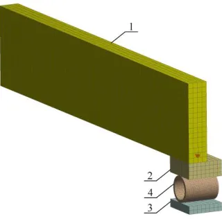
Fig. 1. General view of the FE model: 1 – reinforced concrete sample; 2 – moveable support plate; 3 – immoveable loading support plate; 4 – yielding support
For this reason the rest three quarters of the model were replaced by horizontal perpendicular symmetry planes (Fig. 2) describing the reverse behavior of the sample parts.
a) b)
Fig. 2. Symmetry planes (in red): a – transverse; b – longitudinal
In cases of calculation of structures subjected to bending and compression the first stage provided application and retention of longitudinal force (Fig. 3a) which is applied as evenly distributed load along the entire side surface of the beam and equals (0; 0.2; 0.4) Rbn, where
Rbn is characteristic compressive strength of concrete (MPa).
After that, simulation of transverse dynamic action (Fig. 3b) was performed with regard to immediately increased load with linear descent (Fig. 4).
This linear manner of dynamic load variation in time is applied for calculation of roof structures, side and front load bearing structures in buildings during external explosion of condensed explosives [15].
Fig. 4. Immediate increase of dynamic load with linear descent
When calculating the linearized law of pressure variation in time was applied which is defined by the dependence (1).
The shock wave effective time (θ) was set depending on multiple parameters: distance from the charge center, mass of the charge, distance between the charge and the affected building. In calculation of serviceability limit state only conventional elastic stage of structural deformation (limit state 1а) is provided. In RC structures with longitudinal reinforcement deformations of tensed rebars stay within elastic deformation stage, however in tension zones crack formation is possible. Following the recommendations in [15], the time of elastic stage end te2 when calculating according to the limit state 1а is defined by
dependences (2) and (3)(3).
where,
First mode natural frequencies ω1 are calculated on the basis of the set geometrical and
physical parameters. After that, the parameter θ is defined from the dependences (2) and (3) for a certain calculation case.
The maximum value of dynamic load (ΔPmax) is determined with the method of
successive approximations by using iterative structural analysis with controlling occurrence of limit states 1а or1b based on deformation criterion.
In calculation referring to load bearing capacity (or plastic deformation limitation) the state 1b is the time of the end of elastic stage t
e1, we accept te1=0.5 te2. Natural frequency of
a simply supported beam without longitudinal compression is determined from the dependence (6)
∆𝑃(𝑡)= ∆𝑃𝑚𝑎𝑥(1 − 𝑡
𝜃) , 0 ≤ 𝑡 ≤ 𝜃 (1)
𝑡𝑒2= (
2𝑎𝑟𝑐𝑡𝑔𝜔1𝜃
𝜔 ) , 𝑤𝑖𝑡ℎ 𝜔1𝜃 ≥ 2.33 (2)
𝑡𝑔𝜔1(𝑡𝑒2− 𝜃) = 𝐴
𝐵, 𝑤𝑖𝑡ℎ 𝜔1𝜃 < 2.33 (3)
𝐴 = − 1 𝜔1𝜃
+ 𝑠𝑖𝑛 𝜔1𝜃 +
𝑐𝑜𝑠 𝜔1𝜃 𝜔1𝜃
(4)
𝐵 = − 𝑐𝑜𝑠 𝜔1𝜃 +
𝑠𝑖𝑛 𝜔1𝜃 𝜔1𝜃
(5)
𝜔1= 𝜋2
𝑙2 √ 𝐵
where m – mass per unit length expressed in t/m, В – bending stiffness of RC elements with rectangular section with a single rebar and cracks in tension zone of concrete, expressed in kN/m2. This parameter is defined for standard static material resistance with the account of
cracks in concrete of tension zone and is found from the formula (7) .
where Es – rebar elastic modulus, As – area of cross-section of tensed rebar; h0 – effective
depth of section, x – height of compression zone of concrete.
After finding ΔPmax dynamic amplification factor kd = Pυ /ΔPmax is set for certain values
of ω1θ.
2 Results
2.1 Beam structures with longitudinal compression on rigid supports
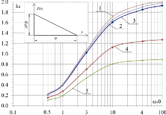
The diagram (Fig. 5) illustrates the obtained results for calculating dependence of dynamic amplification factor for beams with and without longitudinal compression in conventional elastic stage. The data are given for a certain limit state 1а and rigid support depending on the product of first mode natural frequencies (ω1) and time of dynamic load application (θ).
Good convergence was found between the research outcomes of this study and other previously reported results (Fig. 5) on the use of dynamic amplification factor kd for
structures on rigid supports [14, 15] and elastic supports with higher stiffness [13]. The difference is between 0 % and 6 % depending on ω1θ parameter.
Reduction of dynamic amplification factor of the load kd is observed for different levels
of longitudinal compression (Fig. 5, 4; 5). For instance, the average reduction for beams subjected to longitudinal compression N = 0,2Nmax compared to beams without compression
is 1.52 times.
Fig. 5. Diagram for dynamic amplification factor for beams in conventional elastic stage (limit state 1а) on rigid supports depending on the level of longitudinal compression and ω1θ parameter; 1 – B.S. Rastorguev, A.I. Plotnikov, D.Z. Khusnutdinov [15] (no longitudinal compression); 2 – A.S. Abdul-Rakhman [13] (no longitudinal compression); 3, 4, 5 – the authors’ research outcomes, 3 – beams without compression, 4 – structures subjected to longitudinal compression N = 0,2Nmax, 5 – beams
When increasing compression up to N = 0,4Nmax reduction of kd in comparison with
beams under compression N = 0,2Nmax is 1.4 times, whereas compared to beams without
compression kd parameter reduces by 2 to 2.2 times.
It should be noted that increase of longitudinal compression leads to reduction of dynamic amplification factor irrespective of ω1θ parameter. For instance, for ω1θ = 0.5
reduction of kd factor for beams subjected to compression N = 0,4Nmax is 2.09 times
compared to that for beams with no compression; and for ω1θ = 100 the factor reduction is
2.17 times. At the same time, increase of dynamic amplification factor kd was observed
along with growth of ω1θ parameter. Thus, for a structure with no compression and ω1θ =
0.5 the value of dynamic amplification factor kd is 0.23, whereas for ω1= 100 is equals
1.93. For beam structures subjected to bending without compression the value of kd
decreases by 8.8 times, for beams subjected to compression N = 0,2Nmax – by 8.5 times, and
for structures subjected to compression N = 0,4Nmax – by 8.1 times.
2.2 Beam structures on yielding supports under various level of compression
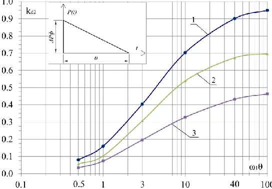
The dynamic factor diagram (Fig. 6) demonstrates dependences of kd2 factors for beams on
supports in elasto-plastic stage.
When increasing compression up to N = 0,4Nmax the kd2 factor reduces by 1.5 to 2 times
compared to the case of the beams subjected to compression N = 0,2Nmax. With reference to
beams with no compression the kd2 factor reduces by 2.6 to 2 times as ω1θ parameter
increases.
The analysis of performance of beams on yielding supports in comparison with that on rigid supports with the account of longitudinal compression showed that the least desired combination is deformation of structures on rigid supports without longitudinal compression (Fig. 5, 1-3).
Under these conditions the values of dynamic amplification factor kd varies between
0.22 and 1.93 depending on ω1θ parameter. The higher ω1θ value is, the higher kd factoris.
Performance of beams subjected to longitudinal compression N = 0,4Nmax on yielding
supports deformed in elasto-plastic stage is found to be the most effective (Fig. 6, 3). For such combination kd2 value belongs to the range between 0.03 and 0.46.
Notably, similar to the case of rigid supports the increase of kd2 factor occurs along with
the increase of ω1θ value. Reduction of kd2 factor value varies between 6.3 and 4.2 times.
The best result corresponds to the lowest value of ω1θ. And with increase of this parameter
the mentioned effect decreases. Thus, with ω1θ = 0.5 for a beam with no compression on
rigid supports the factor kd = 0.21, and for a beam on yielding supports under compression
N = 0,4Nmax the factor kd2= 0.03. This means that the factor reduced by 6.3 times. With ω1θ
= 10, for a beam without compression on rigid supports the value of kd factor is 1.61,
whereas for structures on yielding supports under compression N = 0,4Nmax it is 0.33. The
factor reduction in this case is 4.9 times. With ω1θ = 10, taking a beam with no
compression on rigid supports the factor kd value is 1.93, and for a beam on yielding
supports and subjected to compression N = 0,4Nmax the kd2 value is 0.46. Hence, the factor
reduction is 4.2 times.
Comparative analysis of dynamic resistance of RC structures demonstrates that longitudinal compression and yielding supports have significant effect on bearing capacity of the element. Notably, supports that perform in plastic stage prove to be the most effective.
Conclusion
1. Forces occurring in longitudinal rebars and corresponding to the limit state 1a are characterized by dynamic amplification factors kd,kd2.The obtained factors are presentedin
the form of diagrams, which significantly simplifies analysis of reinforced concrete beam structures for equivalent static loads.
2. Dynamic amplification factors kd, kd2 depend on the following parameters: relation of
yielding support stiffness and structure stiffness (W), product of first mode natural frequencies (ω1) and time of dynamic load application (θ), and the level of longitudinal
compression.
3. Reduction of dynamic amplification factors is observed for structures deformed in conventional elastic stage with the increase of longitudinal compression up to N = 0,4Nmax.
In case of rigid supports such reduction is up to 2 times, and for yielding supports – up to 2.6 times.
4. Relation of yielding support stiffness and structure stiffness is an essential parameter for dynamic amplification factors kd2. Decrease of its value for yielding support causes
reduction of kd2 up to 90%.
5. Performance of a beam subjected to longitudinal compression N = 0,4Nmax on yielding
supports in plastic stage proves to be the most effective. Thus, reduction of dynamic amplification factor kd2 for beams on yielding supports compared to the dynamic
amplification factor kd for rigid supports reaches between 4.2 and 6.3 times.
References
1. S. Poonaya, C. Thinvongpituk and U. Teeboonma, Proceedings of WASET, 26, 329 - 334 (2007)
2. P. Mata, A. Barbat, S. Oller and R. Boroschek, Arch. comput. methods eng, 15, 489 - 539 (2008)
3. G. Nagel, “Impact and energy absorption of straight and tapered rectangular tubes”, Ph.D. thesis, Queensland University of Technology (2005)
5. A. Ahmad Zaidi and G. Ling Lang, Journal of Science and Technology, 2, 563 - 580 (2011)
6. J. Marzbanrad, M. Mehdikhanlo and A. Saeedi Pour, Turkish J. Eng. Env., 33, 159 – 166 (2009)
7. Y. Zhao and J. Fang, International Journal of Pressure Vessels and Piping, 67, 257 - 261 (1996)
8. A. Ghaidan, Tikrit Journal of Eng. Sciences, 18 (3), 52-60 (2011)
9. O. Kumpyak, Z. Galyautdinov and D. Kokorin, II All-Russian Scientific Conference of Young Scientists “Advanced Materials in Technology and Construction”, 1698, (2015) (in Russian)
10. O. Kumpyak and N. Meshcheulov, Vestnik TSUAB, 6, 70-80 (2014) (in Russian) 11. A. Kezmane, B. Chiaia, O. Kumpyak, V. Maksimov and L. Placidi, European Journal
of Environmental and Civil Engineering, 20, 1-38 (2016)
12. B. Rastorguev, Building mechanics and analysis of structures, 1, 50-57 (2009) (in Russian)
13. A.S. Abdul-Rakhman, Increase of load-bearing capacity of concrete structures under impact loads, (PhD Thesis, Moscow, 1995) (in Russian)
14. SP 88.13330.2014 The protective shelters of civil defense, 122, (2013). (in Russian) 15. B.S. Rastorguev, A.I. Plotnikov, D.Z. Khusnutdinov, Proektirovanie zdaniy i