Radiation containment at a 1 MW high energy electron accelerator:
Status of LCLS-II radiation physics design
M. Santana Leitner1,a, J. Blaha, M. W. Guetg, Z. Li, J. C. Liu, S. X. Mao, L. Nicolas, S. H. Rokni, S. Xiao, and L. Ge
1SLAC National Accelerator Laboratory, 2575 Sand Hill Road, 94085-CA, USA
Abstract. LCLS-II will add a 4 GeV, 1 MHz, SCRF electron accelerator in the first 700 meters of the SLAC 2-mile Linac, as well as adjustable gap polarized undulators in the down-beam electron lines, to produce tunable, fully coherent X-rays in programmable bunch patterns. This facility will work in unison with the existing Linac Coherent Light Source, which uses the legacy copper cavities in the last third of the linac to deliver electrons between 2 and 17 GeV to an undulator line. The upgrade plan includes new beam lines, five stages of state of the art collimation that shall clean the high-power beam well up-beam of the radio-sensitive undulators, and new electron and photon beam dumps. This paper describes the challenges encountered to define efficient measures to protect machine, personnel, public and the environment from the potentially destructive power of the beam, while maximizing the reuse of existing components and infrastructure, and allowing for complex operational modes.
1 Introduction
LCLS-II will bring high-power electron operations back to SLAC. Such endeavor entails a broad span of challenges, some of which are presented here. The addition of su-perconducting cryomodules means potential generation of field-emission dark current, the mitigation of which needs to be designed by using developing and applying new models. Also LCLS-II is expected to have higher beam losses than its predecessor LCLS, and those will need to be cleaned to ensure its undulators are not damaged by ra-diation, which means that dark current will be strategically shredded in other areas, where shielding will be required. Not only will normal losses be higher, but also accidents can be more severe, and thus, shut-offmechanisms ought to be fast, and containment has to be designed to capture any high-power errant beams. Finally, the machine will use existing buildings, many of which were designed for low power beams, and which typically cannot be retro-fitted, or have no room for additional local shielding.
2 Beam Losses
2.1 Field emission from superconducting cavities
The high-power of LCLS-II electron beam will be sup-plied at 35 cryomodules distributed in four cold sections, and separated by bunching chicanes with halo cleaning collimators. Each cryomodule has eight nine-celled nio-bium cavities followed by a quadrupole, all cooled with liquid helium at∼2 K. The first cryomodule will operate at a high frequency of 3.9 GHz, while all others will run
ae-mail: [email protected]
at 1.3 GHz. The nominal acceleration at cryomodules is set at 16 MV/m, although higher gradients may be used if cavities are not found to emit substantial dark current.
Because the aperture through the cold sections is large (70 mm), normal beam losses are not expected there. However electrons field-emitted in high gradient RF ar-eas of the cavities will hit the iris of the cavities and other components, sometimes after having captured sufficient energy to the generate subsequent showers, thereby poten-tially damaging superconducting components, insulators, etc. Such effects were extensively studied [1] by recur-sively transferring field-emission and EM transport data and the generated radiation transport cascades between Track3P [2] and FLUKA [3, 4] on a 3D model with up to nine fully detailed back-to-back cryomodules, fig. 1.
It was found out that for nominal 10 nA/cryomodule ’captured’ field emission, i.e. dark current generated in a cryomodule and escaping at each of its ends, prompt dose rates at the upper Klystron Gallery1 were insignifi-cant, while residual dose rates during access to the linac aisle after one hour cool-down would be just under the 50μSv/h goal, meaning that the Linac aisle is not expected to fall into theRadiation Areaclassification.
As formachine protection, results of energy deposition at the niobium cavities indicate that heat generation from field-emitted electrons hitting the cavities will be negli-gible towards RF heating, and also that fundamental al-terations to the crystalline structure of Nb should not be expected, as peak dose levels are far below any of the es-tablished damage thresholds for metals. Regarding
Figure 1.Flair [5] rendering of the FLUKA model for nine full cryomodules. Outer total fluence (un-normalized) from field-emission is overlaid in the vertical plane. The dose pattern on a cavity is shown in the lower right corner.
vival of cables, of insulators and of electronic components which could be installed in several positions within the cryomodules or outside in the Linac, a new function for
FLUKA (SIDO) was developed [6] to computeabsorbed
dose fields, i.e. maps that display what the absorbed dose would be in each voxel should a light material be placed any of those positions. That function, which is folded real-time with the fluence histogram in a similar fashion as how biological dose is computed via run-time effective dose conversions, can be set for millimetric polyethylene type objects such as cables and insulators or for sub-millimetric silicon, representing electronics.
The resulting absorbed dose maps indicated that cer-tain light materials (less robust to radiation) shall be
avoided near the cavities. Indeed dose rates may
ex-ceed 100 kGy/y in some locations inside the cryomodules, while the level drops below 30 kGy/y under the cryomod-ules and to 0.2 kGy/y above those due to the attenuation provided by the large central Helium pipe above the cavi-ties.
Two findings were made for the superconducting quadrupoles. First, its coils are expected to last for more than 20 years of operation. Second, their magnetic rigid-ity was found to play a major role in the distribution and intensity of field emission losses. At medium
en-ergies (∼700 MeV), dose rates in the cryomodules from
field emission induced showers are highest, while maximal transmission of field-emitted electrons to warm sections occurs for switched offquads, reaching integrated intensi-ties of 25 W/nA for a string of 20 cryomodules. Such dark current beam resulting from accidentally powering offall cryomodule quadrupoles, would be cleaned up in the colli-mation sections, which also remove other undesired terms, as described next.
2.2 Additional beam loss terms: collimation shielding
LCLS-II halo collimation base-line design includes a first energy collimator followed by four transverse collimators
(in bunch compressors), a second energy collimator in the dogleg, more transverse collimators in the by-pass line and both energy and transverse collimators in the transfer lines to the undulators. LCLS-II collimators do not have a line of sight with down-beam undulators, thereby reducing ir-radiation of those by secondaries.
Energy collimators are especially effective in the up-stream end of the machine due to the large energy spread of the gun dark current, while down-beam collimators mainly serve to suppress gas-scattered electrons in the by-pass line. ASTRA [7] was used to simulate the gun dark current up to the first cryomodule, and ELEGANT [8] from there on [9]. No dark current from either the cathode or cavity field emissions has been found to lead to appre-ciable losses at the undulator, according to Top-up track-ing. Intra-beam scattering losses is below half a milliwatt in the undulator for the worst conditions (300 pC/120 kW). Currently, higher order field errors are being studied, sug-gesting only small corrections.
With respect to LCLS, the effective collimator thick-ness has been increased to 15 radiation lengths by select-ing Tungsten, rather than Titanium as material, based on Monte Carlo simulations of the collimator inefficiency.
Once the locations, sizes, materials and beam losses at the collimators had been established it was time to evalu-ate what would be the required shielding around every col-limator. The concerns that needed to be addressed were the residual dose rate near those at Linac access times (one hour cool-down), and the radio-activation of soil and groundwater surrounding the Linac. The first criteria dic-tates the shielding between the collimator and the most accessed areas (i.e. aisle side, and above or below the col-limator if the beam-line is low or high, respectively), while the second rules the shielding between the collimator and the closest/thinnest walls. A summary of these aspects, is presented below.
Simulations for the various energy/power
combina-tions with local shielding of several thicknesses were per-formed to find the shielding requirements in terms oflocal
activation. Results showed that at 98 MeV, beam losses
of 32 W would need to be shielded by a 8-cm thickcast
ironplate, while this thickness could be reduced to 6 cm by usinglead plates. Also it was observed that, regard-less of beam energy, below 20 W losses, shielding is not generally required. However, most collimators should be equipped with thin wire meshes or plastic barriers at 40 cm from the jaws to keep personnel away from the relatively high residual dose rates on the collimator surfaces, even for low loss rates. Also, it should be pointed out thatcast ironresidual dose shielding plates shouldnotbe replaced by some steel alloy, since some of the components of the latter could even render residual dose rates in the tunnel higher that they would be without any local shielding.
con-tain the leaking neutrons from each of the halo collimators of LCLS-II.
First, theproduction rateof various radio-isotopes was simulated in FLUKA for a broad array of configurations, including several target materials, beam energies, and lo-cal shielding media/thicknesses. As expected, the attenu-ation function for the production of radio-isotopesseemed to be a decaying exponential function of the shielding thickness. However, a single exponential was not enough to properly fit the functions. Instead, two exponentials should be used to better describe the different attenuations of high and mid-energy neutrons. Equation 1 links the ef-fective attenuation for radiation to generate a given ra-dioisotope(α) with the thickness (r) and density (ρ) of the shielding through three parametersc,λHandλM:
α(ρ,t)=(1−c)·exp
−λρ
H · r
+c·exp
−λρ
M · r
(1)
For all simulated combinations of incident beam en-ergy, target material, shielding media and scoring media (soil or groundwater), the coefficients of equation 1 were found by fitting the simulated data to the functions. Fit-ting was carried out using an algorithm based on genetics, where mutations occur towards solutions that improve the outcome, i.e. reduce the fitting error. The formulae were then inverted numerically in order to obtain the required shielding thickness. In that process, the attenuation factor was modified to account for isotope leaching from soil to groundwater, as well as radioactive decay along the perco-lation path to the water-table. Since the distance between the aquifer and the tunnel fluctuates along the linac, two extreme scenarios of 3 m and 30 m depth, with associated high (30%) and low (10%) were considered. Moreover, direct activation of groundwater was also verified, as well as radio-activity at the soil itself 10 years after the facility final shut-off(for decommissioning).
Figure 2 summarizes the parameters relevant for cal-culations and the four applied criteria. It should pointed out that for each collimator, (1) direct activation of soil was verified in all four transverse directions, (2) direct ac-tivation of theaquiferand (3, 4) indirect activation of the aquifer through percolating humidity were taken into ac-count for all directions except for theceiling.
The logic and equations described above were imple-mented in a program that performed all calculations for a table listing the conditions of figure 2 for every halo colli-mator. Results can be summarized as follows. For 45 cm thick walls at 1 m from the collimator jaws, an environ-mental protection shielding between the two is necessary above 8 W beam losses on low-Z jaws such as aluminum (this was one of the materials which had been initially con-sidered), while for a heavy-Z material like tungsten, beam losses need to exceed 50 W at 98 MeV and 15 W at 4 GeV in order for the environmental shielding to be necessary.
Other related aspects such as activation of surround-ing air and of the collimator coolsurround-ing water are described in [10].
Figure 2.Scheme of LCLS-II linac showing thedistance of the collimator to the walls, thethickness of each of theceling,floor, north andsouth walls, the respective scoring volumes for radio-isotopes and the transport decay paths. The orientation of the Linac iswest → east
3 Mis-Steering. Fast beam shutoff and
burn-through monitors
Besides normal beam-losses, beam can be accidentally steered out of the beam-stay clear, thereby hitting colli-mator jaws, magnets and other components. Such failures may damage equipment and, if unmitigated, they could also lead to high dose rates in some areas. Thus, several protective layers of engineering controls (Machine Protec-tion System, Beam Containment System and Personal Pro-tection System) are being designed or re-designed, includ-ing changes or additions to the current available instru-mentation detectors, software and hardware architecture, policies, shut-offschemes, etc. Two outstanding examples of ongoing studies are presented in this section.
3.1 Hazard shut-off, transient thermal analysis
Because of the high beam power, hazardous conditions
should be shut-offvery rapidly, as otherwise BCS
hard-ware such as protection collimators, stoppers, etc. may fracture or burn-through in the course of the event or at a later similar failure, thus not offering their presumed pro-tection.
In order to examine what is to be demanded from
de-tectors and shut-off mechanisms, energy deposition and
turnout of results even for relatively non-standard heat simulations that included pulsed source terms, complex power distributions, variable conditions, etc. From those, it was concluded that at maximum beam powers of 2 MW (this is the ‘so-called‘maximum credible beam for LCLS-II), shut-offshould occur within 200μs to avoid excessive stress in the irradiated safety component, while for lower
beam powers, shut-off was driven by burn-through
con-siderations, e.g. 1 s response to avoid melting with 1 kW beams.
3.2 Establishing and trimming the phase-space of mis-steered events
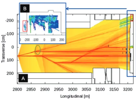
The phase-space of errant electron orbits compatible with magnet failure scenarios in different parts of LCLS-II is being projected over the accelerator layout to define where supplemental shielding panels and protection collimators are needed to contain the powerful beam. In the past such task would have been performed ’manually’ by comput-ing analytically or graphically the maximum kicks from dipoles and from other strong magnets.
Here we have applied the concept outlined in [12], based on Monte Carlo tracking of events over controlled magnet perturbations. Once configured, such method is flexible to changes and it can cope with the complex layout of beam-lines in LCLS-II, accounting also for secondary effects (e.g. over-powered dipole over-kicks the beam and well-behaved down-beam defocusing quadrupole sends it out of the beam-line due to the excessive transverse off -set), incorporating pre-existing alignment tolerances and even imposing linked failure restrictions due to common power supplies.
This technique has been paired with MadFLUKA code [11], which converts MAD survey output files into a beam-line geometry file that can be incorporated in
FLUKA, and also generating thenominaloptics. The
op-tics has then been modified to reflect thefailurelogics so that ray-traces can be drawn over the existing accelerator geometry by simulating a high number of events.
Figure 3 shows the phase-space of mis-steered rays in the beam-switchyard region for the three beam-lines in that area. In that simulation, custom latching and scoring were coded to identify which magnets caused beams to reach a specific section of the geometry. For example, the non-allowed events, marked with a red box, come from over-powering the dipole circled in green. In that case a collimator of optimized dimensions was immediately pre-scribed.
4 Re-use of current facilities
LCLS-II will mostly fit as-is in the existing SLAC infras-tructure, i.e. the historic 2-mile linac followed by the beam transfer hall (BTH), undulator hall (UH), main dump hall (MDH) and by the experimental halls that were built for LCLS. The latter sections were designed for 5 kW beams, while LCLS-II will send up to 240 kW through the same enclosures. Moreover, although the Linac is underground
Figure 3.Ray-Trace for LCLS-II beam switchyard.A)Top pro-jection of all rays, andB)cross-section projection at the end of BSY.
and has occasionally hosted high-power beams, LCLS-II accelerator will be installed near the vertical plane of most penetrations to the Klystron Gallery, which means that beam-losses in that segment of the machine could lead to substantial exposure in the upper occupied area.
4.1 Linac penetrations
There are about 450 penetrations and shafts connecting the Klystron Gallery where personnel will be present, to the underground linac, 8 m below. The axis of some pene-trations are almost aligned with the future vertical beam plane, and therefore they offer a direct line of sight for ra-diation to stream upwards. Moreover, most of these pen-etrations cannot be plugged as waveguides, helium sup-ply/return lines and cables will go through them, and be-cause some will be used to vent the Linac in case of acci-dental helium spills during access.
Thus, shielding configurations blocking just a fraction of the open penetration were studied. Simulation tests were numerous and included solutions with partial filling of the penetration cross-sections, or with local shielding over the beam-line, or with shielding caps at the klystron gallery, as well as combinations of the three concepts.
Finally, the last approach, i.e. cylindrical caps at the Klystron Gallery with exit routes for cables and waveg-uides, were adopted as the shielding solution for most used penetrations. The caps, shown in figure 4 are 1 m in diame-ter and have∼22 cm of iron plates and∼30 cm of concrete. With that shielding, accidental point-type full beam losses of up to 2 MW by any penetration would lead to dose rates in the gallery below 250 mSv/h, which is the design Limit at SLAC. For normal beam losses at a rate of 1 kW (this limit is controlled by the BCS), dose rates would not ex-ceed the 5μSv/h design limit for the Klystron Gallery.
Figure 4.Shielding caps for used penetrations
4.2 Overground beam transfer hall
The Beam Transfer Hall (BTH) crosses SLAC research yard at ground level. This building, made of reinforced concrete in 2006 for LCLS transfer line, has 1.8-m thick walls and a 1.2-m thick roof (except under the three ser-vice buildings, where it is also 1.8-m thick). Long ion chambers inside the building would shut the beam offfor losses in excess of 5 W in any 35 m section. This pro-tection guarantees dose rates by the external walls under 5μSv/h.
In LCLS-II normal beam losses are expected to top at about 1 W/m, and in accident cases, up to 2 MW could be lost at a point. Instead of retrofitting the long building ac-cordingly, fences at 5.5 m from the outer walls will be in-stalled, equipped with gates with access controls. Access to the service buildings will be restricted to LCLS opera-tion only, and tight monitoring will be deployed to ensure that sky-shine dose to other buildings is not significant.
4.3 High-power beam dumps
Three high-power beam dumps rated at 250 kW (1) and 120 kW (2) will be installed at the beam switchyard and at the end of the undulator lines.
As for the 250 kW dump, it will be installed inside of the existing 17-m long iron wall (the so-called muon shielding) that separates the switch-yard from the BTH. Samples of its (old) shielding blocks were sent out for chemical analysis, as being such a thick shielding, real-istic composition becomes essential to predict the residual dose rate for access of personnel during beam-off, as well as to compute the neutron fluence outside of the building enclosure. Moreover the muon wall will require limited reconfiguration to host the dump, including features that ease eventual dump retrieval and substitution, with mini-mal exposure to personnel and without generating contam-ination.
The two 120 kW dumps will be installed in the ex-isting LCLS pits at the end of the narrow main dump-hall
Figure 5.Detailed implementation of LCLS-II SXR for undula-tor damage studies
(MDH). Due to the substantial average power increase that represents LCLS-II, the walls would need to be augmented to prevent groundwater activation by high-energy neutrons generated at the two dumps, but neither is there free space inside MDH, nor is it feasible to patch the walls from the outside, as this building is underground. Instead, the lo-cation of the dumps within the pits was shifted, i.e. they will sit 30 cm higher and closer to the aisle. This will be achieved by lifting and rolling the dump-lines. More de-tails about this can be found in [10].
The average power on the dumps could be allowed to raise (e.g. in case of future Linac upgrades) if some amount of the steel in the dump pits is replaced by a tung-sten alloy. Such upgrade should be performed before any beam is sent to the high-power dumps, as in the future the area will be too activated to perform those works.
Substantial shielding will be added on top of the dumps, including not only steel but also an intermediate plate of concrete that will limit activation of MDH. With these modifications, the residual dose rate inside MDH is expected to remain below 50μSv/h after one hour cool-down time while the prompt dose to nearby accessible ar-eas will be a 100 times lower.
5 Further studies, machine protection vs.
radiation protection
lead-ing to higher losses. Finally, in FEL machines, collimators and undulators need special attention, as beam losses in the first are desired to avoid damage of the latter. Exten-sive simulations are required to verify that high-power can be handled and shielded in the collimators and that doses to the fragile undulators are minimal (fig. 5).
Acknowledgement
This work was supported by U.S. Department of Energy contract DE-AC02-76SF00515.
References
[1] M. Santana, L. Ge, Z. Li, C. Xu, C. Adolph-sen, M. Ross, M. Carrasco, Studies of Radiation Fields of LCLS-II Super Conducting Radio Frequency Cavities, International Journal of Modern Physics: Conference Series, Vol. 44 (2016) 1660209; DOI: 10.1142/S201019451660209X
[2] K. Ko et. al., SciDAC and the International Linear Collider, Petascale Computing for Terascale Acelera-tor, Proceedings of SciDAC 2006, Denver, Colorado [3] T.T. Böhlen, F. Cerutti, M.P.W. Chin, A. Fassò, A.
Fer-rari, P.G. Ortega, A. Mairani, P.R. Sala, G. Smirnov and V. Vlachoudis, The FLUKA Code: Developments and Challenges for High Energy and Medical Applications, Nuclear Data Sheets120, 211-214 (2014)
[4] A. Ferrari, P.R. Sala, A. Fassò, and J. Ranft,FLUKA: a multi-particle transport code, CERN-2005-10 (2005), INFN/TC_05/11, SLAC-R-773
[5] V. Vlachoudis,FLAIR: A Powerful But User Friendly Graphical Interface For FLUKA, Proc. Int. Conf. on Mathematics, Computational Methods & Reactor Physics (M&C 2009), Saratoga Springs, New York, 2009
[6] M. Santana Leitner, A method to efficiently simulate absorbed dose in radio-sensitive instrumentation com-ponents, Journal of Instrumentation YYY
[7] K. Flöttmann, ASTRA Manual, http://www.desy.de/ ~mpyflo/Astra_manual/
[8] M. Borland, Elegant: A flexible SDDS-compliant code for accelerator simulation, Technical Report, Ar-gonne National Lab., 2000, http://www.osti.gov/bridge/ product.biblio.jsp?osti_id=761286
[9] M. Borland, Elegant: A flexible SDDS-compliant code for accelerator simulation, Technical Report, Ar-gonne National Lab., 2000, http://www.osti.gov/bridge/ product.biblio.jsp?osti_id=761286
[10] J. C. Liu et al, Radiological Environmental Protec-tion for LCLS-II High Power OperaProtec-tion, these proceed-ings
[11] M. Santana-Leitner, Y. Nosochkov and T. Rauben-heimer, MadFLUKA Beam Line 3D Builder. Simula-tion of Beam Loss PropagaSimula-tion in Accelerators, Pro-ceedings of the 5th International Particle Accelerator Conference,MOPME040/ISBN 978-3-95450-132-8, Dresden (2014)
![Figure 1. Flair [5] rendering of the FLUKA model for nine fullcryomodules. Outer total fluence (un-normalized) from field-emission is overlaid in the vertical plane](https://thumb-us.123doks.com/thumbv2/123dok_us/8130792.1354990/2.595.58.287.81.231/figure-rendering-fullcryomodules-uence-normalized-emission-overlaid-vertical.webp)