ISSN 2348 – 7968
Performance of MIR-LMS algorithm for adaptive beam forming in
Smart Antenna
Kapil Dungriyal1, S.Ananad2 and D. Sriram Kumar3
1
Mtech Scholar, Dept. Electronics and communication Engineering National Institute of Technology (NIT) Tiruchirappalli, Tamil Nadu 620015, India
2
Research Scholar, Dept. Electronics and communication Engineering National Institute of Technology (NIT) Tiruchirappalli, Tamil Nadu 620015, India
3
Head of Department/Assistant Professor, Dept. Electronics and communication Engineering of National Institute of Technology (NIT) Tiruchirappalli, Tamil Nadu 620015, India
Abstract
In this paper a Matrix Inverse Robust Least Mean Square (MIR-LMS) algorithm is propose where we uses the sample Matrix Inversion (SMI) algorithm and ratio parameters to control the contribution of normalized product vectors in the weight upgradation process. The idea behind this proposed algorithm is that we not only consider the present error vector but also the previous one with normalized received signal whose initial weight is upgraded by the SMI algorithm for the weight upgradation process. When the proposed algorithm compares with standard one than we see the performance enhancement is there in MIR-LMS algorithm we find that the signal response is improved, the convergence rate is faster with less Brownian motion and it suppress the interference angle of arrival (AOA) and direct the beam towards the desired user angle of arrival (AOA).
Keywords: Matrix Inverse Robust Least Mean Square
(MIR-LMS), Robust LMS (R-LMS), Sample Matrix Inversion (SMI), Mean Square error (MSE), signal response, beam formin.
1. Introduction
The smart antenna system is the combination of an array of antenna with a signal-processing capability to transmit and receive in an adaptive, spatially sensitive manner. The smart antenna radiation pattern nullifies the interference (unwanted) signal angle of arrival and direct the beam towards the desired (wanted) signal angle of arrival, by this the capacity of the system is improved and this process also leads to maximize the Signal to Interference Ratio (SIR), indeed maximizes the throughput of the network.
2. LMS Algorithm
The smart antenna radiation pattern is shaped according to some adaptive algorithms. A very computationally efficient adaptive algorithm is the least mean squares (LMS) algorithm which is invented by
Stanford’s professor Bernard Widrow and PhD student Ted Hoff in 1959. .
y(t)=WHX(t) (1)
where y (t) is the array output.
The LMS algorithm estimates the gradient of the error signal, e (t), by employing the method of steepest descent. The error signal is defined as the difference between the desired signal and the output signal. [3]
e(t) =S(t) – y(t) = S(t) – WHX(t) (2)
When using the LMS algorithm, the set of weighting element is initially set to zero. That is Wo = 0 using an above equation error signal is generated by comparing y (t) with the desired signal S(t) and then this error signal is used to update the weight vector using equation [3]
W(t+1)=W(t)+μX(t)e*(t) (3)
where: μ is step size parameter or weight convergence parameter. It is a real valued positive constant whose value lies between zero and 1. For large value of μ, we have fast convergence but lower the stability around the minimum value. On the other hand, for small value of μ, we have slow convergence but with higher stability around the optimum value. The speed of convergence also depends upon the Eigen structure of Rxx for optimum weight μ satisfy the following conditions where λmax is maximal Rxx Eigen value [4]
0< μ < 2/ λmax (4)
ISSN 2348 – 7968
3. ALGORITHM DEVELOPMENT
A Matrix Inversion Robust Least Mean Square (MIR-LMS) adaptive algorithm was proposed for smart antenna application. The MIR-LMS is the combine of individual good aspects of Sample Matrix Inversion (SMI), Robust Least Mean Square (R-LMS)[1] and the Normalized Least Mean Square (NLMS) algorithm. The weight coefficients derived by SMI algorithm are set as initial coefficients and are updated by introducing Robust LMS and NLMS algorithm.
In practice, the signals are not known and the signal environment frequently changes so we require an adaptive processor which must continuously update the weight vector to compensate the varying condition of the channel, for that an optimal weight vector can be derived by the estimation of covariance matrix Rxx and the cross-correlation matrix rsx in a finite observation interval and then these estimates are used to obtain the desired vector. [2]
Rxx = (5)
rSX= (6)
and the optimum weight is
Woptm=RXX-1rSX (7)
time interval between N1 and N2 should be supposed to be less because if time interval is large then it will take more time in matrix inversion and the output signal will be obtained by
y(t) = WH X(t)
here we consider present and previous error signal for robustness which are as follows [1]
e(t) = S(t) – y(t)
e(t-1)= S(t-1) – y(t-1)
weight up gradation equation of the MIR- LMS algorithm is given below
W(t+1) = W(t) + μ[(γ1X(t)e*(t))/||X(t)||2 +
(γ2X(t-1)e*(t-1))/||X(t-1)||2] (8)
Likewise in R-LMS here ratio parameters γ1 and γ2 control the amount by which current product e(t)X (t) and the previous product e(t−1)X(t−1) contribute to the weight up gradation respectively. Let us introduce a notation for the normalized product vectors for future reference as:
ᴪ1=X(t)e*(t)/||X(t)||2 (9)
ᴪ2=X(t-1)e*(t-1)/||X(t-1)||2 (10)
There are some constraints placed on the selection of ratio parameters. The constraint on each ratio parameter is
0 ≤ γ1 ≤ 1
0 ≤ γ2≤ 1
These constraints prevent the current normalized product vector and the previous normalized product vectors from having a negative multiplier, which may alter the proper weight up gradation process. One additional constraint is given by equation:
γ1+ γ2 = 1
Putting γ1=1, γ2 =0 in equation 8 yield
W(t+1)=W(t)+μᴪ1
Substituting value of ᴪ1 from equation 9 in above equation results in
W(t+1)=W(t) + μX(t)e*(t)/||X(t)||2 (11)
which is weight up gradation equation of conventional MI-NLMS algorithm. Hence MI-MI-NLMS algorithm can be seen as a special case of MIR-LMS algorithm with
γ1=1,γ2 =0 using equation 9,10 in equation 8 produce
W(t+1)=W(t)+μ[γ1ᴪ1 +γ2 ᴪ2 ] (12)
The final weight vector up gradation equation of the MIR-LMS algorithm is estimated from equation 12
4. SIMULATION RESULTS AND DISCUSSION
For simulation of adaptive algorithm, MATLAB is used and array used is uniform linear array (ULA). In simulation we compare the MIR-LMS algorithm withother conventional algorithm with different ratio parameter.
ISSN 2348 – 7968
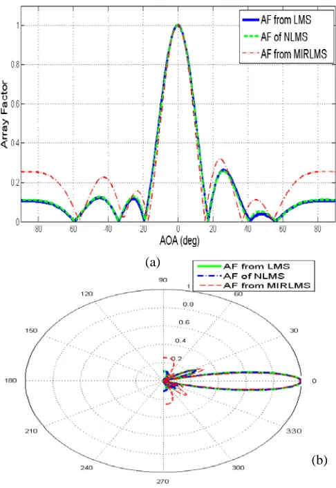
Figure 1: Signal response for ratio parameter γ1 = 0 and γ2 = 1
Figure 2: Beam forming capability of different algorithm with ratio
parameter γ1=0 and γ2=1, AOA of desired user: 0o and AOA of
interference at -20o, 40o (a) Rectangular plot (b) polar plot
Figure 3: Mean Square Error for ratio parameter γ1=0 and γ2=1
When we consider only the previous normalized product vector (ratio parameter γ1=0 and γ2=1) for weight up gradation then we see that our signal response is very poor, in beam forming although it maximizes the beam towards desired user AOA but not fully nullify the interference AOA. In MSE convergence rate is fast but very high Brownian motion is there.
Case 2: Ratio parameters γ1= 1, γ2= 0, Step size μ = 0.08, Number of element in array N=7, Desired angle = 0o, Interference angle=40o,-20o, iteration =100.
Figure 4: Signal response for ratio parameter γ1=1 and γ2=0
ISSN 2348 – 7968
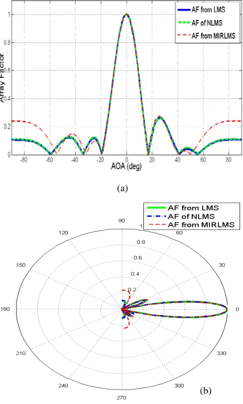
Figure 5: Beam forming capability of MIR-LMS for ratio parameter γ1=1 and γ2=0, AOA of desired user : 0o and AOA of interference : -20o ,
40o
(a) Rectangular plot (b) polar plot
Figure 6: Mean Square Error for ratio parameter γ1=1 and γ2=0
When we consider only the present normalized product vector (ratio parameter γ1=1 and γ2=0) for weight up gradation then we see that our signal response is poorer than NLMS algorithm response and in the end follow NLMS response while beam forming capability is good it direct the beam towards desired user AOA and nullify the interference AOA. In MSE convergence rate is faster with less Brownian motion.
Case 3: Ratio parameters γ1 = 0.5 γ2 = 0.5, Step size μ=0.08, Number of element in array N=7, Desired angle of arrival = 0o, Interference angle of arrival =40o,-20o, iteration =100.
Figure 7: Signal response for ratio parameter γ1=0.5 and
γ2=0.5
Figure 8 Beam forming capability of MIR-LMS for ratio parameter γ1=0.5 and γ2=0.5, AOA of desired user: 0o and AOA of interference:
40o,-20o (a) Rectangular plot (b) Polar plot. (a)
(b)
ISSN 2348 – 7968
Figure 8: Beam forming capability of MIR-LMS for ratio parameter γ1=0.5 and γ2=0.5, AOA of desired user: 0o and AOA of interference:
-20o
40o (a) Rectangular plot (b) Polar plot.
Figure 9 Mean Square Error for ratio parameter γ1=0.5 and γ2=0.5
When we give equal priority to both present and previous normalized product vectors (ratio parameter γ1=0.5 and γ2=0.5) than our signal response is improved as compared to NLMS algorithm, beam forming capability has improved and in MSE convergence rate fast Brownian motion is almost decreasing to zero.
4. Conclusions
In this paper, we implemented a new and effective array beamforming algorithm called Matrix Inverse Robust least Mean Square (MIR-LMS) algorithm which combines the individual good aspect of Sample
Matrix Inversion (SMI), Normalize LMS (NLMS) and Robust LMS (R-LMS) algorithm. Were the convergence rate, signal response and beamforming capability of LMS, NLMS is compared with proposed MIR-LMS algorithm with different ratio parameter and fixed step size with the help of MATLAB simulator. It shows that the convergence rate and Signal response (Array output) was improved and also the weight is updated in such a way that it suppresses the interference and direct the beam towards the desired direction
References
[1] R.L.Ali, “Robust Least Mean Square Algorithm for Adaptive Array Signal Processing”, wireless PERS commune, 2012. [2] M. Tariqul Islam, “MI-NLMS adaptive beam forming
algorithm for OFDM system”, Loughborough Antennas & Propagation Conference, 2008.
[3] Suchita W.Varade, “Robust algorithm for DOA estimation and adaptive beam forming for smart antenna application”, 2nd international conference on emerging trends in engineering and technology (ICETET-09).
[4] S.k.Imtiaj, “A comparative study of beam forming techniques using LMS and SMI algorithms in SA”, IEEE, 5th International Conference on Communications, Devices and Intelligent Systems (CODIS), 2012.
[5] Yang Qun, “Performance of LMS algorithm in SA”, IEEE 2010.
[6] M Yasin, Pervez Akhtar, “Implementation and Performance Analysis of Blind Beamforming
Algorithms on Adaptive Antenna Array”,2013 IEEE. [7] Xin Song,, Jinkuan Wang, Qiuming Li and Han Wang,
“Robust Constrained Constant Modulus Algorithm for Signal Steering Vector Mismatches”, 2012 IEEE.
[8] Jalal AbdulsayedSrar, “Adaptive RLMS algorithm for antenna array beam forming”, TENCON 2009.
[9] Surayan Mubeen, “Smart antenna its algorithms and implementation”, International journal of advanced research in computer science and software engineering (IJASCSSE-2012).
[10] Khyati R.Zalawadia, “Adaptive Beam Former Design using RLS Algorithm for Smart Antenna System”, International Conference on Computational Intelligence and Communication Systems, 2011.
[11] Shahera HOSSAIN, “Adaptive Beam forming Algorithms for Smart Antenna Systems”, International Conference on Control, Automation and Systems in COEX, Seoul, Korea,2008.
[12] “Antennas for Wireless Communications With MATLAB”, Frank B. Gross, PhD Senior Systems Engineer Argon ST Fairfax, Virginia [Book].
[13] S.C.Upadhyay, “Adaptive Array Beam forming using LMS Algorithm”, International Journal of Engineering Research & Technology (IJERT), 2013.
[14] Julie E. Greenberg, “Modified LMS Algorithms for Speech Processing with an Adaptive Noise Canceller”, IEEE TRANSACTIONS ON SPEECH AND AUDIO PROCESSING, VOL. 6, NO. 4, JULY 1998.
[15] Mahesh Godavarti, “Partial Update LMS Algorithms”, IEEE TRANSACTIONS ON SIGNAL PROCESSING, 2005.
ISSN 2348 – 7968
[16] Da-Zheng Feng, Zheng Bao, “Total Least Mean Squares Algorithm”, IEEE TRANSACTIONS ON SIGNAL PROCESSING, 1998.
[17] Zeeshan Haider, “Implementation and Investigation of different aspects of Beam Forming using LMS Algorithm on LES Antenna Array”, NESCOM (2009).
[18] Duan Li, “Study of Smart Antenna beam former based on Constant Modulus Algorithm”, 4th international conference on information and computing (2011).
[19] T.B.LAVATE, “Non blind and blind adaptive array smart antenna beam forming algorithms for W-CDMA mobile communication systems”, 2nd international conference on computer engineering and application (ICCEA-2010). [20] Shahera HOSSAIN, Mohammad Tariqul ISLAM and
Seiichi SERIKAWA, “Adaptive Beamforming Algorithms for Smart Antenna Systems,” International Conference on Control, Automation and Systems 2008.
[21] Said E. El-Khamy, Mohamed Shokry, “Enhanced Performance of Blind and Non-Blind Adaptive Arrays using Wavelet Beamforming,” 2013 IEEE.
[22] J.Homer, P.J.Kootsookos and V.Selvaraju, “Enhanced NLMS adaptive array via DOA detection,” IET Communications, 2007.