Article
Control of Hydraulic Pulse System Based on the PLC
and State Machine Programming
†Juraj PANČÍK 1*, Pavel MAXERA 2
1 Institute of Forensic Engineering, Brno University of Technology, Purkyňova, 464/118, Brno, 61200, Czech Republic; [email protected]
2 Institute of Forensic Engineering, Brno University of Technology, Purkyňova, 464/118, Brno, 61200, Czech Republic; [email protected]
* Correspondence: [email protected]; Tel.: +421-908-963-289
† This paper is an extended version of paper published in the International Conference Applied Electronics 2015, University of West Bohemia, Pilsen, Czech Republic, p.175-180., ISBN 978-80-261-0386-8.
Abstract: In the paper is described the control electronics for an industrial pneumatic – hydraulic system based on a low-cost PLC. The developed system is a hydraulic pulse system and it generates series of high pressure hydraulic pulses (max. 200 bar). We describe requirements, an overall concept of the embedded control system, user interface, security features and network connectivity. In the description of the software solution we describe implementation of hierarchical ordered program threads (multithreaded program) and main control state machine. At the conclusion, we describe the calibration method of the system and calibration curves and we present the schematic diagram and a photo of a functional prototype of the system.
Keywords: PLC programming, hydraulic pulse system, state machine programming,
1. Introduction
Our built-in control system for the hydraulic pulse system is based on the use of a modern low-cost programmable controller (PLC). A modern PLC allows you to program of parallel running programs (threads) each from them is programmed in for PLC programmers well-known as ladder diagram or as flow chart diagrams [1]. In our work we prepared for teh PLC robust, external errors free control program, for control of series high pressure hydraulic pulses based at one PLC. The PLC has ability to run of independent programming threads. Each thread in our case implements a specific activity (or task). Parallel running individual threads cooperate with each other so that the result is the creation of a reactive master control state machine [2].
2. Requirements for control of the hydraulic pulse system
Since we have limited space in this contribution, we are only trying to describe the need for creating a specific series of impulses.
2.1 Hydraulic pulse train
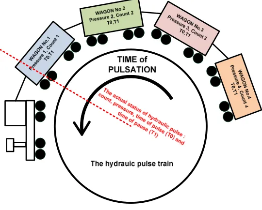
Our task was to create an embedded system for controlling the generation of hydraulic pulses series. The system controls up to four independent series each of them is defined by four adjustable parameters; the number of pulses (N), the maximum hydraulic pressure (p), the hydraulic pulse duration (T1) and the duration of the pause between pulses (T0). Each WAGON of this TRAIN has four passengers: N, p, T1, T2, see Figure 1, where WAGONs build a so-called "HYDRAULIC PULSE TRAIN". The hydraulic pulse train can cyclically repeat its orbit circle by set number of times (TRAIN SESSION). The number of WAGONs may range from 1 to 4. The embedded control system shall allow the user to set the output of the hydraulic pressure in the bar (0-200 bar), the set parameters of
the wagons, the number of wagons and the cyclic sessions of the train. It must allow system calibration (the dependence of the output hydraulic pressure in [bar] on the user's desired hydraulic pressure in [ADU] (ADU unit = Analog Digital Unit)) and it must ensure the generation of system and error messages.
Figure 1. Hydraulic pulse train – the schematic of sequence pulses control for hydraulic pulse system represented as train’s cyclic sessions
3. Hardware solution
3.1 Pneumatic - hydraulic parts
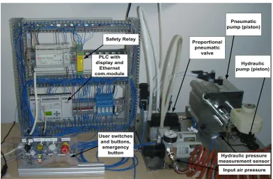
Figure 2. Schematic diagram of the developed hydraulic system and PLC based control system
Figure 3. The photo of the functional prototype of the hydraulic pulse system
This section is described by the scheme in Figure 2 and it was implemented on a cheap programmable logic controller type (PLC) Nanoline from Phoenix Contact [6] and on certain additional PLC's modules (used modules: analog input - output, user interface LCD display and keypad, USB, RS232 and Ethernet). Input and output logic of the digital signal has two levels 0 and 24V, analog outputs are in the range 0-10V, and analog inputs are in range 0-5V. The used PLC is built on the basis ARM 32 processor and its operating system offers running of several independent program threads simultaneously. The run of each thread is conditional on any particular value, e.g. by the value of the hardware input signal or by the program setting of value of the internal program flag. So parallel programming in the PLC is based on the running separated threads. Program for PLC can be identified with the parallel implementation of separate running and independent threads. This interesting ability of PLC's operating system we used in the creation of master program for control of hydraulic pulses.
3.3 User interface elements
The user interface consists from keypad, LCD display (4 rows x 20 characters), the manual switch between two basic modes of equipment (MANUAL mode and AUTO mode), the potentiometer for manual adjustment of output hydraulic pressure, the button to start of series hydraulic pulsation (PULSE mode), button to stop of pulses (the RESET button), security (or emergency) button to turn off the power of the appliance (EMERGENCY). The required values for WAGON and TRAIN parameters and the choosing of other equipment modes (e.g. calibration of the system) are entered from the in the PLC build keypad.
3.4 Electrical parts of system
Electrical parts of our system are formed by a 24V power supplies, safety relay [7], electrical and optical relays, switches, terminals and wires and it well be seen in Figure 2 and in Figure 3.
3.5 Safety features
The basis of ensuring the safety operation of high pressure pneumatic - hydraulic system is in use of certified safety relay [7]. The safety relay can in the case of detecting of system errors switched off the power for the whole electrical power part of the equipment (but not for control PLC). Key safety sensors are connected in the series. In the case of detection of problems with any media (hardware signals AIR or LIQUID) or detection of mechanical problems (hardware signals as DISTANCE ERROR or COVER EMERGENCY SWITCH), the series of connected contacts is interrupted, the safety relay responds and set the signal ERROR and switch off the power for hydraulic - pneumatic system in order to automatically reduce the output hydraulic pressure to minimum. The mechanical error with name DISTANE ERROR is generated by contact switch mounted near hydraulic cylinder and servers to indicate to attempt the generation of high pressure.
3.6 Network connectivity
Network connectivity of our control system is based on the PLC expansion module for connection to Ethernet LAN [8]. This communication module supports access to all program elements in the PLC multithreaded program (e.g. signals, flags, registers ...) via MODBUS protocol based on the TCP-IP protocols. As part of our PLC system we use also the MODBUS communication modules for both RS232 and USB. For our special purposes, we have developed the communication embedded server – the BUS and protocol converter between CAN bus (it uses the proprietary testbench protocol) and RS232 (MODBUS protocol) (Figure 2). The CAN converter works on the hardware module OLIMEX occupied with 8bit ATMEL AVR-CAN microcontroller [9]. The developed by protocol and BUS converter allows us to manage and to monitor hydraulic pulses unit even through CAN bus.
4. Software solution
The programming approaches for modern PLC are well described in [3][4]. Modern low-cost PLC, which allows running of several program threads gives the possibility to program main control state machine without having to create one long and complicated PLC program (ladder logic diagram or flowchart diagram). Each independent program thread can be initiated by hardware signal(s) (the PLC use 24V logic at input) or by internal programming flag with boolean data type (it can be set by another program thread).
4.2 List of PLC hardware inputs and outputs
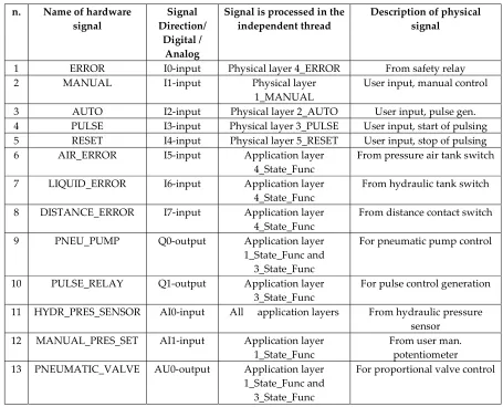
Table 1 lists of all digital and analog inputs and outputs are used in the project. Signals from the hardware inputs ERROR, WAIT, MANUAL, AUTO, PULSE and RESET are processing in the PLC by individual program threads (see Table 2) grouped in so called physical and application layer. Some hardware signal inputs are used for indicating of error’s cause in the safety power shutdown of the pneumatic - hydraulic system via safety relay (Figure 2, schematic diagram).
Table 1. List of PLC hardware inputs and outputs and their responsible processing layer
4.3 Physical layer threads
Threads of physical layer (Table 2) run in the PLC's operating system after their initializing by hardware input signals. Physical layer ensures processing of hardware signals and as a result this layer sets of outputs flags which are processed in the application layer. These outputs flags manage transitions between states in the master control state machine (literally by start or by stop of respective threads in the application layer). These programs threads also process of above mentioned inputs hardware signals and set of hardware output signals by align the required settling time or also
n. Name of hardware
signal Direction/ Signal Digital /
Analog
Signal is processed in the
independent thread Description of physical signal
1 ERROR I0-input Physical layer 4_ERROR From safety relay
2 MANUAL I1-input Physical layer
1_MANUAL User input, manual control 3 AUTO I2-input Physical layer 2_AUTO User input, pulse gen. 4 PULSE I3-input Physical layer 3_PULSE User input, start of pulsing 5 RESET I4-input Physical layer 5_RESET User input, stop of pulsing
6 AIR_ERROR I5-input Application layer
4_State_Func From pressure air tank switch 7 LIQUID_ERROR I6-input Application layer
4_State_Func From hydraulic tank switch 8 DISTANCE_ERROR I7-input Application layer
4_State_Func From distance contact switch 9 PNEU_PUMP Q0-output Application layer
1_State_Func and 3_State_Func
For pneumatic pump control
10 PULSE_RELAY Q1-output Application layer
3_State_Func For pulse control generation 11 HYDR_PRES_SENSOR AI0-input All application layers From hydraulic pressure
sensor 12 MANUAL_PRES_SET AI1-input Application layer
1_State_Func From user man. potentiometer 13 PNEUMATIC_VALVE AU0-output Application layer
1_State_Func and 3_State_Func
set of next parameters of elements of pneumatic or hydraulic hardware (e.g. delay of relays, setting time of input valve etc.).
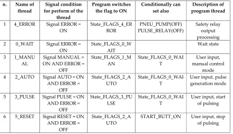
Table 2. List of implemented physical layer threads
4.4 Application layer threads
The start of running of the application layer threads (Table 3) are initiated by changes of program flags received from the physical layer. Some threads from this layer create of individual states in the master control state diagram (Figure 3). In addition, these program threads enable the realization of sub states. For example, thread 2_State_Func ensures to call of sub state 6_State_Func. This thread ensures the manually set of parameters in the hydraulic pulse train. Next thread underpins subroutine for user input interaction such the 22_State_Func. This sub state provides possibility manually input of calibration constants.
Table 3. List of application layer threads n. Name of
thread for perform of the Signal condition thread
Program switches
the flag to ON Conditionally can set also program thread Description of
1 4_ERROR Signal ERROR =
ON State_FLAGS_4_ERROR PULSE_RELAY(OFF) PNEU_PUMP(OFF) Safety relay output processing 2 0_WAIT Signal ERROR =
ON State_FLAGS_0_WAIT Wait state
3 1_MANU
AL ON AND ERROR = Signal MANUAL = OFF
State_FLAGS_1_M
AN State_FLAGS_0_WAIT manual control User input, mode 4 2_AUTO Signal AUTO = ON
AND ERROR = OFF
State_FLAGS_2_A
UTO State_FLAGS_0_WAIT User input, pulse generation mode
5 3_PULSE Signal PULSE = ON AND ERROR =
OFF
State_FLAGS_3_PU
LSE State_FLAGS_0_WAIT User input, start of pulsing
6 5_RESET Signal RESET = ON AND ERROR =
OFF
State_FLAGS_2_A
UTO START_BUTT_ON User input, stop of pulsing
n. Name of
thread perform of the thread Flag condition for Description of program thread, see Figure 4 Master control state diagram for hydraulic pulse system
1 0_State_Func State_FLAGS_0_WAIT =
ON AND ERROR = OFF WAIT STATE, Initialization of calibration constants, zeroing of the ATE pressure sensor 2 1_State_Func State_FLAGS_1_MANUAL
= ON AND ERROR = OFF MANUAL STATE, manual control of output hydraulic pressure via manual potentiometer 3 2_State_Func State_FLAGS_2_AUTO =
ON AND ERROR = OFF pulse train: WAGON parameters numbers of TRAIN AUTO STATE, setting of parameters for hydraulic WAGON and number of TRAIN SEASSON, manual calibration constants inputs (sub state: 22_State_Func) 4 3_State_Func State_FLAGS_3_PULSE =
Figure 4. Master control state diagram for hydraulic pulse system consists from 7 separate threads running in application layer, each thread represents individual state of pneumatic-hydraulic pulsing system and is described in Table 3.
4.5 Description of the master control state machine
The main control state machine (Figure 4) for hydraulic pulse system consists from 7 separate threads running in application layer, each thread represents individual state of pneumatic-hydraulic pulsing system and is described in Table 3. Transitions between states in application layer is controlled by the program flags and they are isolated from the hardware inputs signals (Table 1) processed by physical layer (Table 2). Thanks to this solution we met with reliable functions of high pressure hydraulic pulse system, with reliable answers to user inputs or to error status. We observed the reliable automatically generated ends of each pulsation cycle or hydraulic pulse train.
goes automatic to AUTO MODE (FLAGS_2_AUTO = ON, FLAGS_3_PULSE = OFF)
5 4_State_Func State_FLAGS_4_ERROR ERROR STATE, Safety relay determined, determination of the error source
6 5_State_Func State_FLAGS_5 Sub state of PULSE STATE, measurement of the maximum of the hydraulic pulse peak during PULSE
MODE (during the pause time and during the pulse time)
7 6_State_Func State_FLAGS_21_QSET Sub state of AUTO STATE, user setting of parameters for four TRAIN (T0, T1, COUNT, PRESSURE) 8 7_State_Func State_FLAGS_7 Sub state of PULSE STATE, actual modification of
4.7 Auxiliary functions
The control of pulses sequences according to saved parameters in the hydraulic pulse train ensures thread 7_State_Func in application layer which is called from the state PULSE (3_State_Func). The thread 6_State_Func ensures the users inputs for controlling of the actual content of hydraulic pulse train and is called from AUTO STATE (2_State_Func).
4.8 Input – output calibration of the system
The thread 6_State_Func ensures the manual input of calibration constants from user. The reason for calibration is simple: user works with pressure units in [bar] but PLC works with an internal representation of pressure in ADU units. The user calibration process is implemented within the MANUAL STATE, in the static mode (no pulse condition, manually controlled output hydraulic pressure). The user can obtain by measurements two calibration curves. The first calibration curve is adjustable characteristic between the output hydraulic pressure (measured with portable calibrated hand held hydraulic pressure measurement equipment from WIKA [10]) and the output voltage in ADU (measured via PLC itself) from the sensor output hydraulic pressure ATE PS60 (commercial produced hydraulic pressure sensor used in the cars, the manufacturer is ATE). In our case, we obtained a linear relationship, which leads to the linear equation (1) derived by regression analysis from the graph of the measured values:
(1)
The by calibration determined value of the constant AATE PS60 is 0.1021 [bar / ADU] and the value of the constant BATE PS60 is 4.8074 [bar] (Figure 5).
The second dependence is the static transfer function of the entire pneumatic - hydraulic system and its dependency output hydraulic pressure (in bar, measured by the same equipment [10]) depending on the values of the input voltage (measured in ADU units via PLC itself) for proportional pneumatic valve. Measurement leads to the next linear equation:
(2)
where the value of the constant ASYS is 0.053 [bar/ADU] and the value of the constant BSYS is 0.0626 [bar]. Both linear equations (1) (2) provide of four calibration constants, which user can enter in to the control system (in the thread 6_State_Func). Then, after calibration, according to the user entered value (therefore desired output hydraulic pressure in bar) is thus obtained at the output of pneumatic – hydraulic system as is required in both states – MANUAL and PULSE STATE.
Figure 6 Measured transfer curve between output of pneumatic - hydraulic system pressure and input of system (see equation (2))
4. Discussion
The developed by us pneumatic-hydraulic system is a one part in an industrial test bench. Our possible benefits are in the introduction of co-operating layers (physical layers and application layers) on a low-cost PLC platform (without the need for high-level programming like C++). This may be our possible contribution to education of young technicians. All necessary software solutions (running at “nanoNavigator” IDE (Integrated Development Environment) from Phoenix Contact [11]) are provided by authors for study purposes as supplementary material (the link see below). Mutually communicating threads can be study in the software simulator provided by nanoNavigator IDE and is not necessary to study or program with buy any PLC hardware.
5. Conclusions
We have built an embedded control system as a high-pressure hydraulic pulse control unit that can be calibrated, accurately, robustly and networked. This hydraulic impulse unit is part of a test machine that can be used in the industry for hydraulic parts testing. From point of view of software architecture, the control system is based on a basic low-cost PLC architecture and a set of parallel program threads. Each thread can be identified using a single logic scheme or schema. The PLC
multi-y = 0.1021x + 4.8074 R² = 1
0 20 40 60 80 100 120 140 160 180
0 200 400 600 800 1000 1200 1400 1600 1800
P W IK A [b ar ]
P ATE PS60 [ADU]
𝑃
𝑊𝐼𝐾𝐴[𝑏𝑎𝑟]
= 𝐴
𝐴𝑇𝐸 𝑃𝑆60× 𝑃
𝐴𝑇𝐸 𝑃𝑆60[𝐴𝐷𝑈] + 𝐵
𝐴𝑇𝐸 𝑃𝑆60y = 0.053x - 0.0626 0 50 100 150 200 250
0 500 1000 1500 2000 2500 3000 3500 4000 4500
P W IK A [b ar ]
thread program is designed as one large and opaque linear program, but as a group of mutually communicating PLCs, which ultimately form one master control state diagram. The cost of the described industrial networked control system with industry standard 24 V optoelectronic insulated interfaces does not exceed 300 Euros, all control systems (certified safety relay, PLC + electrical parts) amount to € 1,000.
Supplementary Materials: The following are available online at www.mdpi.com/xxx/ Suplement materials.zip, Figures (directory: \Figures\ ) and software solutions for PLC (\SW for PLC Nanoline IDE Phoenix Contact\140427_AUTO_state_ver.3.Nano).
Funding: This research received no external funding
Conflicts of Interest: The authors declare no conflict of interest.
References
1. Parr, E.A. Programmable Controllers: An Engineer's Guide. New York, USA : Newnes,2003. 2. Kopetz, H. Real-Time Systems. New York, USA : Springer, 2011
3. Introduction into IEC 1131-3 and PLC open. The Application of IEC 61131 to Industrial Control: Improve Your Bottom Line Through High Value Industrial Control Systems, IEE Colloquium on. Van der Wal, E. 1999. London, UK : The Institution of Electrical Engineers
4. Lewis, R.W. Programming Industrial Control Systems Using IEC 1131-3. New York, USA : The Institution of Electrical Engineers, 1996
5. Merritt, H. E. Hydraulic Control Systems. Cincinnati, Ohio : John Wileys and Sons, 1967
6. Phoenix Contact. Nanoline Base Units. Phoenix Contact . [Online] [Cited: 13.9.2018] https://www.phoenixcontact.com/online/portal/us?1dmy&urile=wcm%3apath%3a/usen/web/main/produ cts/list_pages/Programmable_controllers_P-21-01-01/df42a2d9-f542-45d4-8033-15f0265ea3cb
7. —. Safety relays - PSR-SCP- 24UC/ESAM4/3X1/1X2/B - 2900509. [Online] [Cited: 13.9.2018]
https://www.phoenixcontact.com/online/portal/us?uri=pxc-oc-itemdetail:pid=2900509&library=usen&pdfmode=direct&pdflanguage=en.
8. —. Communication module - NLC-COM-ENET-MB1 - 2701124. [Online] [Cited: 13.9.2018]
https://www.phoenixcontact.com/online/portal/us?uri=pxc-oc-itemdetail:pid=2701124&library=usen&pcck=P-21-03-03-01&tab=1.
9. OLIMEX. AVR-CAN development board based on AT90CAN128. [Online] [Cited: 13.9.2018] https://www.olimex.com/Products/AVR/Development/AVR-CAN/.
10. Wika Instruments . Hand-Held Pressure Indicator Model CPH 6200. [Online] [Cited: 13.9.2018] http://www.wika.us/upload/DS_HPCPH6200___CPH6200_S2_en_us_17152.pdf
11. Phoenix Contact. Software - NLC-NAV-01 – 2701221,. nanoNavigator software. [Online] [Cited: 13.9.2018]