IMPROVE THE FLOW OF ENERGY IN TRANSMISSION
LINE THROUGH UPFC
1B.VAMSI,2 K.RAJANI
1PG Scholar, Department Of EEE,Sri Sai Educational Society's Group of Institutions, Kodad. 2Assistant Professor, , Department Of EEE,Sri Sai Educational Society's Group of Institutions, Kodad.
Abstract:
This project concentrates on
FACT device UPFC which is used for
power flow control in the transmission
side. With the growing demand of
electricity, it is not possible to erect new
lines to face the situation. Flexible AC
Transmission System (FACTS) makes use
of the thyristor controlled devices and
optimally utilizes the existing transmission
network. One of such device is Unified
Power Flow Controller (UPFC) on which
the emphasis is given in this present work.
Real, reactive power, and voltage balance
of the unified power-flow control (UPFC)
system is analyzed. A novel coordination
controller is proposed for the UPFC. The
basic control method is such that the shunt
converter controls the transmission line
reactive power flow and the dc-link
voltage. The series converter controls the
real power flow in the transmission line and
the UPFC bus voltages. Experimental
works have been conducted to verify the
effectiveness of the UPFC in power flow
control in the transmission line. The
simulation
model
was
done
in
MATLAB/SIMULINK ,platform.
Keywords: FACTS, IGBT, Reactive powe r
balance, Real power balance, Series
converter, Shunt converter, Unified
Power-Flow Controller (UPFC), Voltage balance
.I.INTRODUCTION:
The power transmitted over an ac transmission line is a function of the line impedance, the magnitude of sending-end and receiving-end voltages, and the phase angle between these voltages. Traditional techniques of reactive line compensation and step-like voltage adjustment are generally used to alter
can internally generate reactive power for, and also exchange real power with, the ac system. The Unified Power Flow Controller (UPFC) is a member of this latter family of compensators and power flow controllers which utilize the synchronous voltage source(SVS) concept for providing a uniquely comprehensive capability for transmission system control. Within the framework of traditional power transmission system concepts, the UPFC is able to control, simultaneously or selectively, all the parameters affecting power flow in the transmission line. Alternatively, it can provide the unique functional capability of independently controlling both the real and reactive power flow in the line. These basic capabilities make the Unified Power Flow Controller the most powerful device presently available for transmission system control. Unified power flow controller (UPFC) is a member of FACTS family. It is a combination of Static synchronous compensator (STATCOM) and Static synchronous series compensator (SSSC) coupled via a common dc-link, to allow bi-directional flow of real power between the series output terminals of the SSSC and the shunt output terminals of the STATCOM. The UPFC, by means of angularly unconstrained series voltage injection, is able to control the transmission line voltage, impedance and angle or the real and reactive power flow in the line. Also the problem of low-frequency power swings is a matter of concern for power systems engineers. As it is becoming increasingly important to fully utilize the existing transmission system assets, proper attention should be given to the enhancement of utilizing the transmission capacity by damping of the power swings. Flexible AC transmission system (FACTS) devices are found to be very effective for this purpose. A FACTS device should have an adequate margin of variable compensation for effective damping of power swings. Therefore, while
planning for FACTS controllers, the damping effect per MVar and the control cost should be taken into consideration. The damping provided by FACTS devices offers the means to reduce the inhibiting effects of the oscillations or swings. But the outputs of these FACTS devices should be restricted by the limits within their working conditions. Notwithstanding, low frequency oscillations are detrimental to the goals of maximum power transfer and optimal power system security.
II.SYSTEM OVERVIEW
The first FACTS installation was at the C. J. Slatt Substation in Northern Oregon. This is a 500kV, 3-phase 60 Hz substation, and was developed by EPRI, the Bonneville P.
Series co mp en s atio n
In series compensation, the FACTS is connected in series with the power system. It works as a controllable voltage source. Series inductance exists in all AC transmission lines. On long lines, when a large current ows, this causes a large voltage drop. To compensate, series capacitors are connected, decreasing the effect of the inductance.
Sh u n t co mp en s atio n
In shunt compensation, power system is connected in shunt (parallel) with the FACTS. It works as a controllable current source. Shunt compensation is of two types:
•Sh u n t cap acitiv e co mp en s atio n :
shunt capacitor is connected which draws current leading the source voltage. The net result is improvement in power factor.
•In d u ctiv e co mp en s atio n :
This method is used either when charging the transmission line or, when there is very low load at the receiving end. Due to very low, or no load very low current ows through the transmission line. Shunt capacitance in the transmission line causes voltage amplification(Ferranti Effect). The receiving end voltage may become double the sending end voltage (generally in case of very long transmission lines). To compensate, shunt inductors are connected across the transmission line. The power transfer capability is thereby increased depending upon the power equation.
The concept of Flexible AC transmission system has been proposed in 1995, which is called FACTs. The basic idea of FACTs is installing the power electronic devices at the high-voltage side of the power grid to make the whole system electronically controllable. The advances achieved in the high power semiconductor devices and control technology makes the foundation of the development of FACTs. The FACTs devices are able to provide active and reactive power to the grid rapidly. The power compensation achieved by FACTs devices could adjust the voltage of the whole system and the power flow could be satisfactorily controlled. Many works are carried out, related to the real and reactive power control in transmission line and the direct power control. The dynamic behaviour of two different flexible ac transmission system devices; the interline power-flow controller (IPFC) and the unified power-flow controller (UPFC) in a benchmark system. The small-signal model of the interline power-flow controller is developed and validated using detailed electromagnetic transients
simulation.
2.1 Th e Unified Power Flow Controller (UPFC) The basic conception of the UPFC was proposed by Nabavi-Niaki and Iravani in 1996[4].The Unified Power Flow Controller(UPFC) was devised for the real-time control and dynamic compensation of ac transmission systtem, providing multi-functional exibility required to solve many of the problems facing the power delivery industry.
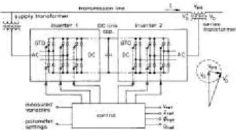
The UPFC is made up of two voltage source controllers sharing the same capacitor at their dc voltage controlled side. One voltage source controller is in parallel with one side of a transmission line and the other voltage source controller in the UPFC is in series connect to the other side of the same transmission line. The basic structure of the UPFC is shown in the Figure 1. The UPFC can simultaneously control the active and reactive power flow and voltage magnitude. However it has little effect on voltage angle.
UPFC can control the balance of the transmitted power between parallel lines and, as such, can optimize the use of the transmission grid for all parallel power flows. A one-wire schematic of a transmission-line system equipped with a UPFC is given in Fig.2
Fig. no:2 Basic structure of UPFC
A UPFC is connected to the transmission line by coupling transformers, both with a shunt and with a series connection. The UPFC consists of two ac/dc converters, the ac sides connected to the shunt and series connection with the transmission line, and the dc sides connected back to back. UPFCs are typically built with voltage-sourced converters, having a capacitor as (limited) dc energy storage. The control scheme and comprehensive analysis for a unified power flow controller (UPFC) on the basis of theory, computer simulation, and experiment. This developed theoretical analysis reveals that a conventional power feedback control scheme makes the UPFC induce power fluctuation in transient states. The conventional control scheme cannot attenuate the power fluctuation, and so the time constant of damping is independent of active and reactive-power feedback gains integrated in its control circuit. An advanced control scheme which has the function of successfully damping out the power fluctuation. A UPFC rated at 10 kVA is designed and constructed, which is a combination of a series device consisting of three single-phase pulse width modulation (PWM) converters and a shunt device consisting of a three phase diode rectifier. 2.2Po wer-Flo w Co n tro l
The real, reactive power, and voltage balance of the
III.PROPOSED SYSTEM
The first generation of the FACTs devices. In this period, the typical devices are including tap changing and phase changing transformer, synchronous generator and series capacitors. Except the series capacitors, which could also be called capacitor bank, others are dynamic devices. These devices are mainly controlled at the generation sideof the power grid and the cost is typically expensive. When talk about the series capacitors, the drawback of this device could hardly be omitted. Since the device is made up of many fixed-capacitance capacitors, it could hardly be controlled to give the real not-fixed capacitance to the grid. The second generation of the FACTs devices. It could be classified into two categories: thyristor-based devices and fully-controlled devices based compensator. The thyristor is called half controlled device, because it can only be controlled to switch on but notto cut-off. Static Var Compensator (SVC) and Thyristor-Controlled Series Capacitor (TCSC) are included in this category. The fully controlled devices mainly involve GTO etc. The Static Compensator (STATCOM), Solid State Series Compensator (SSSC), Unified Power Flow Controller (UPFC) and HVDC- Voltage Source Converter (HVDC-VSC) are included in this group.
3.1Pro b lem s o lu tio n
AC transmission lines form the backbone of the electricity grid in most countries and continents. The power flow will follow the path of least impedance and is uncontrollable, unless active grid elements are used. To enhance the functionality of the ac transmission grid, flexible ac transmission systems
(FACTS) support the transmission grid with power electronics. These devices offer a level of control to the transmission system operator. A unified power-flow controller (UPFC) is the most versatile of these FACTS devices. A transmission line equipped with a UPFC can control the balance of the transmitted power between parallel lines and, as such, can optimize the use of the transmission grid for all parallel power flows.
3.2Proposed controller
3.2.1 Series and Shunt controllers
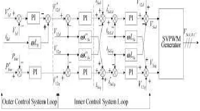
The shunt converter of the UPFC controls the reactive power flow in the transmission line and dc-link voltage. The control diagram for the shunt part of the UPFC is shown in Fig 4. The control scheme is composed of two loops the outer loop and the inner loop. The outer loop generates the current reference with coordination control, while the inner current loop makes the shunt converter output the necessary currents. The control system is based on the synchronous rotating frame as mentioned before. The -axis current is controlled to manage the dc-link voltage and balance the real power of the UPFC. The -axis current is controlled to manage the transmission-line reactive power flow. The decoupled control system has been employed to achieve simultaneous control of the shunt converter input current. Coordination control schemes are applied in both transmission-line reactive power flow and dc-link voltage control to obtain better dynamic performance. In the axis coordination control scheme, the transmission-line reactive power-flow variation reference is added to the reactive power-flow PI regulator output with a gain 2/3V1d. So the shunt converter can generate an appropriate amount
of reactive power to compensate the reactive power-flow change with a quick response. Further, the inner control system loops are fast-acting PI controllers and ensure fast supply of both the series converter real power demand and the reactive power needed for reactive power-flow control by the shunt
converter.
The series converter of the UPFC provides simultaneous control of the UPFC bus voltage and real power flow in the transmission line. To do so, the series converter injected voltage is decomposed into two components. The transformation is the same as that used in shunt converter control. The axis injected component controls the UPFC bus voltage. The axis injected component controls the transmission-line real power flow. The detail of this control scheme is shown in Fig 5. The whole control system is composed of two loops as it is in the shunt converter. The outer loop generates the reference voltage signals for the inner loop with coordination control. A current feed forward is added to the -axis outer loop to compensate the voltage changes across the line impedance when there is a power flow change. The inner control loop is a typical voltage current double-loop control scheme for inverters. The same decoupled control strategy as mentioned in is applied here. With this method, the UPFC bus can be controlled directly and good performance is expected.
Fig. no : 5 Series Controller
IV. Simulations And
Results
An experimental UPFC system has been built to test the power control in transmission line. Recent advances in high-voltage IGBT technology allow for higher switching frequency with lower loss, and this allows for practical implementation of PWM control for high-power converters. So in the experiment, both the shunt converter and the series converter have been built as a three-phase PWM converter with IGBT as the power device. The UPFC device is inserted into a transmission line, and with the
help of the UPFC, the power flow in the transmission line can be controlled effectively while maintaining the UPFC bus voltage constant. The parameters of the whole systems are given below:-
Fig .6 Tran s mis s io n lin e with o u t UPFC
Plo t -1
Plo t -2
Plo t -3
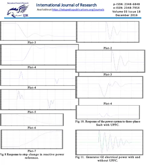
Fig .7 Response of power system to step ch an g es in tran s mis s io n lin e real p o wer referen ce.
Plo t -1
Plo t -3
Plo t -4
Plo t -4
Plo t -5
Plo t -6
Plo t -7
Fig 8 Response to step ch an g e in reactiv e p o wer referen ce.
Fig 9. Response of the power system to th ree -p h as e fau lt with o u t UPFC.
Plo t -1
Plo t -2
Plo t -3
Plo t -4
Fig 10. Response of the power system to three-phas e fau lt with UPFC.
Fig 11. Generato r G2 electrical p o wer with an d with o u t UPFC.
V.Conclusion
flow changes if the UPFC bus voltage is constant. The UPFC bus voltage can be controlled both from the sending side and from the receiving-end side.
REFERENCES
[1] L. Gyugyi,"Direct power control of series converter of unified power-flow controller with three-level neutral point clamped converter",IEEE Trans. Power system., vol. 27, no. 12, December 2012.
[2] L. Gyugyi, C. Schauder, S.Williams, T.
Rietman, D. Torgerson, and A. Edris,"The unified power flow controller: A new approach to power transmission control",IEEE Trans. Power system,vol. 11, no. 2, pp. 221227, Mar. 1996. [3] A. R.Munoz and T. A. Lipo, "Control and analysis
of a unified power flow controller" ,IEEE Trans. Power Electron., vol. 14, no. 4, pp. 683689, Jul.1999.
[4] G. Pellegrino, R. I. Bojoi, P. Guglielmi, and F. Cupertino, "An improved upfc control for oscillation damping", IEEE Trans. Ind. Appl., vol. 46, no.5, pp. 19701978, Sep./Oct. 2010. [5] T. Hoshino and J.-I. Itoh, "Output voltage
correction for a voltage source type inverter of an induction motor drive", IEEE Trans. Power Electron., vol. 25, no. 9, pp. 24402449, Sep. 2010.
[6] L. Chen and F. Z. Peng, "Power-flow control performance analysis of a unified power-flow controller in a novel control scheme" IEEE Trans. Power system., vol. 23, no. 2, pp. 574580, Mar. 2008.
[7] Mariusz Jankowski and Grzegorz Jabonski,"Effects of unified power flow controllers on transient stability", INTL JOURNAL OF POWER SYSTEM, 2012.
AUT HOR’S PROFILE:
1. B.VAM SHI
PG Scholar, Department Of EEE. Gandhi Academy Of Technical Education, Ramapuram (kattakommu Gudem), Chilkur(M), Kodad, Telangana 508206.
2. K.RAJANI