645
Effect of surface coatings of polystyrene pattern on surface
morphology and mechanical properties of Al-Si eutectic casting
Shafeen p1 Dr. N. M. Nagarajan 2
1
Final Year M.Tech in Manufacturing Engineering, KMCT College of Engineering, Calicut, Kerala Email: [email protected] Mob: +919947131410
2
Professor, Dept. of ME, KMCT College of Engineering, Calicut, Kerala Email: [email protected], Mob: +91 9895281423
Abstract— Full mould casting process uses a polystyrene pattern, which evaporates upon the contact with molten metal to form a cavity for the casting. The process is also known as expendable pattern casting or lost pattern casting. It has become one of the most important casting processes for ferrous and nonferrous metals, particularly for the automotive industry. In this process pattern is kept inside a sand mould. As the metal is poured, the foam vaporizes, and the metal takes its shapes. The gas from the foam flees through the sand. Here, Al-Si eutectic alloy is used to produce casting. Aluminum silicon eutectic alloy generally called L-M 6 containing 10 to 13 percent by weight of silicon. Due to its good casting properties, high strength to weight ratio and excellent corrosion resistance, this alloy finds applications in automobile, aircraft and marine industries. The present work is undertaken to evaluate the evaporative pattern casting process with surface coating on the pattern by using a polystyrene cutting machine. The work is carried out by using varnish, clay, and graphite coatings on the pattern to produce casting with good surface finish. In order to get good strength of casting, modification using sodium modifier is added into Al-Si melt. Test result reveals that polystyrene pattern is used to produce complicated profiles. Graphite coating on the pattern gives the best surface finish in the casting among the coating materials used. Modification treatment using sodium salts found increase in mechanical properties such as ultimate tensile strength, and hardness. The optimum values are obtained at 1.5% by weight addition of sodium compound
I. INTRODUCTION
Full mould casting is one of the modern and hybrid casting processes, which aims to minimize the production cost, and is capable of producing complex shapes with less effort in pattern making. The foam patterns were first patented by H F Shroyer in the year 1958. Full mould casting makes use of patterns made from evaporative materials like foam. The pattern material gets evaporated due to the heat of molten metal as it gets filled.
In full mould castings, evaporative polystyrene is used to prepare the complete pattern, including the gates and risers. A refractory surface coating is applied to the entire assembly. After the coating gets dried, the entire foam pattern assembly is kept on a vented flask for the making of moulds. Subsequently, molten metal is poured into the sprue, which further reprises the foam polystyrene. As soon as it enters inside the entered metal solidifies and reproduces the size and shape of the used pattern perfectly to get the desired casting in this process.
In this project work Al-Si eutectic alloy is used for casting production. Al-Si alloys generally have excellent casting and very good resistance to corrosion. LM6 is a eutectic alloy of Al-Si (LM 6) which containing 10-13% by weight of silicon. Aluminum has a density of only 2.7 gram/cc, approximately one third as much as steel. As the density of silicon is 2.3 gram/cc, it is one of the few elements that may be added to aluminum without loss of weight advantages. Mechanical properties of Al –Si eutectic alloys can be improved by the application of surface coatings and modification. Graphite powder, clay powder, and varnish are used as the surface coater in this work. The process of adding sodium fluorides or other alkali fluorides to the molten metal to improve the mechanical properties is termed as modification.
II. PROCESS DETAILS
A.FABRICATION OF HOT WIRE FOAM
CUTTER
Hot wire foam cutter developed is a tool used to cut polystyrene as shown in Figure 1. The main part of the device is a thin metallic wire, is heated via electrical resistance to approximately 100̊ C. As the wire is passed through the material to be cut, the heat from the wire vaporizes the material just in contact.
646 table, electrical unit, cutting wire, circle cutting
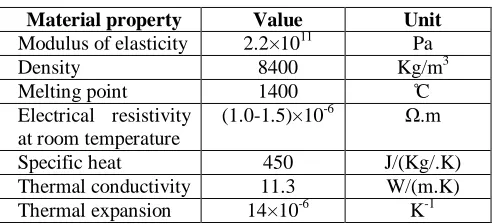
attachment, scale with adjusting arm. Properties of the wire are given in table 1.
Table 1: Properties of cutting wire
Material property Value Unit
Modulus of elasticity 2.2×10¹¹ Pa
Density 8400 Kg/m3
Melting point 1400 ̊C
Electrical resistivity at room temperature
(1.0-1.5)×10-6 Ω.m
Specific heat 450 J/(Kg/.K)
Thermal conductivity 11.3 W/(m.K)
Thermal expansion 14×10-6 K-1
In cutter, cutting action is carried out by heating the cutting wire. Joules law of heating is the working principle between the foam cutter machines. Joules law is the process by which the passage of an electric current through a conductor releases heat. The amount of heat released is proportional to the square of the current, and the time.
H = I2RT
H= Heat energy
I= Current passing through the wire
R= resistance of the wire
T= time taken
Polystyrene material is evaporated due to the passing quantity of current through the wire. The electrical system contains a step down transformer which transforms the 230v main supply to 12v supply; a volt meter is connected to the transformer. Regulators can again controlling the voltage. In this project 4.5 V is used for the cutting purpose.
The temperature requirement is calculated by equating heat energy to electrical energy.
H= m × s × t
m= mass of the wire
s= specific heat
t= temperature
H=I2RT
H= m × s × t
I2RT= m × s × t
t = I2RT/ (ms)
Hence t can be found out. In the present work t is varied from 70̊C to 120̊C by using regulator.
Figure 1: Hot wire foam cutter machine
B. POLYSTYRENE PATTERN MAKING
Rectangular block shape pattern is made by polystyrene material. The standard dimensions are marked on the thermo cool and the pattern is cut by using hot wire foam cutter. Then the complete pattern, including the gates and risers are assembled with glue, forming a cluster. Then the entire foam cluster is covered with surface coatings, such as graphite powder, varnish, and clay powder. The coatings act as a barrier between metal and sand so that the molten metal does not penetrate or cause sand erosion during pouring. After the coatings dries, the cluster is placed into a flask and backed up with bonded sand. After filling of sand the mold is ready for pouring.
C.MODIFICATION
Mechanical properties of Al –Si eutectic alloys can be improved by modification using sodium. The chemical composition of Al-Si alloy known as L-M 6 is given in table 2.
Table 2: General composition of LM-6 alloy
Cu <0.1
Mg <0.1
647
Fe <0.6
Mn <0.5
Ni <0.1
Zn <0.1
Pb <0.1
Sn <0.05
Ti <0.2
Al 88-85
In the unmodified state, Al –Si eutectic alloys contain silicon phases in the form of large plates with sharp sides and edges. Al-Si alloys containing more than about 12% Si exhibit a hypereutectic microstructure normally containing primary silicon phase in a eutectic matrix. Cast eutectic alloys with these silicon show low strength and ductility because of the coarse plate-like nature of the Si phase that leads to premature crack initiation and fracture in tension. Similarly, the primary silicon in normal hypereutectic alloys is usually very coarse and imparts poor properties to these alloys. Therefore, alloys with a predominantly eutectic structure must be modified to ensure adequate mechanical strength and ductility. Modification does break up the needle like silicon flakes within the grain and changes it to the fine dispersed form, even though it does not actually refine the grain size of the metal. The globules of modified structure are seen, to be the ends of silicon fibers which form an inter network. It is this transformation which is responsible for the enhanced properties associated with modified Al- Si casting. Group IA and IIA elements (Na, Mg, Ca, Sr) are effective modifiers of Al-Si eutectic alloys. Of all theses, sodium is the most effective in producing a fine uniform fibrous structure so sodium is introduced here.
D.MOULDING TECHNIQUES
Since LM –6 alloys has good cast ability and suitable for any type of mould, Green sand moulding and natural sand moulding are used. Natural sand moulds are having high permeability and fairly low green strength which is best suited for theses alloy. The properties of the molding sand used are given in table 3.
Table 3: Properties of molding sand
Grain fines AFSNO 70
Clay content 5%
Moisture content 16%
Green compression strength 1Kg/cm2
E. MELTING
Al–Si alloys with varying percentage of modification agent were prepared by melting in a graphite crucible in a high speed electrical furnace and the melt was held at 760°c in order to attain homogeneous composition.
To achieve sound casting the following chemicals are added.
Coverall flux (containing various salts likes alkalis chlorides and alkali fluorides) is used to prevent oxidation of molten metal.
Grain refiner is used to produce a fine grain structure. Grain refinement improves resistance to hot tearing, decreases the porosity and increases mass feeding. In this work, ‘nucleant-2’ grain refiner is used.
Degassing agents are added to remove the dissolved gases.
When the required temperature level in the furnace is reached, measured quantity of charge, in the form as scrap and ingot metal, is kept into it. When the charge becomes pasty condition coverall flux is sprinkled over its surface at a rate of 5gr/kg. The crucible should have sufficient temperature to keep the temperature of the melt from falling. Again coverall flux is added to the melt surface at a rate of 5gr/kg. After attaining the maximum temperature, melt is degassed and grain refined on a falling temperature, each adding at a rate of 2.5gr/kg. Both of them are plunged into the molten metal using a perforated plunger and kept under the melt till the bubbling action ceases. This process is called chemical treatment. On completion of the bubbling action, the surface flux cover of the melt is rabble and skimmed cleanly. A layer of modification compound is added to the clean melt surface from 0-2% by weight at a temperature about 760̊c. It is then poured into the mould without any delay.
F. PROFILED CASTING
A mermaid statue with complicated profile has been made using graphite coated polystyrene pattern and casting has been made using the pattern. The profiled casting is shown in figure 2.
Figure 2: Mermaid statue casting
648 In this project work, mechanical properties of test bar
casting such as surface roughness test, uniaxial tensile strength and hardness have been evaluated.
1. Surface roughness of casting is found out by using Profilometer. In this test, the specimen has been place in the profilometer. With the help of probe sensor the roughness has been checked and is shown in computer interface.
2. Ultimate Tensile strength is found out using universal testing machine (U T M).
3. Hardness number is found out using Rockwell hardness tester. It gives the resistance of test bar to plastic deformation.
III. RESULTS & DISCUSSIONS
A. POLYSTYRENE CUTTING MACHINE
Design and fabrication of pattern cutting unit with electrically heated nichrome wire has been developed. By using the hot wire foam cutter, patterns with smooth profile have been carved.
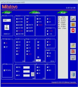
B. SURFACE ROUGHNESS OF PATTERN
Various coatings over the patterns such as graphite, clay, and varnish are applied. Castings have been produced, and the values in computer interface are given in Figures 3,4,5 and 6. Surface roughness has been checked with Profilometer. a bar chart is also given for clear understanding. The roughness found to be 3.92 micrometer for graphite coating, 7.65 micrometer for clay coating, 8.51 micrometer for varnish coating and 22.5micrometer for patterns without coating respectively.
From the figure 7 it is found that castings with high surface finish have been obtained using graphite coating on the polystyrene pattern. Other types of coating, castings with surface finish are much lower. As graphite is having high fusion point with lubricating properties, the surface coating on pattern is found to be very smooth.
From these values we can conclude that, the graphite coated pattern provides good surface finish on castings. While comparing with other coating materials
Figure 3: Profilometer value for graphite coated pattern
649
Figure 5: Profilometer value for varnish coated pattern
Figure 6: Profilometer value for pattern without coating
0 5 10 15 20 25
Graphite coated pattern
Clay coated pattern
Varnish coated pattern
Pattern without coating
R
ou
gh
n
e
ss
µ
m
Coating Variables
Figure 7: Effect of coating over roughness
C. STRENGTH
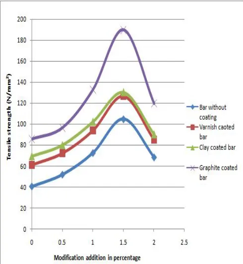
The results on strength obtained from the test bar produced with different coatings are shown in Table 4. It is found that castings from graphite coated patterns gives highest strength.
As graphite is having high fusion point with lubricating properties, so there is no more reactions occurred during pouring process. From the investigation the relation between tensile strength and modification addition is shown in fig 8. In unmodified alloy the silicon is in the form of large plates like structure with sharp edges. So whenever a formation of crack, that will propagate at a faster rate. But by applying modification the silicon structure becomes finer fibrous, which contribute to higher values of ultimate tensile strength. By addition of modifier from 0.5 to 2 percentages the tensile strength is found increasing to the maximum at 1.5 percentages and its value is 190 MPa for graphite coated bar and further addition is found decreasing as the excess material gives as filler material without contributing enhanced strength
Table 4: Ultimate tensile strength in Mpa
No
% by wt. Na Modifica tion
Tensile strength (Mpa) Bar
without Coating
Varnish Coated Bar
Clay Coated Bar
Graphi te Coated Bar
1 0 40.34 61.32 69.4 85.6
2 0.5 51.72 72.36 80.1 96.4
3 1 72.45 94 102.28 132.84
4 1.5 104.85 126.63 130.39 190
650
Figure 8: Effect of coatings on tensile strength with respect to modification agent
D. HARDNESS
Test bars are cast using polystyrene pattern with various coatings namely graphite, varnish, and clay.
From the experiment it is observed that hardness number increases marginally as shown in figure 9. The finer, fibrous grain may lock dislocation movement, which contributes increases in the hardness. The results on hardness obtained from the test bar produced with different coatings are shown in Table 5. It is observed that, the graphite coating gives higher hardness for casting.
Table 5: Hardness number
No % by wt. Na Modification
HRB
Bar without coating
Varnish Coated
Bar
Clay Coated
Bar
Graphite Coated
Bar
1 0 45.6 56.2 57.2 68.3
2 0.5 52.4 64.32 66 78.4
3 1 62.3 74.68 77.1 92.6
4 1.5 77.5 88.34 90.2 103.41
5 2.0 50.1 61.2 63.4 71.67
Figure 9: Effect of coatings on hardness with respect to modification agent
E. PROFILED CASTING
The mermaid casting produced using grapite coated polystyrene pattern gives good appearance and smooth profile on visual examination and it is proved that any type of profile can be produced using polystyrene cutting machine.
IV. CONCLUSIONS
From the experiments conducted to study the full mould casting process using LM6 alloy, the following are the conclusions.
Casting using foam pattern is successfully made by creating necessary facilities.
Among coatings given on polystyrene pattern, graphite coating produces high surface finish. Graphite coated pattern produces dense casting
with more hardness and tensile strength.
Modification improved the strength of Al-Si casting with 1.5% by weight of sodium modifier. The strength of Al-Si casting is improved by using
graphite coated pattern.
651
REFERENCES
[1]“American Society for metal hand book”, 8thaedition, Vol. 5,7 and,1974.
[2]S. Shivakumar, X .Yao,M . Makhlourf, Polymer- melt interactions during casting formation in the lost foam process. Asacripta Metall. Mater.33 (1995) 39-46 (Number 1.3946)
[3]E8M-03 Standard test method for tension testing of metallic materials, ASTM Annual Book of Standard, 03.01, West Conshohocken, PA, 2003
[4]AlokNayar,”The metal Data Book”, Tata McGraw Hill Publishing Company Limited, 1997.
[5]FOSECO . “Foundry mans Hand book’ , 9 t edition pergamon Press, 1975.
[6]T. S Piwonka, A comparison of lost pattern casting processes , Foundry T. J 164 (1990) 626-631.