GSM & RFID Based Tx & Rx For Collision
Avoidance & Speed Control.
K. V. Karad , P. S. Kurhe , A. S. Chavan
Department of Electronics and Telecommunication,
SRES’ College of Engineering, Kopargaon.
University of Pune, (M.S.) India.
Abstract
—
In today’s world, there is a continuous need for automatic appliances with the increase in standard of living; there is a sense of urgency for developing circuits that would ease the complexity of life. Normally, this type of systems is useful in case of emergency areas where traffic is main concern & little carelessness may cause accident & death may occur. Now a days problem of traffic is much serious specially in the areas of schools as well as the places where crowd is more. A collision avoidance control system for a vehicle is provided which is designed to determine a target collision avoidance deceleration required for a system vehicle equipped with this system to bring a relative speed between the system vehicle and a target object into agreement with substantially zero without a physical collision with the target object and to determine a possibility of collision with the target object as a function of the target collision avoidance deceleration. This system is specially designed with the help of GSM & RFID for the school areas where chances of accidents are more. Keywords - Collision avoidance, GSM, , LPC 2148, RFID, speed control, Zigbee .I. INTRODUCTION
In today’s world, increasing traffic is a major concern. The traffic police are inefficient to handle the traffic conditions. Today many people break the law by breaking the traffic rules. The traffic rules are broken often at the signals. People start moving ahead even though the signal is red and many culprits gat away since there is no police at the signal further such driving practice is an invitation for serious accidents. Same are the problems faced by different schools. Accidents are major concern for the school authorities as children are not always cross the roads properly. To solve all the above problems we have come up with an innovative soln. of anti-signal breaking system. Now days problem of traffic is much critical specially in the areas of schools as well as the places where crowd is more. In such cases, there is always requirement of collision free traffic with the control of speed. Because of advancement in technology, for every vehicle we have good driving speed & easily availability of vehicles adds the traffic
As a result driving of a vehicle is quite difficult on the roads. This system is specially developed for the school places where most of the parents use their own vehicle for dropping their child at schools. Dropping & picking time of children is peak time, at this time traffic is more ,during this time chances of accident are more so to avoid this a system is designed with the help of GSM & RFID which will monitor the traffic by controlling the speed with the help of DC motor very well and avoid the collision.
II.NECESSITY
Now a days problem of traffic is much critical specially in the areas of schools as well as the places where crowd is more.
In such cases, there is always requirement of collision free traffic with the control of speed. Because of advancement in technology, for every vehicle we have good driving speed & easily availability of vehicles adds the traffic as a result driving of a vehicle is quite difficult on the roads. This system is specially developed for the school places where most of the parents uses their own vehicle for dropping their child at schools. Dropping & picking time of children is peak time, at this time traffic is more ,during this time chances of accident are more so to avoid this a system is designed with the help of GSM & RFID which will monitor the traffic by controlling the speed with the help of DC motor very well and avoid the collision.
III.OBJECTIVES
Actually, this system has two objectives.
Avoidance of collision & speed control.
Keeping the record of students by sending the message to their parents at what time they are entered or leave the school gate. In order to implement this system, GSM, RFID tag & RF Transceiver is required where as the speed of vehicle will be controlled by DC motor.
IV. LITERATURE SURVEY
A. Collision avoidance
target preceding vehicle, a relative speed between the system-equipped vehicle and the target preceding vehicle, a minimum distance to be reserved between the system-equipped vehicle and the target preceding vehicle, acceleration of the target preceding vehicle, and a preset deceleration of the system-equipped vehicle to derive a quadratic function in terms of conditions required to avoid accidental collision with the target preceding vehicle and determines the possibility of the collision using a parabola, as represented by the quadratic function. Specifically, this system increases the preset deceleration of the system-equipped vehicle cyclically and determines the possibility of the collision based on the orientation of the parabola, an inclination of a straight segment of the parabola, coordinates of the straight segment of the parabola, and a predefined parabola determining equation in each cycle to bring a target deceleration used in deceleration control into agreement with a value of the preset deceleration when it is determined that there is almost no possibility of the collision.[1,2] A collision avoidance control system comprising a travel control apparatus working to determine a target acceleration as functions of a distance to the target object and the relative speed and to decelerate or accelerate the system vehicle based on the target acceleration to control a travel condition of the system vehicle, and wherein the deceleration control activating threshold value is set greater than a maximum deceleration controllable by the travel control apparatus.
B. GSM
The GSM standard (Global System for Mobile Communications) for mobile telephony was introduced in the mid-1980s and is the European initiative for creating a new cellular radio interface. The GSM system uses a TDMA radio access system employed in 135 countries, operating in 200 KHz channels with eight users per channel. It is the most widely deployed digital network in the world today, used by 10.5 million people in more than 200 countries. GSM Bandwidth Allocation GSM can operate four distinct frequency bands: GSM 450: GSM 450 supports very large cells in the 450 MHz band. It was designed for countries with a low user density such as in Africa. It may also replace the original 1981 NMT 450 (Nordic Mobile Telephone) analog networks used in the 450 MHz band. NMT is a first generation wireless technology. [5] GSM 900: When speaking of GSM, the original GSM system was called GSM 900 because the original frequency band was represented by 900 MHz The GSM 1900 system has been added to the IS-136 D-AMPS (Digital Advanced Mobile Phone System) and IS-95 Code Division Multiple Access (CDMA) system both operated at the 1900 MHz band. The ITU (International Telecommunication Union) has allocated the GSM radio spectrum with the following bands: GSM 900: Uplink: 890–915 MHz Downlink: 935–960 MHz GSM 1800: Uplink: 1710–1785 MHz Downlink: 1805–1880 MHz GSM 1900: Uplink: 1850–1910 MHz Downlink: 1930–1990 MHz \
In the above, uplink designates connection from the mobile station to the base station and downlink denotes connection from the base station to the mobile station.
C. RFID
Radio Frequency Identification (RFID) is a technology for wireless information exchange over short distances. Even though the technology itself was invented about 50 years ago, recent development in the field of low cost RFID devices began to finally show its potential. The possibility of adding (minimal) computing capabilities to everyday’s objects will support the development of ubiquitous computing in the near future. Applying RFID transponders to consumer goods will be common, creating an ever present computing environment spanning all parts of
and ever expanding market. Judging by evidence from recent years, RFID industry will continue its rapid growth. In such a developing market security and privacy become increasingly important. An appropriate definition for security is a composite of the attributes confidentiality, integrity and availability (also called CIA).
V. SYSTEM DESIGN
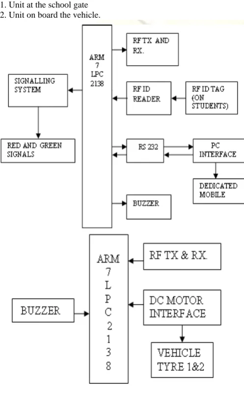
Basically system is divided into two units. 1. Unit at the school gate
2. Unit on board the vehicle.
Fig. 1 Block Diagram of System
SMS that the student has reached the school in time. In case
any parent doesn’t get the SMS in time they can enquire
about the student to the school. The SMS is sent using the
dedicated mobile connected to the school PC using the AT
commands. RF Transceiver unit
:
This unit senses if there
are any vehicles in the close vicinity of the school. If any
car approaches and there is no student at the gate then the
ARM turns the signal to yellow indicating passing vehicle
to slow down. If this unit senses a vehicle and also there is
a student at the gate of the school ready to cross the road
the ARM will immediately turn the signal to RED
indicating to the vehicle to STOP. Also an RF indication is
given to the passing vehicle about the status of the signal.
2. Unit on board the vehicle: This unit also has an RF
Transceiver which sends an indication to the unit of the
school informing about its presence. After this the Unit at
the gate will send the indication about the status of the
signal via the RF module which is received by the
incoming vehicle. If the signal is RED then ARM will stop
the vehicle using the DC motor speed control technique. If
the signal is yellow then the ARM will reduce the speed to
the safe limit automatically. After the student has passed
the Vehicle can go on its way.
VI.
SYSTEM COMPONENTS
ARM7: The LPC2131/32/34/36/38 microcontrollers are
based on a 16/32-bit ARM7TDMI-S CPU with real-time
emulation and embedded trace support, that combine the
microcontroller with 32 kB, 64 kB, 128 kB, 256 kB and
512 kB of embedded high-speed flash memory. A128-bit
wide memory interface and a unique accelerator
architecture enable 32-bit code execution at maximum
clock rate. For critical code size applications, the
alternative 16-bit Thumb mode reduces code by more than
30 % with minimal performance penalty. It is selected for
the following reasons:
1. Two serial ports available
2. Cheap, easily available
3. Plenty guidance available
4. High level of computing possible.
TRANSMISSION MODULE XBEE protocol is used for
wireless communication in between the ARM and the PC.
30 mtrs range, 2.4 GHz frequency XBee. Module is
engineered to meet ZigBee/IEEE 802.15.4 standards and
support the unique needs of low-cost, low-power wireless
sensor networks. The modules require minimal power and
provide reliable delivery of critical data between devices.
The modules operate within the ISM 2.4 GHz frequency
band and are pin-for-pin compatible with each other. RFID
Tag The basic feature of an RFID system is the automatic
identification of items. In its simplest form, such
identification can be binary, e.g., paid or not paid, useful
for alerting. Features 1. Frequency Band - HF 2. Common
Frequency - 13.56 MHz. 3. Coupling - Inductive 4.
Communication Range - 10 to 70 cm. 5. Data Rate - Low 6.
Maturity - Established 7. Reader Cost – Medium
VII.
ADVANTAGES OF SYSTEM
The system is easy to understand.
Avoids the collision of vehicle by controlling the
speed.
Identification of student is easy as RFID tag is
provided to each student.
Easy to set up the system.
Keeps the record of student’s entrance or leaving
time from school.
VIII.
PARFORMANCE ANALYSIS
A. Analysis of Zigbee Transmitter and Receiver for
Different Distances
TABLE I
ANALYSIS OF ZIGBEE TRANSMITTER AND RECEIVER
Sr.
No.
Distance
in Meter
Zigbee Analysis for receiver
1 5-10
The Zigbee receiver receives data
from transmitter successfully.
2 11-21
The Zigbee receiver receives data
from transmitter successfully.
3 22-25
The Zigbee receiver receives data
sometimes.
4 25-30
No data received by Zigbee
receiver from the transmitter
B. Performance of Ultrasonic
sensor TABLE IIANALYSIS OF ULTRASONIC SENSOR FOR STOPPING DISTANCE.
Sr
No.
Fixed
Distance
(in cm)
A
Measured
Stopping
Distance (in
cm) B
Stopped
Distance(in cm)
A-B
1 40 29.72
10.28
2 40 30.68
9.32
3 40 28.44
11.56
4 40 30.24
9.76
5 40 28.89
11.11
Avg. 40
29.61
10.40
C. Analysis for vehicle stopping time
TABLE III
ANALYSIS OF VEHICLE STOPPING TIME FOR THE RECEPTION
OF SIGNAL
Sr No.
Measured Stopping
Time
(in sec)
Average Stopping
Time
(in sec)
1 8.88
8.99
2 9.48
D. Analysis of Vehicle Stopping Distance for the
Reception of Signal
TABLE IV
ANALYSIS OF VEHICLE STOPPING DISTANCE
Sr No.
Measured Stopping
Distance (in cm)
Average
Distance
(in cm)
1 50
49.6
2 48
3 51
4 48.5
5 50.5
IX.
RESULTS
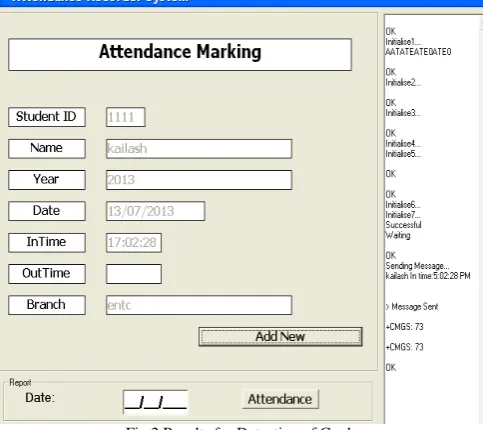
A.
Results for Detection of Card
A RFID Card (tag) which is provided to the student is
read by the reader and card was as detected as buzzer beeps.
So, the information like student’s ID, Name, Year, Branch
read by the card with In time during entrance in school
premises. The results for in time are as shown in following
GUI.
Fig 2 Results for Detection of Card
B.
Attendace Report Generation
To generate the attendance, date of that day is
entered in report window. The GUI for attendance report
generation is as shown.
Fig.3 GUI Result for Generating Attendance Report
Once the date entered in report window,
attendance is generated in Excel sheet. The GUI window
for attendance report generated is as shown.
Fig. 4 GUI Result for Attendance Report
X.
FUTURE SCOPE
Though, the system is well designed still it has limitation
of distance or area coverage. This problem can be solved
using the module of zigbee. For wireless transmission
zigbee is the best solution that can replace existing RF
Transceiver. In addition to this, signal indication i.e. RED
& YELLOW signals may be replace wirelessly instead of
wired.
XI.
APPLICATION
Normally, this type of system is useful in case of
emergency areas where traffic is main concern & little
carelessness may cause accident & death may occur.
Specially, this is useful in following applications.
1. At school gates
2. In hospital premises.
3. In mall premises.
XII.
CONCLUSION
REFERENCES
[1] B. Ulmer. 'VITA - An Autonomous Road Vehicle (ARV) for
Collision Avoidance in Traffic'. In "Proc. of Int. Symp. on Intelligent Vehicles", Detroit June 92.
[2] Hyangjin Lee, Jeeyeon Kim, “Privacy threats and issues in mobile
RFID ” Korea Information Security Agency.
[3] Y. Bar-Shalom, X. Rong Li, T. Kirubarajan, Estimation with
Applications to Tracking and Navigation. Wiley, 2001.
[4] F. Thomanek. et al.“Multiple Object Recognition and Scene
Interpretation forAutonomous Road Vehicle Guidance”.
[5] John Scourias, “Overview of the Global System for Mobile
Communications”,May 19,1995.
[6] Marc Langheinrich, “A Survey of RFID Privacy Approaches”.
[7] Bernhard Riedl,Gernot Glouch,”A Comparative Literature Review
on RFID security and Privacy”.
[8] Kailash V. Karad, Girish A. Kulkarni“Gsm & Rfid Based Tx & Rx