INSTRUCTION MANUAL
144MHz FM TRANSCEIVER
TH-K2AT
TH-K2E
TH-K2ET
430MHz FM TRANSCEIVER
TH-K4AT
TH-K4E
N
OTICETOTHEU
SEROne or more of the following statements may be applicable for this equipment.
FCC WARNING
This equipment generates or uses radio frequency energy. Changes or modifications to this equipment may cause harmful interference unless the modifications are expressly approved in the instruction manual. The user could lose the authority to operate this equipment if an unauthorized change or modification is made.
INFORMATION TO THE DIGITAL DEVICE USER REQUIRED BY THE FCC
This equipment has been tested and found to comply with the limits for a Class B digital device, pursuant to Part 15 of the FCC Rules. These limits are designed to provide reasonable protection against harmful interference in a residential installation.
This equipment generates, uses and can generate radio frequency energy and, if not installed and used in accordance with the instructions, may cause harmful interference to radio communications. However, there is no guarantee that the
interference will not occur in a particular installation. If this equipment does cause harmful interference to radio or television reception, which can be determined by turning the equipment off and on, the user is encouraged to try to correct the interference by one or more of the following measures:
• Reorient or relocate the receiving antenna.
• Increase the separation between the equipment and receiver.
• Connect the equipment to an outlet on a circuit different from that to which the receiver is connected.
M
ODELSC
OVEREDBYTHISM
ANUALThe models listed below are covered by this manual. TH-K2AT, TH-K2E, TH-K2ET
TH-K4AT, TH-K4E
M
ARKETC
ODES Kn: The Americas En: Europe Mn: General(Where n represents a variation number.)
The market code is printed on the bar-code label of the carton box.
P
RECAUTIONSPlease observe the following precautions to prevent fire, personal injury, or transceiver damage:
• Do not transmit with high output power for extended periods. The transceiver may overheat.
• Do not modify this transceiver unless instructed by this manual or by KENWOOD documentation. • When using a regulated power supply, connect the
specified DC cable (option) to the DC IN jack on the transceiver. The supply voltage must be between 12 V and 16 V to prevent damaging the transceiver. • When connecting the transceiver to a cigarette
lighter socket in a vehicle, use the specified cigarette lighter cable (option).
• Do not expose the transceiver to long periods of direct sunlight nor place it close to heating appliances.
• Do not place the transceiver in excessively dusty, humid, or wet areas, nor on unstable surfaces. • If an abnormal odor or smoke is detected coming
NOTICETOTHE USER
MODELS COVEREDBYTHIS MANUAL
MARKET CODES
PRECAUTIONS
CONTENTS ... i
THANK YOU... vi
FEATURES... vi
SUPPLIED ACCESSORIES... vii
WRITING CONVENTIONS FOLLOWED... x
PREPARATION ... 1
INSTALLINGTHE PB-43N NI-MH BATTERY PACK... 1
INSTALLING ALKALINE BATTERIES... 2
INSTALLINGTHE ANTENNA... 4
ATTACHINGTHE HAND STRAP (OTHERTHAN TH-K2AT K/ K2) ... 4
INSTALLINGTHE BELT CLIP... 5
CHARGINGTHE PB-43N NI-MH BATTERY PACK (OTHERTHAN TH-K2AT K2/ M2, TH-K4AT M2) ... 6
CONNECTINGTOA CIGARETTE LIGHTER SOCKET... 8
CONNECTINGTOA REGULATED POWER SUPPLY... 9
YOUR FIRST QSO ... 10
FIRST QSO ... 10
GETTING ACQUAINTED ... 12
KEYSAND CONTROLS... 12
DISPLAY... 14
BASIC OPERATION... 17
Switching the Power ON/OFF ... 17
Adjusting the Volume ... 17
Adjusting the Squelch ... 18
Transmitting ... 19
Selecting an Output Power ... 19
Selecting a Frequency ... 20
VFO Mode ... 20
MHz Mode ... 20
Direct Frequency Entry (TH-K2AT/ET/K4AT only) ... 21
MENU SETUP ... 24
WHATISA MENU? ... 24
MENU ACCESS... 24
MENU FUNCTION LIST ... 26
ALPHABETICAL FUNCTION LIST... 29
OPERATING THROUGH REPEATERS ... 31
OFFSET PROGRAMMING FLOW... 32
Programming an Offset ... 32
Selecting an Offset Direction ... 32
Selecting an Offset Frequency ... 33
Activating the Tone Function ... 34
Selecting a Tone Frequency ... 35
AUTOMATIC REPEATER OFFSET (TH-K2AT/ E/ ET ONLY) ... 37
REVERSE FUNCTION... 38
AUTOMATIC SIMPLEX CHECK (ASC) ... 38
TONE FREQ. ID SCAN... 39
MEMORY CHANNELS ... 41
NUMBEROF MEMORY CHANNELS... 41
SIMPLEX & REPEATEROR ODD-SPLIT MEMORY CHANNEL? ... 42
Storing Simplex Frequencies or Standard Repeater Frequencies ... 44
Storing Odd-Split Repeater Frequencies ... 45
Recalling a Memory Channel ... 46
Using the Tuning Control ... 46
Using a Numeric Keypad (TH-K2AT/ ET/ K4AT only) ... 46
CLEARINGA MEMORY CHANNEL... 47
NAMINGA MEMORY CHANNEL... 48
MEMORY CHANNEL TRANSFER... 50
Memory a VFO Transfer ... 50
Channel a Channel Transfer ... 50
CALL CHANNEL... 53
Recalling the Call Channel ... 53
Reprogramming the Call Channel ... 54
WEATHER ALERT (TH-K2AT K/ K2 ONLY) ... 55
Enabling a Weather Alert ... 56
CHANNEL DISPLAY... 57
SCAN ... 59
NORMAL SCAN... 60
Band Scan ... 60
Program Scan ... 61
Storing a Program Scan Frequency Range ... 61
Performing Program Scan ... 62
MEMORY SCAN... 63
All-Channel Scan ... 63
CALL SCAN... 64
PRIORITY SCAN... 65
Programming Priority Channels ... 65
Using Priority Scan ... 65
MEMORY CHANNEL LOCKOUT... 67
SCAN RESUME METHOD... 68
SELECTIVE CALL ... 69
CTCSS AND DCS ... 69
CTCSS ... 69
Using CTCSS ... 69
Selecting a CTCSS Frequency ... 70
CTCSS Freq. ID Scan ... 72
DCS ... 73
Using DCS ... 73
Selecting a DCS Code ... 74
DCS Code ID Scan ... 75
DTMF FUNCTIONS ... 76
MANUAL DIALING (TH-K2AT/ ET/ K4AT ONLY) ... 76
DTMF TX Hold (TH-K2AT/ ET/ K4AT only) ... 77
AUTOMATIC DIALER... 77
Storing a DTMF Number in Memory ... 77
Transmitting a Stored DTMF Number ... 79
Adjusting the DTMF Tone Transmission Speed ... 80
Adjusting the Pause Duration ... 80
OPERATOR CONVENIENCES ... 82
APO (AUTO POWER OFF) ... 82
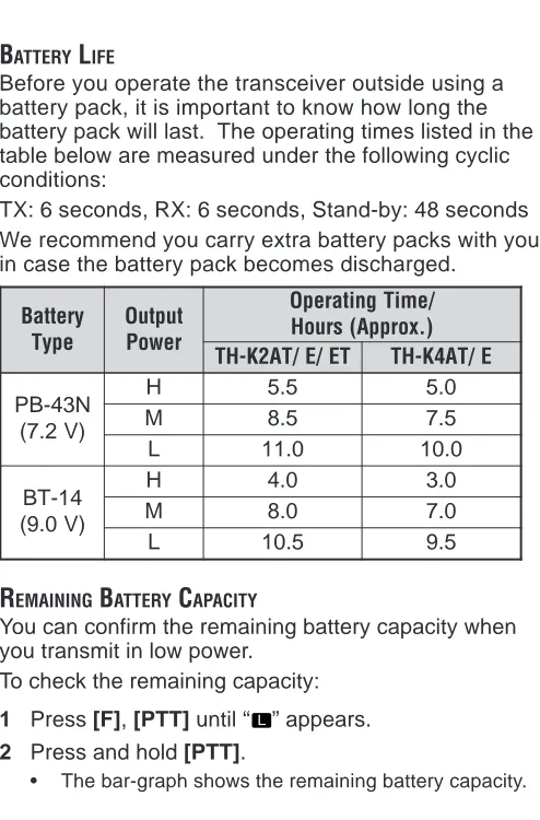
BATTERY LIFE... 83
REMAINING BATTERY CAPACITY... 83
BATTERY SAVER ... 84
BEAT SHIFT... 85
BEEP FUNCTION... 85
BUSY CHANNEL LOCKOUT... 86
FREQUENCY STEP SIZE... 86
LAMP... 88
LOCK FUNCTION... 88
Tuning Control Unlock ... 89
MICROPHONE PF KEYS (OPTIONAL) ... 89
MONITOR... 91
NARROW BAND FM OPERATION... 91
POWER-ON MESSAGE... 92
PROGRAMMABLE VFO ... 93
TIME-OUT TIMER... 94
TX INHIBIT... 95
TX POWER... 95
VOX (VOICE-OPERATED TRANSMISSION) ... 96
VOX Gain ... 97
VOX Delay Time ... 99
VOX on Busy ... 100
OPTIONAL ACCESSORIES ... 101
INTERFACING TO PERIPHERALS ... 104
SP/MIC JACK... 104
SP/MIC ... 104
PC ... 105
Using the PG-4Y PC Interface Cable ... 106
Using the MCP-1A Software ... 107
TROUBLESHOOTING ... 108
GENERAL INFORMATION... 108
Service ... 108
Service Note ... 109
Cleaning ... 110
MICROPROCESSOR RESET... 111
Initial Settings ... 111
Full Reset ... 111
VFO Reset ... 111
Performing Reset ... 112
Full reset ... 112
VFO reset ... 113
Reset using the Menu ... 114
OPERATION NOTICES... 115
Operating Voltage ... 115
Receiving Signals in Cities ... 115
Transmission ... 116
Internal Beats ... 116
TROUBLESHOOTING... 117
INTERNAL BEATS FREQUENCYLIST... 121
SPECIFICATIONS ... 122
T
HANKY
OUThank you for choosing this KENWOOD TH-K2AT/ E/ ET, TH-K4AT/ E transceiver. It has been developed by a team of engineers determined to continue the tradition of excellence and innovation in KENWOOD
transceivers.
Don’t let the size fool you! This small FM portable transceiver features a 5-watt transmitter and various selective calls without installing options. As you learn how to use this transceiver, you will also find that KENWOOD is pursuing “user friendliness”. For example, each time you change the Menu No. in Menu Mode, you will see a text message on the display that lets you know what you are configuring.
Though user friendly, this transceiver is technically sophisticated and some features may be new to you. Consider this manual to be a personal tutorial from the designers. Allow the manual to guide you through the learning process now, then act as a reference in the coming years.
F
EATURES• Compact design
• Aluminum die-cast chassis
• High output power (up to 5 W operation)
• 100 memory channels or 50 channels with names • Long operation period with a Ni-MH battery pack • Menu allows for easy control and selecting of various
functions.
• Optional PC software is available to manage the memory channel contents.
S
UPPLIEDA
CCESSORIESAfter carefully unpacking the transceiver, identify the items listed in the table below. We recommend you keep the box and packings for the shipping.
y r o s s e c c
A PartNumber
y t i t n a u Q T A 2 K -H T
K K2 M M2
k o o h t l e B ) s w e r c s / w
( J29-0709-XX 1 1 1 1
a n n e t n
A T90-1018-XX 1 1 1 1
p a r t
S J69-0342-XX – – 1 1
e s a c y r e t t a
B A02-3817-XX – 1 – 1
y r e t t a b H M -i
N W09-0991-XX 1 – 1 –
r e g r a h
C W08-0959-XX – – 1 –
X X -0 6 9 0 -8 0
W 1 – – –
n o i t c u r t s n I l a u n a M
E B62-1696-XX 1 1 1 1 S B62-1697-XX 1 1 – – G B62-1699-XX – – – – C B62-1695-XX – – – 1 I B62-1702-XX – – – – F B62-1757-XX – – – – D B62-1758-XX – – – – d r a c y t n a r r a
y r o s s e c c
A PartNumber
y t i t n a u Q E 2 K -H
T TH-K2ET
E E3
k o o h t l e B ) s w e r c s / w
( J29-0709-XX 1 1
a n n e t n
A T90-1018-XX 1 1
p a r t
S J69-0342-XX 1 1
e s a c y r e t t a
B A02-3817-XX – –
y r e t t a b H M -i
N W09-0991-XX 1 1
r e g r a h
C W08-0959-XX 1 1
X X -0 6 9 0 -8 0
W – –
n o i t c u r t s n I l a u n a M
E B62-1696-XX 1 1 S B62-1697-XX 1 1 G B62-1699-XX 1 1 C B62-1695-XX – – I B62-1702-XX 1 1 F B62-1757-XX 1 1 D B62-1758-XX 1 1 d r a c y t n a r r a
y r o s s e c c
A PartNumber
y t i t n a u Q T A 4 K -H
T TH-K4E
2
M E3
k o o h t l e B ) s w e r c s / w
( J29-0709-XX 1 1
a n n e t n
A T90-1019-XX 1 1
p a r t
S J69-0342-XX 1 1
e s a c y r e t t a
B A02-3817-XX 1 –
y r e t t a b H M -i
N W09-0991-XX – 1
r e g r a h
C W08-0959-XX – 1
X X -0 6 9 0 -8 0
W – –
n o i t c u r t s n I l a u n a M
E B62-1696-XX 1 1 S B62-1697-XX – 1 G B62-1699-XX – 1 C B62-1695-XX 1 – I B62-1702-XX – 1 F B62-1757-XX – 1 D B62-1758-XX – 1 d r a c y t n a r r a
W
RITINGC
ONVENTIONSF
OLLOWEDThe writing conventions described below have been followed to simplify instructions and avoid unnecessary repetition. n o i t c u r t s n
I WhattoDo
s s e r
P [KEY]. PressandreleaseKEY. s s e r P ] 1 Y E K
[ ,[KEY2].
s s e r
P KEY1momentarliy,release 1
Y E
K ,thenpressKEY2. s s e r P ] Y E K
[ (1s).
d l o h d n a s s e r
P KEYdownfora . d n o c e s s s e r P ] 2 Y E K [ + ] 1 Y E K [ . d l o h d n a s s e r
P KEY1down,then s
s e r
p KEY2. Iftherearemore d l o h d n a s s e r p , s y e k o w t n a h t e h t li t n u n r u t n i y e k h c a e n w o d . d e s s e r p n e e b s a h y e k l a n i f s s e r P ] [ + ] Y E K [ . s s e r p , F F O r e v i e c s n a r t e h t h t i W d l o h d n
a KEY,thenswitchON g n i s s e r p y b r e w o p r e v i e c s n a r t e h t ]
[ (POWER).
Since the amateur radio bands are slightly different from country to country, the following meter band descriptions are used in this manual.
PREPARATION
INSTALLING THE PB-43N Ni-MH BATTERY PACK
Note: Because the battery pack is provided uncharged, you must
charge the battery pack before using it with the transceiver. To charge the battery pack, refer to “CHARGINGTHE PB-43N Ni-MH
BATTERY PACK (Other than TH-K2AT K2/ M2, TH-K4AT M2)” {page 6}.
1 Unlock (open) the safety catch located at the bottom of the battery pack.
2 Match the guides of the battery pack with the corresponding grooves on the upper rear of the transceiver, then firmly press the battery pack to lock it in place.
3 Flip the safety catch into place to prevent
4 To remove the battery pack, lift the safety catch, then press the release latch to unlock the battery pack. Lift the battery pack away from the transceiver.
INSTALLING ALKALINE BATTERIES
2 Insert (or remove) six AA (LR6) Alkaline batteries. • Be sure to match the battery polarities with those
marked in the bottom of the battery case.
3 Align the two tabs at the bottom of battery case, then close the cover until the locking tabs on top click. 4 To install the battery case onto (or remove it from)
the transceiver, follow steps 1 to 3 of “INSTALLINGTHE PB-43N Ni-MH BATTERY PACK” {page 1}.
Note:
◆ Do not use Manganese batteries or Ni-Cd batteries in place of Alkaline batteries.
◆ Always replace all batteries at the same time. Mixing old and new batteries or mixing types (such as Alkaline with zinc carbon) will reduce overall performance and could cause leakage or rupture. ◆ Remove all batteries from the case when it is not expected to be
in use for several months.
◆ The voltage of new Alkaline batteries varies slightly, depending on the manufacturer. Thus, the high battery power indicator may not appear even though new Alkaline batteries are installed {page 83}.
INSTALLING THE ANTENNA
Hold the supplied antenna by its base, then screw it into the connector on the top panel of the transceiver until secure.
ATTACHING THE HAND STRAP (OTHER THAN TH-K2AT K/ K2)
If desired, you can attach the supplied hand strap to the transceiver.INSTALLING THE BELT CLIP
If desired, you can install the supplied belt clip to the transceiver.
1 Loosely insert the two supplied screws into the holes on the back panel of the transceiver.
2 Slide the belt hook into position, under the screws. 3 Tighten the screws until secure.
Note: When the belt hook is not attached to the transceiver, remove
CHARGING THE PB-43N Ni-MH BATTERY PACK
(OTHER THAN TH-K2AT K2/ M2, TH-K4AT M2)
The Ni-MH battery pack can be charged after it has been installed onto the transceiver. (The battery pack is provided uncharged for safety purposes.)1 Confirm that the transceiver power is OFF.
• While charging the battery pack, leave the transceiver power OFF.
2 Insert the charger plug into the DC IN jack of the transceiver.
3 Plug the charger into an AC wall outlet. • Charging starts.
4 It takes approximately 12 hours to charge an empty PB-43N Ni-MH battery pack. After 12 hours, remove the charger plug from the transceiver DC IN jack. 5 Unplug the charger from the AC wall outlet.
Note:
◆ Never leave the battery pack in direct sunlight.
◆ The transceiver becomes warm while charging the battery pack. ◆ While the battery pack is charged, the ambient temperature must
be within 0°C ~ 40°C (32°F ~ 104°F). Otherwise, charging does not start. If the transceiver senses that the temperature is more than 60°C (140° F) during charging, the transceiver stops charging.
◆ Before recharging the battery pack, use the battery pack until the transceiver stops receiving.
◆ Do not plug the charger into the DC IN jack for more than 24 hours.
◆ Unplug the charger as soon as possible after the charging period is over.
◆ After the battery pack is charged, do not unplug and plug the charger into the AC outlet again. Unpluging the charger will reset the charging timer and the battery pack will be charged again. This could result in over-charging.
◆ If the battery pack is recharged repeatedly before the battery pack is not fully used, the memory effect (the battery pack will not allow the charger to recharge the battery to more than a certain voltage level) may occur. In this case, turn the transceiver ON until it stops receiving in order to discharge the battery pack, then recharge the battery pack as normal.
◆ If the battery pack is not used for a long time, the battery pack capacity temporarily decreases. In this case, charge the battery and use the battery pack until the transceiver stops receiving. Repeat this procedure a few times. The battery pack should recover its capacity.
◆ If the charger is plugged into the DC IN jack before the battery pack is attached, turn the transceiver power ON and then OFF again to initiate charging.
◆ Exceeding the specified charge period shortens the useful life of the PB-43N Ni-MH battery pack.
◆ The provided charger is designed to charge only the PB-43N Ni-MH battery pack. Charging other models of battery packs may damage the charger and battery pack.
◆ Do not transmit while charging.
◆ When not in use, store the battery pack in a cool and dry place. ◆ Before charging the PB-43N Ni-MH battery pack, ensure that the
CONNECTING TO A CIGARETTE LIGHTER SOCKET
To connect the transceiver to the cigarette lighter socket in your vehicle, use an optional PG-3J Cigarette Lighter cable.
When the PG-3J is connected to the cigarette lighter plug, the transceiver automatically starts charging the PB-43N Ni-MH battery pack. While you operate the transceiver, it charges the PB-43N Ni-MH battery pack in the background.
To connect with an external 24 V power source via a DC-DC converter, only use the optional PG-3J Cigarette Lighter cable. Using the PG-2W DC cable in this situation may cause a fire.
PG-2W 2 4 V
1 2 V
2 4 V PG-3J
1 2 V 1 2 V
2 4 V PG-3J
Note:
◆ Do not use the PG-2W to connect a vehicle battery (12 V) directly. Extensive voltage could result in damaging the transceiver.
◆ If the input voltage exceeds approximately 16.5 V, warning beeps sound and “DC ERR” appears.
DC-DC Converter Socket
CONNECTING TO A REGULATED POWER SUPPLY
To connect the transceiver to an appropriate regulated DC power supply, use an optional PG-2W DC cable. 1 Confirm that the power of both the transceiver and
the DC power supply is OFF.
2 Connect the optional PG-2W DC cable to the DC power supply; the red lead to the positive (+) terminal, and the black lead to the negative (–) terminal.
3 Connect the barrel plug on the DC cable to the DC IN jack of the transceiver.
While a DC power supply is connected with the DC IN jack, the transceiver automatically initiates charging the PB-43N Ni-MH battery pack.
Note:
◆ If the DC power supply voltage is below 12.0 V DC, you may not be able to charge the PB-43N Ni-MH battery pack.
◆ The supply voltage must be between 12.0 V and 16.0 V to prevent damaging the transceiver. If the input voltage exceeds approximately 16.5 V, warning beeps sound and “DC ERR” appears. Remove the DC IN jack plug immediately.
◆ If the DC power supply voltage is above 14.5 V DC and “ ” (High Power) is selected, the “ ” icon blinks and the output power is gradually reduced to “ ” level (Medium Power) {page 95}.
YOUR FIRST QSO
F
IRSTQSO
Are you ready to give your transceiver a quick try? Reading this chapter should get your voice on the air right away. The instructions below are intended only for a quick guide. If you encounter problems or there is something you would like to know more, read the detailed explanations given later in this manual.
• A high pitched double beep sounds and a Power-ON message appears momentarily. The various indicators and the current operating frequency appear on the LCD. • The transceiver stores the current parameters when it
is turned OFF and automatically recalls these
parameters the next time you turn the transceiver ON. 2 Turn the VOL control clockwise, to the 11 o’clock
position.
3 Turn the Tuning control to select a reception frequency.
VOL ENC.
• You may further turn the VOL control to adjust the volume level of the signal.
4 To transmit, hold the transceiver approximately 5 cm (2 inches) from your mouth.
5 Press and hold [PTT], then speak in your normal tone of voice.
6 Release [PTT] to receive.
GETTING ACQUAINTED
K
EYSANDC
ONTROLSTuning control
TH-K2AT/ ET/ K4AT
LED
(TX:Red RX:Green)
Display (LCD)
SP/MIC jack
DC IN jack
MENU key MONI/SQL key LAMP key Power Switch
PTT switch
Antenna connector
VOL control
TH-K2E/ K4E
Tuning control
VOL control
LED
(TX:Red RX:Green)
Display (LCD)
DC IN jack
Keypad
MENU key MONI/SQL key LAMP key Power Switch
PTT switch
Antenna connector
o u y t r
q w e !1
!2 !4 !3
i !0
!5 !6
!7 !8
q
Appears when the CTCSS function is activated {page 69}.
w
Appears when the Tone function is activated {page 34}.
e
Appears when the DCS function is activated {page 73}. r
Appears when the repeater shift function is activated {pages 31 ~ 34, 37}.
t
Appears when the Reverse function is activated {page 38}.
y
Appears when the Automatic Simplex Check (ASC) function is activated {page 38}.
u
Appears when a Priority Scan function is activated {page 65}.
i
Displays the frequencies, Menu settings, Memory name and other information.
o
Appears when the Weather Alert function is activated {page 55}.
!0
Appears when narrow FM Mode is selected {page 91}. !1
Displays the Menu No., memory channel number, and status {pages 24, 41}.
!2
Appears when the displayed memory channel has data {page 44}.
!3
Appears when the Lock function is ON {page 88}. !4
Appears when the Memory Channel Lockout function is ON {page 67}.
!5
Appears when the VOX function is ON {page 96}. !6
!7
Appears when the function key is pressed. !8
B
ASICO
PERATIONSwitching the Power ON/OFF
1 Press [ ] (POWER) briefly to switch the transceiver power ON.
• A high pitched double beep sounds and a Power-ON message {page 92} appears briefly, followed by the frequency and other indicators.
2 To switch the transceiver OFF, press [ ] (POWER) again.
• When you turn the transceiver OFF, a low pitched double beep sounds.
• The transceiver stores the current frequency and parameters when it is turned OFF and recalls these parameters the next time you turn the transceiver ON. Adjusting the Volume
Turn the VOL control clockwise to increase the audio output level and counterclockwise to decrease the output level.
VOL ENC.
Adjusting the Squelch
The purpose of Squelch is to mute the speaker when no signals are present. With the squelch level correctly set, you will hear sound only while actually receiving signals. The higher the selected squelch level, the stronger the signals must be to receive.
The appropriate squelch level depends on the ambient RF noise conditions.
1 Press [F], [MONI/SQL].
• The current squelch level appears.
2 Turn the Tuning control to adjust the level.
• Select the level at which the background noise is just eliminated when no signal is present.
• The higher the level, the stronger the signals must be to receive.
• 6 different levels can be set.
(0: Minimum ~ 5: Maximum; 2 is the default value) 3 Press any key other than [LAMP], [MONI/SQL] to
Transmitting
1 To transmit, hold the transceiver approximately 5 cm (2 inches) from your mouth, then press and hold [PTT] and speak into the microphone in your normal tone of voice.
• The LED lights red and the bar-graph meter appears. • If you press [PTT] while you are outside of the
transmission coverage, a high pitched error beep sounds.
2 When you finish speaking, release [PTT].
Note: If you continuously transmit for longer than the time specified
in Menu No. 23 (default is 10 minutes) {page 94}, the internal time-out timer generates a warning beep and the transceiver stops transmitting. In this case, release [PTT] and let the transceiver cool down for a while, then press [PTT] again to resume transmission {page 116}.
■ Selecting an Output Power
Selecting a lower transmission power is the best way to reduce battery consumption, if communication is still reliable. You can configure different power levels for transmission {page 95}.
Selecting a Frequency
■ VFO Mode
This is the basic mode for changing the operating frequency. Turn the Tuning control clockwise to increase the frequency and counterclockwise to decrease the frequency.
■ MHz Mode
If the desired operating frequency is far away from the current frequency, it is quicker to use the MHz Tuning Mode.
To adjust the MHz digit: 1 Press [F].
• The MHz digit blinks.
2 Turn the Tuning control to select the desired MHz value.
3 After selecting the desired MHz value, press [F] to exit the mode and return to normal VFO Mode. 4 Continue adjusting the frequency as necessary,
■ Direct Frequency Entry (TH-K2AT/ ET/ K4AT only) In addition to turning the Tuning control, there is another way to select the frequency. When the desired frequency is far away from the current frequency, you can directly enter a frequency using the numeric keypad.
1 Press [VFO].
• You must be in the VFO Mode to make the direct frequency entry.
2 Press [#].
3 Press the numeric keys ([0] to [9]) to enter your desired frequency. [ ] allows you to complete the MHz digits entry.
• Pressing [#] fills all remaining digits (the digits you did not enter) with 0 and completes the entry. For example, to select 145.000 MHz, press [1], [4], [5] and press [#] to complete the entry.
• If you want to revise the MHz digits only, leaving the kHz digits as they are, press [VFO] in place of [#].
Example 1
To enter 145.750 MHz:
Key in Display
Example 2
To enter 145.000 MHz:
Key in Display
[#] – – – – – –
[1], [4], [5] 1 4 5. – – –
[#] 1 4 5. 0 0 0
Example 3 (Short cut) To enter 145.000 MHz:
Key in Display
1 4 4. 6 2 5
[#] – – – – – –
[5] 5 – –. – – –
[ ] 1 4 5. – – –
[#] 1 4 5. 0 0 0
Example 4
To change 144.650 MHz to 145.650 MHz:
Key in Display
1 4 4. 6 5 0
[#] – – – – – –
[1], [4], [5] 1 4 5. – – –
Example 5 (Short cut)
To change 144.650 MHz to 145.650 MHz:
Key in Display
1 4 4. 6 5 0
[#] – – – – – –
[5] 5 – – – – –
[ ] 1 4 5. – – –
[VFO] 1 4 5. 6 5 0
Example 6
To change 145.200 MHz to 145.750 MHz:
Key in Display
1 4 5. 2 0 0
[#] – – – – – –
[ ] 1 4 5. – – –
[7], [5], [0] 1 4 5. 7 5 0 Note:
◆ If the entered frequency does not match the current frequency step size, the frequency is automatically rounded down to the next available frequency.
◆ When the desired frequency cannot be entered exactly, confirm the frequency step size {page 86}.
MENU SETUP
W
HATISAM
ENU?
Many functions on this transceiver are selected or configured via a software-controlled Menu rather than through the physical controls of the transceiver. Once you become familiar with the Menu system, you will appreciate its versatility. You can customize the various timings, settings, and programming functions on this transceiver to meet your needs without using many controls and switches.
M
ENUA
CCESS1 Press [MENU].
• A brief explanation of the Menu, and the setting and Menu No. appear on the display.
2 Turn the Tuning control to select your desired Menu. • As you change the Menu No., a brief explanation of
each Menu appears along with its current parameter. Menu No. Parameter
3 Press [MENU] to configure the parameter of the currently selected Menu No.
4 Turn the Tuning control to select your desired parameter.
5 Press [MENU] to store the new setting. Otherwise, press any key other than [LAMP], [MONI/SQL] or [ ] (POWER) to cancel.
Note:
◆ The [LAMP] and [MONI/SQL] keys can be operated while configuring the Menu.
M
ENUF
UNCTIONL
IST e h t n O y a l p s i D u n e M . oN Function Selections Default . f e R e g a P P T
S 1 1 Frequencystep
e z i s / 0 1 / 5 2 . 6 / 5 / 5 2 / 0 2 / 5 1 / 5 . 2 1 z H k 0 0 1 / 0 5 / 0 3 / 5 . 2 1 / 5 5 2 86
S C D . T C .
T 2 TDoCnSe/sCelTeCctSioSn/ OCTFCF/STSO/NDEC/S OFF 34,
3 7 , 9 6
T 3 Tonefrequency 67.0~254.1Hz 88.5 35
T
C 4 CTCSS y c n e u q e r
f 67.0~254.1Hz 88.5 70 S
C
D 5 DCScode 023~754 023 74
T F
S 6 Shiftdirection OFF/+/–/–7.6 OFF 32
O F V .
P 7 Programmable O F V z H M 4 7 1 ~ 6 3 1 ) T A 2 K -H T ( z H M 6 4 1 ~ 4 4 1 ) T E / E 2 K -H T ( z H M 0 7 4 ~ 0 0 4 ) T A 4 K -H T ( z H M 0 4 4 ~ 0 3 4 ) E 4 K -H T ( 3 9 T E S F F
O 1 8 Repeateroffset
y c n e u q e r f 0 5 9 . 9 6 ~ 0 0 0 . 0 z H M / 0 0 6 . 0 / 0 0 6 . 1 0 0 0 . 5 3 3 O R
A 2 9 Automatic
t e s f f O r e t a e p e
R ON/OFF ON 37
I R
P 10 Priorityscan ON/OFF OFF 66
N A C
S 11 Scanresume d o h t e
m TO/CO/SE TO 68
T U O .
L 12 lMocekmoourtychannelON/OFF OFF 67
H C .
M 13 Memorychannel y t i c a p a
e h t n O y a l p s i D u n e M . o
N Function Selections Default . f e R e g a P E M A N .
M 14 Memoryname 6characters – 48
F D
M 15
/ e m a n y r o m e M y c n e u q e r F y a l p s i d Q R F / N
M MN 49
V A
S 16 Batterysaver
/ 4 . 0 / 2 . 0 / F F O / 0 . 1 / 8 . 0 / 6 . 0 0 . 5 / 0 . 4 / 0 . 3 / 0 . 2 0 . 1 84
O P
A 17 Automatic F F O -r e w o P / 0 9 / 0 6 / 0 3 / F F O . n i m 0 8 1 / 0 2
1 30 82
K
C 1 18 CALLkey CALL/1750 CALL/
0 5 7
1 36,64
D L
H 19 1750Hztone d l o h X
T ON/OFF OFF 36 X
O
V 20 VOXfunction OFF/1~9 OFF 96
B X
V 21 VOXonbusy ON/OFF OFF 100
D
V 22 VOXdelay
/ 0 5 7 / 0 0 5 / 0 5 2 / 0 0 5 1 / 0 0 0 1 s m 0 0 0 3 / 0 0 0 2 0 0 5 99
T O
T 23 Time-outTimer 3/5/10minutes 10 94
L C
B 24 Busychannel t u o k c o
l ON/OFF OFF 86 I
X
T 25 TXinhibit ON/OFF OFF 95
G S M . N O .
P 26 Power-ON e g a s s e
m 6characters – 92 P
B 27 Beep ON/OFF ON 85
S
B 28 BeatShift ON/OFF OFF 85
N M
F 29 NarrowFM ON/OFF OFF 91
C N
e h t n O
y a l p s i D
u n e M
. o
N Function Selections Default . f e R
e g a P
C
P 31 PCcontrol ON/OFF OFF 107
R M . F M T
D 32 Automaticdialer Upto16digits – 77
D P
S 33 DTMFTXspeedFA/SL FA 80
H . T
D 3 34 DTMFTXhold ON/OFF OFF 77
A
P 35 DpeTrMioFdpause
/ 0 0 5 / 0 5 2 / 0 0 1
/ 0 0 0 1 / 0 5 7
s m 0 0 0 2 / 0 0 5 1
0 0
5 80
L . T
D 36 DTMFkeylock ON/OFF OFF 81
A X
W 4 37 WeatherAlert ON/OFF OFF 56
T E S E
R 99 Resetselection VFO/FULL VFO 111
1 Default settings vary according to the transceiver model you are
using. See the reference page to determine which default setting is available for your transceiver.
2 Only available for TH-K2AT K/ K2 and TH-K2E/ ET
3 Only available for TH-K2AT/ ET and TH-K4AT
e h t n O y a l p s i D u n e M . o
N Selections Default . f e R e g a P O P
A 17 OFF/30/60/90/120/180min. 30 82 O
R
A 2 9 ON/OFF ON 37
L C
B 24 ON/OFF OFF 86
P
B 27 ON/OFF ON 85
S
B 28 ON/OFF OFF 85
K
C 1 18 CALL/1750 CALL/
0 5 7 1 , 6 3 4 6 T
C 4 67.0~254.1Hz 88.5 70 S
C
D 5 023~754 023 74
R M . F M T
D 32 Upto16digits – 77 H
. T
D 3 34 ON/OFF OFF 77
L . T
D 36 ON/OFF OFF 81
C N
E 30 ON/OFF OFF 89
N M
F 29 ON/OFF OFF 91
D L
H 19 ON/OFF OFF 36
T U O .
L 12 ON/OFF OFF 67
H C .
M 13 50/100 50 41
F D
M 15 MN/FRQ MN 49
E M A N .
M 14 6characters – 48
T E S F F
O 1 8 0.000~69.950MHzinstepsof
z H k 0 5 / 0 0 6 . 0 / 0 0 6 . 1 0 0 0 . 5 3 3 A
P 35 2100000/2m5s0/500/750/1000/1500/ 500 80
C
P 31 ON/OFF OFF 107
G S M . N O .
P 26 6characters – 92
e h t n O y a l p s i D u n e M . o
N Selections Default . f e R e g a P I R
P 10 ON/OFF OFF 66
O F V . P 7 ) T A 2 K -H T ( z H M 4 7 1 ~ 6 3 1 ) T E / E 2 K -H T ( z H M 6 4 1 ~ 4 4 1 ) T A 4 K -H T ( z H M 0 7 4 ~ 0 0 4 ) E 4 K -H T ( z H M 0 4 4 ~ 0 3 4 3 9 T E S E
R 99 VFO/FULL VFO 111
V A
S 16 OFF/0.2/0.4/0.6/0.8/1.0/2.0/ 0 . 5 / 0 . 4 / 0 .
3 1.0 84
N A C
S 11 TO/CO/SE TO 68
T F
S 1 6 OFF/+/–/–7.6 OFF 32
D P
S 33 FA/SL FA 80
P T
S 1 1 5/6.25/10/12.5/15/20/25/30/
z H k 0 0 1 / 0 5 / 5 . 2 1 / 5 5 2 86 T 3 67.0~254.1Hz 88.5 35
S C D . T C .
T 2 OFF/TONE/CTCSS/DCS OFF 693,47,3
T O
T 23 3/5/10minutes 10 94 I
X
T 25 ON/OFF OFF 95
D
V 22 2205000//50300/0075m0/s1000/1500/ 500 99
X O
V 20 OFF/1~9 OFF 96
B X
V 21 ON/OFF OFF 100
A X
W 4 37 ON/OFF OFF 56
1 Default settings vary according to the transceiver model you are
using. See the reference page to determine which default setting is available for your transceiver.
2 Only available for TH-K2AT K/ K2 and TH-K2E/ ET
3 Only available for TH-K2AT/ ET and TH-K4AT
OPERATING THROUGH REPEATERS
Repeaters, which are often installed and maintained by radio clubs, are usually located on mountain tops or other elevated locations. They generally operate at higher ERP (Effective Radiated Power) than a typical station. This combination of elevation and high ERP allows communications over much greater distances than communicating without using repeaters.
Most repeaters use a receive and transmit frequency pair with a standard or non-standard offset (odd-split). In addition, some repeaters must receive a tone from the transceiver to be accessed. For details, consult your local repeater reference.
TX: 144.725 MHz TX tone: 88.5 Hz
O
FFSETP
ROGRAMMINGF
LOWq
w
e
r
t
Select a receive frequency.
Select an offset direction.
Select an offset frequency
(only when programming odd-split repeater frequencies).
Activate the Tone function (if necessary).
Select a tone frequency (if necessary).
If you store all the above data in a memory channel, you will not need to reprogram the parameters every time. Refer to “MEMORY CHANNELS” {page 41}.
Programming an Offset
You must first select an amateur radio repeater downlink frequency as described in “Selecting an Offset
Frequency” {page 33}.
■ Selecting an Offset Direction
1 Press [MENU].
2 Turn the Tuning control to select Menu No. 6 (SFT).
3 Press [MENU].
4 Turn the Tuning control to select “+” or “–”. • To program a –7.6 MHz offset (TH-K4E only),
select “–7.6” instead.
5 Press [MENU] to store the setting or [PTT] to cancel.
• “+” or “–” (or “ ”) appears above the frequency, indicating which offset direction is selected.
If the offset transmission frequency falls outside the allowable range, transmission is inhibited. In this case, adjust the reception frequency so that the transmission frequency is within the band limits.
Note: While using an odd-split memory channel or transmitting,
you cannot change the offset direction.
■ Selecting an Offset Frequency
1 Press [MENU].
2 Turn the Tuning control to select Menu No. 8 (OFFSET).
3 Press [MENU].
4 Turn the Tuning control to select the appropriate offset frequency.
• The selectable range is from 0.000 MHz to 69.950 MHz in steps of 50 kHz.
5 Press [MENU] to store the setting or [PTT] to cancel.
6 Press any key other than [LAMP], [MONI/SQL], and [MENU] to exit Menu Mode.
TH-K4E only: If you have selected “ ” for the offset direction, you cannot change the default (–7.6 MHz) offset frequency.
Note: After changing the offset frequency, the new offset
frequency will also be used by Automatic Repeater Offset.
■ Activating the Tone Function
1 Press [MENU].
3 Press [MENU].
4 Turn the Tuning control to select “TONE”. 5 Press [MENU] to store the setting or [PTT] to
cancel.
6 Press any key other than [LAMP], [MONI/SQL], and [MENU] to exit Menu Mode.
• “T” appears when the Tone function is ON. Note: You cannot use the Tone and CTCSS/ DCS functions at
the same time. Switching the Tone function ON after activating the CTCSS/ DCS deactivates the CTCSS/ DCS function.
TH-K2E/ ET/ K4E only: When you access repeaters that require
a 1750 Hz tone, you do not need to activate the Tone function. Simply press [CALL] without pressing [PTT] switch to transmit a 1750 Hz tone (default setting).
■ Selecting a Tone Frequency
1 Press [MENU].
2 Turn the Tuning control to select Menu No. 3 (T). 3 Press [MENU].
4 Turn the Tuning control to select the desired tone frequency.
5 Press [MENU] to store the setting or [PTT] to cancel.
Available Tone Frequencies
) z H ( y c n e u q e r F e n o T
0 . 7
6 82.5 100.0 123.0 151.4 186.2 225.7 3
. 9
6 85.4 103.5 127.3 156.7 192.8 229.1 9
. 1
7 88.5 107.2 131.8 162.2 203.5 233.6 4
. 4
7 91.5 110.9 136.5 167.9 206.5 241.8 0
. 7
7 94.8 114.8 141.3 173.8 210.7 250.3 7
. 9
7 97.4 118.8 146.2 179.9 218.1 254.1 Note: 42 different tones are available for the transceiver. These
42 tones includes 37 EIA standard tones and 5 non-standard tones.
TH-K2E/ ET/ K4E only:
◆ To transmit a 1750 Hz tone, simply press [CALL] without pressing [PTT] (default setting). Release [CALL] to quit transmitting. You can also make the transceiver remain in the transmit mode for 2 seconds after releasing [CALL]; a 1750 Hz tone is not continuously transmitted. Access Menu No. 19 (HLD) and select “ON”.
◆ If you want to use [CALL] for recalling the Call channel in place of transmitting a 1750 Hz tone, access Menu No. 18 (CK) and select “CALL”.
TH-K2E/ 4E only:
◆ If you press [CALL] while transmitting, 1750 Hz tone will be transmitted.
TH-K2AT/ ET/ K4AT only:
A
UTOMATICR
EPEATERO
FFSET(TH-K2AT/ E/ ET
ONLY)
This function automatically selects an offset direction, according to the frequency on the 2 m band. The transceiver is programmed for offset direction as shown below. To obtain an up-to-date band plan for repeater offset direction, contact your national Amateur Radio association.
TH-K2AT K/ K2 only
+ – –
– S + S S S
144.0 145.5 146.4 147.0 147.6 145.1 146.0 146.6 147.4 148.0 MHz S: Simplex
This complies with the standard ARRL band plan.
TH-K2E/ K2ET only
S S
S: Simplex
–
144.0 145.6 145.8146.0 MHz
Note: Automatic Repeater Offset does not function when the
Reverse function is ON {page 38}. However, pressing [F], [MENU] after Automatic Repeater Offset has selected an offset (split) status, exchanges the receive and transmit frequencies.
1 Press [MENU].
2 Turn the Tuning control to select Menu No. 9 (ARO). 3 Press [MENU].
4 Turn the Tuning control to switch the function “ON” (default) or “OFF”.
R
EVERSEF
UNCTIONThe Reverse function exchanges a separate reception and transmission frequency. So, while using a repeater, you can manually check the strength of a signal that you receive directly from the other station. If the station’s signal is strong, both stations should move to a simplex frequency and free up the repeater.
To swap the transmission and reception frequencies: Press [F], [MENU] to switch the Reverse function ON (or OFF).
• “R” appears when the function is ON.
Note: You can turn the Reverse function ON when you are operating
in Simplex Mode. However, it does not change the Transmission/ Reception frequency.
A
UTOMATICS
IMPLEXC
HECK(ASC)
Press [F], [MENU] (1 s) to switch the function ON (or OFF).
• “ ” appears when the function is ON. • While direct contact is possible, “ ” blinks.
Note:
◆ Pressing [PTT] switch causes the “ ” icon to quit blinking.
◆ ASC can be activated while operating in Simplex mode. However, it does not change the Transmission/ Reception frequencies.
◆ ASC does not function during scan.
◆ ASC does not function while Weather Alert function is activated (TH-K2AT K/ K2 only) {page 55}.
◆ Activating ASC while using Reverse, turns Reverse function OFF.
◆ If you recall a memory channel or the Call Channel that contains a Reverse ON status, ASC is switched OFF.
◆ ASC causes received audio to be momentarily intermitted every 3 seconds.
T
ONEF
REQ. ID S
CANThis function scans through all tone frequencies to identify the incoming tone frequency on a received signal. You can use this function to determine which tone frequency is required by accessing your local repeater.
1 Press [MENU].
3 Press [MENU] (1 s).
• When the transceiver receives a signal, scan starts. The decimal point blinks during scan.
• While the transceiver is receiving a signal during Tone Freq. ID Scan, the signal is emitted from the speaker. • To reverse the scan direction, turn the Tuning control. • To quit the function, press [PTT].
• When the tone frequency is identified, a beep sounds and the identified frequency blinks.
4 Press [MENU] to program the identified frequency in place of the current tone frequency.
• Press any key other than [MENU], [LAMP], and [MONI/SQL] if you do not want to program the identified frequency.
• Turn the Tuning control while the identified frequency is blinking to resume scanning.
Note: Some repeaters do not re-transmit the access tone in the
MEMORY CHANNELS
In memory channels, you can store frequencies and related data that you frequently use so that you do not need to reprogram that data every time. You can quickly recall a programmed channel through simple operation. A total of 100 memory channels (50 when using the Memory Name function) are available for storing frequencies, modes and other operating conditions.
N
UMBEROFM
EMORYC
HANNELSThe transceiver must be configured to either 100 memory channels without using the Memory Name function or 50 memory channels with the Memory Name function (default).
To change the memory channel capacity: 1 Press [MENU].
2 Turn the Tuning control to select Menu No. 13 (M.CH).
3 Press [MENU].
4 Turn the Tuning control to select either “50” (default) or “100”.
5 Press [MENU]. • “SURE ?” appears.
Note:
◆ If you change the memory channel capacity from 100 channels to 50 channels after having stored data in channels 50 to 99, all memory channel data in channels 50 to 99 will be erased. ◆ If you change the memory channel capacity from 50 channels to
100 channels after storing Memory names in those channels, all Memory name data will be erased.
S
IMPLEX& R
EPEATERORO
DD-S
PLITM
EMORYC
HANNEL?
You can use each memory channel as a simplex & repeater channel or an odd-split channel. Store only one frequency to use as a simplex & repeater channel or two separate frequencies to use as an odd-split channel. Select either application for each channel depending on the operations you have in mind. Simplex & repeater channels allow:• Simplex frequency operation
• Repeater operation with a standard offset (if an offset direction is stored)
Odd-split channels allow:
• Repeater operation with a non-standard offset
Note: Not only you can store data in memory channels, but you can
The data listed below can be stored in each memory channel: r e t e m a r a
P Simplex& r e t a e p e
R Odd-Split
y c n e u q e r f n o i t p e c e R s e
Y Yes
y c n e u q e r f n o i s s i m s n a r
T Yes
y c n e u q e r f e n o
T Yes Yes
N O e n o
T Yes Yes
y c n e u q e r f S S C T
C Yes Yes
N O S S C T
C Yes Yes
e d o c S C
D Yes Yes
N O S C
D Yes Yes
n o i t c e r i d t e s f f
O Yes N/A
y c n e u q e r f t e s f f
O Yes N/A
N O e s r e v e
R Yes N/A
e z i s p e t s y c n e u q e r
F Yes Yes
M F d n a b w o r r a
N Yes Yes
t f i h S t a e
B Yes Yes
t u o k c o L l e n n a h C y r o m e
M Yes Yes
e m a N l e n n a h C y r o m e
M Yes Yes
Storing Simplex Frequencies or Standard Repeater Frequencies
1 Press [VFO].
2 Turn the Tuning control to select your desired frequency.
• You can also directly enter a desired frequency using the keypad (TH-K2AT/ ET/ K4AT only) {page 21}. 3 If storing a standard repeater frequency, select the
following data:
• Offset direction {page 32}
• Tone function, if necessary {page 34}
• CTCSS/ DCS function, if necessary {pages 69, 73} If storing a simplex frequency, you may select other related data (CTCSS or DCS settings, etc.).
4 Press [F], [MR].
• A memory channel number appears and blinks. • “ ” appears if the channel contains data.
• Memory channel number L0/U0 ~ L2/U2 {page 61}, Pr (Priority Channel) {page 65} and AL (Weather Alert) {page 55} (TH-K2AT K/ K2 only) are reserved for other functions.
Storing Odd-Split Repeater Frequencies Some repeaters use a pair of reception and
transmission frequencies with a non-standard offset. If you store two separate frequencies in a memory channel, you can operate on those repeaters without programming the offset frequency and direction. 1 Store the desired reception frequency and related
data by following the procedure given for simplex or standard repeater frequencies {page 44}.
2 Turn the Tuning control to select the desired transmission frequency.
3 Press [F], [MR].
4 Turn the Tuning control to select the memory channel you programmed in step 1.
5 Press [PTT]+[MR].
• The transmission frequency is stored in the memory channel.
Note: When you recall an odd-split memory channel, “+” and “–”
appear on the display. To confirm the transmission frequency, press
Recalling a Memory Channel
■ Using the Tuning Control
1 Press [MR] to enter Memory Recall Mode. • The memory channel last used is recalled. 2 Turn the Tuning control to select your desired
memory channel.
• You cannot recall an empty memory channel. • To restore VFO Mode, press [VFO].
■ Using a Numeric Keypad (TH-K2AT/ ET/ K4AT only) You can also recall a memory channel by entering a desired memory channel number with the keypad. 1 Press [MR] to enter Memory Recall Mode. 2 Press [#], then enter the channel number using
2 digits.
• For example, to recall channel 49, press [#], [4], [9].
Note:
◆ You cannot recall an empty memory channel. An error beep sounds.
◆ You cannot recall the Program Scan memory channels (L0/U0 ~ L2/U2), Priority Channel (Pr) and Weather Alert (AL) (TH-K2AT K/ K2 only) using the numeric keypad.
◆ When you recall an odd-split memory channel, “+” and “–” appear on the display. Press [F], [MENU] (Reverse function) {page 38} to display the transmission frequency.
◆ After recalling a memory channel, you may modify data such as Tone or CTCSS. However, these settings are cleared once you select another channel or the VFO Mode. To permanently store the data, overwrite the channel contents {page 44}.
C
LEARINGAM
EMORYC
HANNELTo clear the data from an individual memory channel: 1 Recall the memory channel you want to clear the
data.
2 Press and hold [ ] (POWER) to switch the transceiver OFF.
3 Press [MR]+[ ] (POWER). • A confirmation message appears.
4 Press [MR] to clear the channel data.
• The contents of the memory channel are cleared. • To quit clearing the memory channel, press any key
Note:
◆ Call Channel data cannot be cleared.
◆ You can also clear the Priority Channel, L0/U0 ~ L2/U2 and Weather Alert data.
◆ While the trasceiver is in Channel Display Mode or Lock function is activated, you cannot clear the channel data.
◆ To clear all memory channels contents at once, perform Full Reset {page 111}.
N
AMINGAM
EMORYC
HANNELYou can name memory channels using up to 6 alphanumeric characters. When you recall a named memory channel, its name appears on the display in place of the stored frequency. Names can be call signs, repeater names, cities, names of people, etc. In order to use the Memory Name function, the memory channel capacity must be set to 50 channels. To change the memory channel capacity from 100 to 50, access Menu No. 13 (M.CH) {page 41}.
1 Press [MR] to recall your desired memory channel. 2 Press [MENU] to enter Menu Mode.
3 Turn the Tuning control to select Menu No. 14 (M.NAME).
4 Press [MENU].
• A blinking cursor appears.
• You can enter the following alphanumeric characters: 0 ~ 9, A ~ Z, – (hyphen), / (slash), and a space. • Press [MONI/SQL] to delete the character at the
current cursor position. 6 Press [MENU].
• The cursor moves to the next digit.
7 Repeat steps 5 and 6 to enter up to 6 digits.
• To complete the entry, press [MENU] without selecting a character.
• Press [MONI/SQL] to delete a character.
• Press any key other than [MONI/SQL], [MENU], and [LAMP] to cancel the entry.
After storing a Memory name, the Memory name appears in place of the operating frequency. However, you can still display the operating frequency, if desired. To display the frequency rather than Memory name, access Menu No. 15 (MDF) and select “FRQ”. This menu toggles the display mode between the Memory name (“MN”) and frequency display (“FRQ”).
Note:
◆ You cannot name the Call Channel {page 53}.
◆ You cannot assign a Memory name to a channel that does not contain data.
◆ You can overwrite stored names by repeating steps 1 to 7.
M
EMORYC
HANNELT
RANSFERMemory \ VFO Transfer
After retrieving frequencies and associated data from Memory Recall Mode, you can copy the data to the VFO. This function is useful, for example, when the frequency you want to monitor is near the frequency stored in a memory channel.
1 Press [MR], then turn the Tuning control to recall a desired memory channel.
2 Press [F], [VFO] to copy the memory channel data to the VFO.
Note:
◆ To copy an odd-split channel data {page 45}, turn the Reverse function ON {page 38} before performing the transfer.
◆ You can also transfer the Program Scan memory channels (L0/U0 ~ L2/U2), the Priority Channel (Pr) and Weather Alert (AL) frequency (TH-K2AT K/ K2 only) to the VFO.
Channel \ Channel Transfer
You can copy channel information from one memory channel to another. This function is useful when storing frequencies and associated data that you temporarily change in Memory Recall Mode.
1 Press [MR], then turn the Tuning control to recall a desired memory channel.
3 Select the memory channel where you would like the data copied, using the Tuning control.
4 Press [MR].
The tables below illustrate how data is transferred between memory channels.
9 9 ~ 0 l e n n a h
C a Channel0~99
y c n e u q e r f n o i t p e c e
R a Receptionfrequency y c n e u q e r f n o i s s i m s n a r
T a Transmissionfrequency y c n e u q e r f e n o
T a Tonefrequency n o i t c e r i d t e s f f
O a Offsetdirection y c n e u q e r f S S C T
C a CTCSSfrequency e d o c S C
D a DCScode
S C D / S S C T C / e n o T s u t a t s F F O / N O a S C D / S S C T C / e n o T s u t a t s F F O / N O y c n e u q e r f t e s f f
O a Offsetfrequency N O e s r e v e
R a ReverseON
e z i s p e t s y c n e u q e r
F a Frequencystepsize e m a n l e n n a h c y r o m e
M 1 a Memorychannelname1
9 9 ~ 0 l e n n a h
C a L0/U0~L2/U2,Pr,AL1
y c n e u q e r f n o i t p e c e
R a Receptionfrequency y c n e u q e r f n o i s s i m s n a r
T a Transmissionfrequency y c n e u q e r f e n o
T a Tonefrequency n o i t c e r i d t e s f f
O a Offsetdirection y c n e u q e r f S S C T
C a CTCSSfrequency e d o c S C
D a DCScode
S C D / S S C T C / e n o T s u t a t s F F O / N O a S C D / S S C T C / e n o T s u t a t s F F O / N O y c n e u q e r f t e s f f
O a Offsetfrequency N O e s r e v e
R a ReverseON
e z i s p e t s y c n e u q e r
F a Frequencystepsize e m a n l e n n a h c y r o m e
M 2 a Memorychannelname2
l e n n a h C y r o m e M N O t u o k c o L a l e n n a h C y r o m e M F F O t u o k c o L
1 TH-K2AT K/ K2 only
2 When “50” is selected in Menu No.13 (M.CH).
Note: When transferring an odd-split channel, the Reverse status,
C
ALLC
HANNELThe Call Channel can be recalled instantly no matter what frequency the transceiver is operating on. For instance, you may use the Call Channel as an
emergency channel within your group. In this case, Call Scan {page 64} will be useful.
The default Call Channel frequencies are 144.000 MHz for the 2 m band (all TH-K2 models), and 430.000 MHz (all TH-K4 models) for the 70 cm band.
Note: Unlike memory channels 0 to 99, the Call Channel cannot be
cleared.
Recalling the Call Channel
1 Press [CALL] to recall the Call Channel. • The Call Channel frequency and “C” appear.
Reprogramming the Call Channel
1 Select your desired frequency and related data (Tone, CTCSS, DCS, or offset direction, etc.). • When you program the Call Channel as an odd-split
channel, select a reception frequency first. 2 Press [F], [CALL].
• The selected frequency and related data are stored in the Call Channel.
To also store a separate transmit frequency, continue with the following steps.
3 Select the desired transmission frequency. 4 Press [F].
5 Press [PTT]+[CALL].
• The separate transmission frequency is stored in the Call Channel.
Note:
◆ When you recall an odd-split Call Channel, “+” and “–” appear on the display.
W
EATHERA
LERT(TH-K2AT K/ K2
ONLY)
One of the NOAA Weather Radio channels can be programmed to the AL memory channel of the TH-K2AT. The transceiver can be configured to check the NOAA Weather Alert tone (1050 Hz) and will automatically alert you by recalling and monitoring the Weather Radio frequency when the Weather Alert tone is broadcasted. Programming the Weather Radio Frequency
The transceiver is preprogrammed to 162.550 MHz (WX1). You can store a different frequency to the AL channel to use this function. Refer to the NOAA channel frequency directory for your local Weather Radio frequency before you use the Weather Alert function. The latest Weather Radio information can be obtained from http://www.nws.noaa.gov/nwr/.
1 Press [VFO].
2 Select your local NOAA Weather Radio frequency using the Tuning control or keypad.
3 Press [F], [MR].
4 Turn the Tuning control to select memory channel “AL” (Alert).
5 Press [MR].
• A long beep sounds and the new NOAA Weather Radio frequency is stored to memory channel “AL”.
) z H M ( s e i c n e u q e r F o i d a R r e h t a e W
1 X
W WX2 WX3 WX4 WX5 WX6 WX7 WX8
0 5 5 . 2 6
Note:
◆ When you perform Full Reset {page 111}, the Weather Radio frequency recovers the factory default frequency (162.550 MHz).
◆ When you clear the Weather Radio channel {page 47}, the factory default frequency (162.550 MHz) will not be recovered.
◆ You can also transfer the AL memory channel data to the VFO or another memory channel.
Enabling a Weather Alert
You can monitor the Weather Radio frequency continuously or in the background while receiving on another frequency.
To monitor the Weather Radio frequency continuously: 1 Press [MENU].
2 Turn the Tuning control to select Menu No. 37 (WXA).
3 Press [MENU] and turn the Tuning control to select “ON”.
4 Press [MENU] to store the setting.
• The frequency automatically changes to the Weather Radio frequency.
• “WX” appears on the LCD and the transceiver mutes. • The Tone, CTCSS and DCS functions cannot be
configured to the AL channel.
• When the Weather Alert tone is broadcasted, a morse code “WX” sounds from speaker and the transceiver unmutes.
If you want to monitor another frequency while monitoring the Weather Radio in the background: 1 Perform step 1 ~ 4 above.
2 Press [VFO] or [MR] and turn the Tuning control to select another frequency or memory channel. • “WX” remains on the LCD.
3 When the Weather Alert tone is broadcasted, the transceiver automatically switches to the Weather Radio frequency.
4 To exit the Weather Alert Mode, press [MENU], select Menu No. 37 (WXA), and set it to “OFF”. Note:
◆ The transceiver checks the weather alert tone every 1 second while you are monitoring another frequency or channel.
◆ If the transceiver is transmitting or receiving a signal on another frequency, Weather Alert function temporarily pauses.
C
HANNELD
ISPLAYWhile in this mode, the transceiver displays only memory channel numbers (or Memory names if they have been stored), instead of frequencies.
1 Press [PTT]+[MR]+[ ] (POWER).
• The transceiver displays the memory channel number in place of the operating frequencies.