Dynamic Model and Simulation of Wind
Energy Conversion System based on
Permanent Magnet Synchronous Generator
Molla Biweta1, Dr. Mengesha Mamo2, Dr. H.G.Eckel3
Assistant Professor, Dept. of ECE, Adama Science and Technology University, Adama, Ethiopia1
Associate Professor, Dept. of ECE, AAIoT, Addis Ababa University, Addis Ababa, Ethiopia2
Professor, Dept. of EE, University of Rostock, Rostock, Germany3
ABSTRACT: In modern wind turbines, the energy conversion process uses the basic aerodynamic force of lift to produce a net positive torque on a rotating shaft, resulting first in the production of mechanical power and then its conversion to electricity in a generator. Wind turbines, unlike most other turbines, can produce power only in response to the wind that is available at the time. The output of a wind turbine is thus inherently fluctuating with the wind and can’t be directly dispatched for a purpose. Apart from this, the output depends on individual components like rotor dimension, transmission shaft, gear box and alternator. Since the wind turbine is relatively large, expensive, and Wind Energy Conversion System (WECS) is complex, it is not convenient to do research on actual wind farm. Therefore, WECS model development for steady and dynamic state analysis and design has been research issue in recent years. This paper presents a new block-based approach for WECS dynamic modeling. The blocks (modules) developed by Aalborg University - Denmark, RISO national laboratory based on Kaimal Spectra have been customized, updated and integrated into MATLAB/SIMULINK platform and then utilized to simulate performance of 5kW WECS. In addition to the developed block sets, in this paper, a proportional-integral controller is designed to control the turbine pitch and integrated with the simulation models. The simulation result demonstrates that the model output is in agreement with what is expected. The system has advantages like: research cost reduction, ease in application and control, flexibility and completeness for analysis in MATLAB/SIMULINK environment. The system can be used for assessment of power quality and design of wind turbine system for grid connection.
KEYWORDS: Wind Energy Conversion system (WECS), Permanent Magnet Synchronous Generator (PMSG), Wind
Energy Block Set (WEBS), Modelling and Simulation, MATLAB/SIMULINK
I.INTRODUCTION
Over the past few years, wind energy has shown the fastest rate of growth of any form of electricity generation with its development stimulated by concerns of national policy makers over climate change, energy diversity and security of supply. Energy shortage and environmental pollution are the important problems for the human lives and social development. Traditional mineral energy such as coal, oil and gas will be used out in a few years and will cause serious environmental problems. Hence, the use of cost effective and reliable low carbon electricity generation sources, in addition to demand side measures, is becoming an important objective of energy policy in many countries (EWEA, 2006; AWEA, 2007) [10]. So the renewable energy, especially wind energy has become more and more considerable all over the world.
Wind is variable in nature and output of wind energy conversion system is highly dependent on wind velocity. Apart from this, the output also depends on individual components like rotor dimension, transmission shaft, gear box and alternator. Therefore, the characteristic of the wind turbine is very important. A few research works about wind turbine simulator have been done in the past few years. As stated in Ref. [14] a wind turbine simulator based on a DC machine in which the armature and the field current were controlled so that the DC machine can generate the static characteristics of a wind turbine. The other one is, a wind turbine simulator based on SCR-DC motor controlled by a microcomputer. But, in both cases the DC machine is big, expensive and it need to frequent maintenance because of brushes compared with an AC machine. Then, Ref. [7] presented an IGBT inverter-controlled squirrel cage induction motor instead of a DC motor. In the other hand, several studies have been conducted worldwide on characterization of wind speed data and size matching of wind turbine generators. It is also observed from literatures that mathematical models of few individual components of WECS are represented and simulated for better understanding of their performances [3]. However, integrated dynamic models of WECS are necessary for performance analysis and evaluation of the overall system.
This paper presents block based dynamic modelling and simulation of Wind Energy Conversion System (WECS) which includes the wind model, wind turbine model, gear box model and the permanent magnet synchronous machine model. Here, the dynamic behaviour of wind energy conversion system (WECS) has been simulated in the MATLAB/SIMULINK platform by integrating wind turbine block sets developed by RISO national laboratory based on Kaimal Spectra [4].
II. WIND ENERGY CONVERSION SYSTEM BLOCK MODEL DESCRIPTION
2.1General
Wind energy conversion system is a complex system requiring multidisciplinary approach. Its understanding and analysis requires aerodynamics, mechanical, civil and electrical engineering disciplines. Therefore, it is usually rare to get a complete system model for analysis and design of the whole system. Modularized modeling simplifies the analysis and understanding of the overall system. The wind turbine consisting of two or more blades captures the kinetic energy of the wind to convert it to mechanical energy. Aerodynamics can be used to understand and analyze the conversion mechanism. The gearbox between the turbine and the electric generator is used to increase the rotational speed of the electric machine from the generally slow speed of the turbine. It is also used to smoothen the mechanical fast wind speed variation.
In WECS with permanent magnet synchronous generator gearboxes are replaced by a large number of poles. The frequency of the generated power is the turbine speed multiplied by the pole pairs. In this work the gearbox module is included for completeness. The generator coupled with the wind turbine converts the mechanical energy to electrical energy. The electric power terminal variables are controlled to desired values using static power convertors in case of synchronous generators and doubly fed induction generators (DFIG). There are also monitoring, control and protection systems both on mechanical and electrical modules of the WECS.
Fig. 2.1 General block diagram of WECS
2.2 Wind Model
Wind models are available in two basic versions. The first one is normally distributed white noise generator available in MATLAB/SIMULINK, while the other is new normally distributed white noise generator model which has been developed at RISO national laboratory based on the Kaimal spectra. In the new model, the wind speed is calculated as an average value of the fixed-point wind speed over thewhole rotor, and it takes the tower shadow and the rotational turbulence into account [15]. In order to obtain the same wind time series in all considered simulation tools, it has been found that the built-in white noise generator from different simulation tools use different algorithm and thus different time series is obtained. The parameters defined in the block’s mask are: rotor diameter of the wind turbine, average wind speed, length scale, turbulence intensity and sample time with values as shown in Table-1.
Table-1 Parameters of Wind model
Parameter Value
Rotor blade diameter 6 meters Average wind speed 11 meter/second Length scale 100 meters Turbulence intensity 2% Sample time 0.01sec
2.3 Wind Turbine Model
The relation between the power and wind speed is derived with the identification of the wind turbines input and output variables [9]. Accordingly, the kinetic energy in air of mass m moving with speed V is given by the following expression:
Kinetic energy =½mV2 [Joules] (1)
The power in moving air flow is the flow rate of kinetic energy per second.
P = ½ (mass flow rate per second) V 2 (2)
The actual power extracted by the rotor blades is the difference between the upstream and the downstream wind powers. Therefore, equations (2) results in;
P =½(Mass flow rate per second) × ( − ) (3)
Where:
P -The Mechanical Power extracted by the rotor in watts.
V - The upstream wind speed at the entrance of the rotor blades in m/s. V0 - The downstream wind velocity at the exit of the rotor blades in m/s.
Let ρ be the air density in (kg/ m3) and A is the area swept by the rotor blades in (m2); then, the mass flow rate of air through the rotating blades is given by multiplying the air density with the average velocity.
Mass flow rate = . (4)
Then, equation (3) can be expressed by
P= . ( − ) (5)
After rearrangement of the terms we have:
P= . . (6)
Cp is the fraction of the upstream wind power, which is captured by the rotor blades and has a theoretical maximum
value of 0.59. It is also referred as the power coefficient of the rotor or the rotor efficiency. In practical designs, the maximum achievable Cp is between 0.4 and 0.5 for high-speed, two- blade turbines and between 0.2 and 0.4 for
slow-speed turbines with more blades [13].
Itisalsoconventionalto de ine atip−speedratio , as:
=
(7)Where: - rotational speed of rotor,
R - Radius to tip of rotor, V- Upward free wind speed, m/s
The tip-speed ratioλ, and the power coefficient Cp, are dimensionless and so can be used to describe the performance of any size of wind turbine rotor. Hence, one argument for operating a wind turbine at variable rotational speed is that it is possible to operate at maximum CP over a range of wind speed [10]. The aerodynamic model of the wind turbine is
based on the torque coefficient CQ or the power coefficient CP look up table. The torque coefficient CQ is used to
determine the aerodynamic torque (Twt) directly by using:
Twt = 0.5πρR3V2CQ (8)
Where: ρ is the air density, R is the blade radius, V is the wind speed and CQ is the torque coefficient.
Alternatively, the aerodynamic torque can be determined by using the power coefficient CP based on:
Twt = 0.5πρR3V2Cp
(9)
Here, it is important to underline that both coefficient CP and CQ can be function of the tip speed ratio λ for passive stall
wind turbines or function of tip speed ratio λ and pitch angle θ for active and variable pitch/ speed wind turbines [4]. The Simulink model for the variable pitch wind turbine rotor developed by RISO is presented in fig.2.2.
Fig. 2.2 Simulink model of the wind turbine rotor [4].
Parameters of the wind turbine rotor aerodynamic model are blade radius, air density, cut-in speed and cutout speed whose values are given in table-2.
Table-2 Parameters of wind turbine model
Parameter Value
2.4 Gearbox Model
Most wind turbine drive trains include a gearbox to increase the speed of the input shaft to the generator. An increase in speed is needed because wind turbine rotors, and hence main shafts, turn at a much lower than it is required by most electrical generators. Small wind turbine rotors run at speeds on the order of a few hundred rpm, while large wind turbines run more slowly [8]. Based on the speed–up ratio of a gearbox and number of stages, gearbox model can be categorized as a single mass, two mass and three mass models [4].
The equivalent physical model considered for the representation of the mechanical transmission system dynamics is shown in fig.2.3. The mechanical transmission includes mass of wind turbine rotor, mass of the gearbox wheels and mass of generator respectively. Parameters to be provided to the gearbox model are electric generator moment of inertia, wind turbine moment of inertia, gearbox ratio and initial condition for state variables. The values of these variables are given in Table 3.
Fig.2.3 A three-mass arrangement of wind turbine drive train.
Table-3: Parameters of gearbox model
Parameter Value
Electric machine moment of inertia 0.028kg.m2 Wind turbine moment of inertia 72 kg.m2 Gear box ratio 20 State variables initial condition 0
This, the three-mass model can be reduced to a two mass model by considering an equivalent system with an equivalent stiffness (K) and damping factor (D) for both low speed and high speed shafts. The moment of inertia for the shafts and the gearbox wheels can be neglected because they are small compared with the moment of inertia of the wind turbine or generator. When the stiffness and the damping factor are neglected further reduction of the drive train model can be obtained. Then, the one-mass model which is obtained in this case can be described by:
− = J Ώ (10)
In which, the equivalent moment of inertia is
= + , and the equivalent wind turbine torque is ′ = , where: K
gear- the gearbox ratio.
The Simulink implementation of (10) developed by RISO is presented in fig .2.4.
Fig.2.4One-mass Simulink model for the turbine drive train [4].
Jwtr
ωwtr
Twtr
D
K
J wheel 1
J wheel 2
D
K
ωgen
Tgen
Jgen
Generator Gearbox wheels
2.5 Permanent Magnet Synchronous Generator Model
The analysis of permanent magnet (PM) synchronous machines can be made using a quadrature equivalent circuit where the damping windings are replaced with two equivalent windings D&Q in direct and quadrature axis respectively. The permanent magnet is replaced with an equivalent superconductor winding placed in the direct-axis and the current through the equivalent winding of the permanent magnet (If) is taken as constant in all mode of
operation.
Fig.2.5 Schematic for the transformed model of PMSM in the dq0 rotor reference frame [4].
The voltage equation for PM synchronous machine in dq0 rotor reference frame can be written as [4]:
=
+
−
=
+
=
+
+
(11)
=
+
=
+
Then, the general expression of the electromagnetic torque is given by:
= ( − ) (12)
The Simulink implementation of the model developed by RISO is based on (11) and (12). The model takes into account the iron losses as well as the parameters variation with the operating temperature. The synchronous electric motor parameters are stator winding resistance, direct axis inductance, quadrature axis inductance, magnetic flux per pole, pole pairs, and ambient temperature whose values are given in table-4.
Table-4 Parameters of Synchronous Generator
2.6 Pitch control model
In addition to the block-sets developed by Aalborg University, in this paper, a subsystem (fig.2.6) has been integrated with the wind energy conversion system block models to facilitate the required pitch angle for the wind turbine model. The wind turbine speed is used as a feedback to the pitch controller and to the wind model. The wind model requires the turbine speed to calculate the mechanical energy which can be generated by the turbine while the PI controller adjusts the pitch angle depending on the turbine speed.
Parameters Values
Stator winding resistance 0.01 [Ohm] D-axis inductance 0.025[H] Q-axis inductance 0.015[H] Magnetic flux 0.504[ Wb]
Pole pairs 1
Temperature 550C
Q
D f Sd d - axis
ωr
q
q - axis 0 - axis
Fig. 2.6 Anti-wind up Pitch control model
The designed pitch control model adjusts the turbine blade pitch angle in the range of -4o to 300 with respect to the input values of wind and turbine speeds. In accordance to the given reference pitch angle, -4o pitch angle is taken as a value for turbines working below the nominal power. As speed increases, to limit the power and protect the turbine, the pitch angle will increase up to 300 depending upon the wind speed variation.
III. SYSTEM SIMULATION AND RESULT
Fig.3.1 is the general block diagram arrangement of a 5kW wind energy conversion system simulated using the developed model.
Fig. 3.1 Block diagram of 5kW wind energy conversion system.
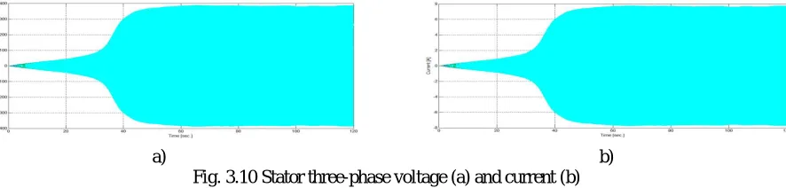
As shown in fig.3.1, the wind turbine model has the random wind, pitch angle control signal and its speed feedback as an input. The output of the turbine is mechanical power on its shaft which is coupled to the permanent magnet synchronous generator through the gearbox. The gearbox outputs are the shaft torque and corresponding speed of the synchronous generator which are stepped down and stepped up, respectively, of the wind turbine shaft speed and torque. The outputs of the Synchronous generator monitored are the three phase stator current and the three phase voltages. Instantaneous power is generated from the three phase voltages and currents using multipliers and adders of MATLAB/SIMULINK as shown in the block diagram. The product of synchronous generator shaft torque and the generator rotational speed also provide the mechanical input power to the generator. Figure 3.2 shows the random wind speed generated by wind model for 120 seconds while fig.3.3 is the pitch angle controller respond as the result of the PI controller.
Fig. 3.4 is turbine shaft rotational speed optimized and reached its steady state after 50 seconds while fig.3.5 is the torque generated on the turbine shaft. As it can be observed from these two figures, the start up speed and torque comply with the dynamic transient state of rotating machines.
Fig. 3.4 Turbine shaft rotational speed Fig. 3.5 Torque on the Turbine shaft
Fig. 3.6 shows the mechanical power output on the turbine shaft (5kW) as calculated from the turbine shaft torque and speed. Fig. 3.7 is the speed of synchronous generator which is about 900 radians per second which corresponds to 143 Hz frequency.
Fig. 3.6 Turbine power Fig. 3.7 Synchronous generator rotational speed
Fig. 3.8 shows the mechanical power input to the synchronous generator shaft while fig.3.9 shows the output electrical power of the machine. The delivered mechanical power has been converted in to electrical power by a PMSG and the output 3-phase electrical power is measured to be 4.5kw as shown in fig.3.9. The output, 3-phase electrical power is obviously less than the input power due to the encountered mechanical and electrical losses within the conversion process.
Fig. 3.8 Mechanical power on the shaft of SG Fig. 3.9 Three-phase electrical power
a) b) Fig. 3.10 Stator three-phase voltage (a) and current (b)
IV. CONCLUSION AND FUTURE WORK
4.1 Conclusion
In this work, dynamic simulation model for wind energy conversion system has been integrated with latest version of MATLAB/SIMULINK and used to simulate a 5 kW wind energy conversion system. The simulation result demonstrates that the power output corresponds to the intermittent wind speed and is in agreement with the expected signal values. The designed PI pitch controller also controls the turbine pitch angle following the variation of wind speed to the desired average value within 120 seconds. Furthermore, the provision of intermediate variable monitoring points between models and the possibility of parameter adjustment make the design of WECS and control system tuning very easy and fast.
4.2 Future Work
The system model can be extended to design and analysis of grid connected WECS by incorporating the static power converter modules. Inclusion of the converter modules and experimental verification of the system is underway.
REFERENCES
[1] Abo-Khalil, A.G.; Dong-Choon Lee. “Dynamic modeling and control of wind turbines for grid-connected wind generation system”. IEEE
37th Power Electronics Specialists Conference, pp. 1 – 6, 2006.
[2] Arifujjaman, M.; Iqbal, M.T.; Ouaicoe, J.E.; Khan, M.J. “Modeling and control of a small wind turbine”IEEE Canadian Conference on
Electrical and Computer Engineering, pp. 778-781, 2005.
[3] Das, M.K.; Chowdhury S.P.; Chowdhury S.; Domijan A.“Dynamic Modeling and Performance Analysis of a DFIG Wind Energy Conversion
System” IEEE Conference on Power and Energy Society General Meeting - Conversion and Delivery of Electrical Energy in the 21st Century, pp. 1 – 5, 2008.
[4] F. Iov, A.D. Hansen, P.Sorensen, F. Blaabjerg. “Wind turbine Block set in Matlab/Simulink”. General overview and description of the
models”. Aalborg University, March 2004.
[5] Frede Blaabjerg and Zhe Chen, Power Electronics for Modern Wind Turbines. Morgan & Claypool Publishers, USA, 2006.
[6] Iov, F.; Blaabjerg, F.; Zhe Chen; Hansen, A.D.; Sorensen, P. A. “New Simulation Platform to Model, Optimize and Design Wind Turbines”.
IEEE 28th Annual Conference of the Industrial Electronics Society, vol.1, pp. 561 – 566, 2002.
[7] Kojabadi, H.M.; Liuchen Chang; Boutot, T. “Development of a Novel Wind Turbine Simulator for Wind Energy Conversion Systems using
an Inverter-Controlled Induction Motor” IEEE Transactions on Energy Conversion, Volume: 19, Issue: 3, pp. 547 – 552, 2004.
[8] Manwell J.F. and McGowan J.G. Wind Energy Explained: theory, design and application.
John Wiley & Sons Ltd, Great Britain, 2009.
[9]. Ofualagba, G.; Ubeku, E.U. “Wind Energy Conversion System- Wind Turbine Modeling” IEEE Conference on Power and Energy Society
General Meeting - Conversion and Delivery of Electrical Energy in the 21st Century, pp.1 – 8, 2008.
[10] Olimpo Anaya-Lara … [et al.], Wind Energy Generation: modeling and control. Wiley & Sons Ltd, Great Britain, 2009.
[11] Shaolin Li; Xing Zhang; Zhen Xie; Shuying Yang; Chongwei Zhang; Renxian Cao. “A Study on Dynamic Model and Analysis of Wind
Turbine Generation System” IEEE Power and Energy Engineering Conference Asia-Pacific, pp.1 – 4, 2010.
[12] Slootweg, J.G.; Polinder, H.; Kling, W.L. “Dynamic Modeling of a Wind Turbine with Doubly Fed Induction Generator” IEEE Conference
on Power Engineering Society Summer Meeting, vol.1, pp. 644 – 649, 2001.
[13] W.L. Kling, H. Polinder, J.G.Slootweg. “Dynamic modeling of a wind turbine with DFIG” Power engineering society summer meeting,
Vancover-Canada, July 2001.
[14] Weihao Hu; Yue Wang; Xianwen Song; Zhaoan Wang. “Development of Wind Turbine Simulator for Wind Energy Conversion Systems
based on Permanent Magnet Synchronous Motor” IEEE International Conference on Electrical Machines and Systems, pp. 2322 – 2326, 2008.
[15] Wu Xueguang; Wang Weisheng; Dai Huizhu; Chen Yunping. “Application of Models of the Wind Energy Conversion System to Wind Power

![Fig. 2.2 Simulink model of the wind turbine rotor [4].](https://thumb-us.123doks.com/thumbv2/123dok_us/7773844.1281136/4.595.143.453.697.763/fig-simulink-model-of-the-wind-turbine-rotor.webp)

![2 [(2,4 Dimethylphenyl)iminomethyl] 6 methylphenol](data:image/gif;base64,R0lGODlhAQABAIAAAP///wAAACH5BAEAAAAALAAAAAABAAEAAAICRAEAOw==)