Power Quality Improvement of Distribution
System using HCC Based FACTS Controller
N.Ramesh
Assistant Professor, Department of Electrical & Electronics Engineering, Malla Reddy College of Engineering &
Technology, Secunderabad, Telangana, India
ABSTRACT: Recent industrial equipments are more sensitive to power quality problems than before and need higher quality of electrical power. Power electronic based power processing offers higher efficiency, compact size and better controllability. But on the flip side, due to switching actions, these systems behave as non-linear loads. This creates power quality problems such as voltages Sag/Swell, flickers; harmonics, asymmetric of voltage have become increasingly serious. At the same time, modern industrial equipments are more sensitive to these power quality problems than before and need higher quality of electrical power. This VSI draw or supply a compensating current from the utility such that it cancels current harmonics on the AC side. STATCOM generates a current wave such that it compensate by cancelling out the non-linear current waveform generated by load. The Simulations are done by using Matlab/Simulink software.
KEYWORDS: Linear loads, Non-Linear loads, Power Quality, Harmonics, Voltage Source Inverter.
I.INTRODUCTION
Flexible AC Transmission System (FACTS) devices become more commonly used as the regulated power supply in various power sectors. So the FACTS devices with control strategy have the potential to significantly improve the stability margin, can also control power flow (both active and reactive power). They also allow increased utilization of existing network closer to its thermal loading capability and avoid the need to construct new transmission lines.
Modern electric power system is facing many challenges due to day by day increasing complexity in their operation and structure. In the recent past, one of the problems that got wide attention is the power system instability. With the lack of new generation and transmission facilities and over exploitation of the existing facilities geared by increase in load demand make these types of problems more imminent in modern power systems. Demand of electrical power is continuously rising at a very high rate due to rapid industrial development. To meet this demand, it is essential to raise the transmitted power along with the existing transmission facilities. The need for the power flow control in electrical power systems is thus evident. With the increased loading of transmission lines, the problem of transient stability after a major fault can become a transmission power limiting factor.
II.SYSTEM DESCRIPTION
Fig.1 shows the basic compensation principle of shunt active power filter. A voltage source inverter (VSI) is used as the shunt active power filter [3]. This is controlled to generates a current wave such that it compensate by cancelling out the nonlinear current waveform generated by load i.e. this active power filter (APF) generates the nonlinearities opposite to the load nonlinearities. Fig. 2 shows the different waveforms i.e. the load current, desired source current and the compensating current injected by the shunt active power filter which contains all the harmonics, to make the source current purely sinusoidal. This is the basic principle of shunt active power filter to eliminate the current harmonics and to compensate the reactive power.
LOAD
V
sP
s=PfQ
s=0I
sI
L
I
ENon-Linear Load
Q
c=Ph+PLossQ
c=Qf+Qh Fig.1. Basic Compensation TechniqueFig.2. Waveforms for the actual load current, desired source current and the compensating current
Total instantaneous power drawn by the nonlinear load can be represented as
PL(t)=Pf(t)+Pr(t)+Ph(t) (1)
From the single line diagram
is (t) = iL (t)+ic(t) (2)
The utility voltage is given by
iL(t)=∑ In sin(nωt+ϕn) (4)
Instantaneous load power pL(t) can be expressed as
PL(t) = vs(t) iL(t) (5)
The term pr(t)represents the reactive power and the term ph(t) t represents the harmonic power drawn by the load. For
ideal compensation only the real power (fundamental) should by supplied by the source while all other power components (reactive and the harmonic) should by the active power filters i.e.
pc(t) = pr(t) + ph(t) be supplied
Pr(t) = Vm I1 sin2 ωt cosϕ1 (6)
If active power filter provide the total reactive and harmonic power, then is(t) will be in phase with the utility and pure
sinusoidal. At this time, the active filter must provide the following compensation current
is(t) = pr(t)/vs(t) (7)
The ideal compensation requires the mains current to be sinusoidal and in phase with the source voltage irrespective of load current nature. Hence, the desired source currents after compensation can be given as
Isa *
= Imax sinωt
Isa* = Imax sin(ωt-2π/3)
Isa* = Imax sin(wt-4π/3)
III.DESIGN OF STATCOM
STATCOM is operated in hysteresis control mode to regulate the load reactive power and eliminate harmonics from the supply currents. Mainly design includes capacitor, Hysteresis controller based PI controller, unit vector template.
A. Design of Capacitor
The reference value of the capacitor voltage Vdc ref is selected mainly on the basis of reactive power compensation capability. For satisfactory operation the magnitude of Vdc ref should be higher than the magnitude of the source voltage V s . By suitable operation of switches a voltage Vc having fundamental component Vc1is generated at the ac side of the inverter. This results in flow of fundamental frequency component I s1, as shown in Fig. 2. The phasor diagram for Vc1>Vs representing the reactive power flow is also shown in this figure. In this Is1represent fundamental component.
PWM
Converter
V
dc
Cf
V
c1
Lf
V
s
Is1 Vs Vc1
Ic1 jwLcIc1
IL1
Fig.3. Single line and vector diagrams for STATCOM
B. Design of PI controller
The controller used is the discrete PI controller that takes in the reference voltage and the actual voltage and gives the maximum value of the reference current depending on the error in the reference and the actual values [6]. The mathematical equations for the discrete PI controller are: The voltage error V(n) is given as:
V(n) = V*(n) – V(n) (8)
The output of the PI controller at the nth instant is given as:
I(n) = I(n-1)+Kp[V(n)-V(n-1)]+KiV(n) (9)
When the DC link voltage is sensed and compared with the reference capacitor voltage, to estimate the reference current, the compensated source current will also have sixth harmonic distortion for three-phase system and second harmonics distortion for single phase system. A low pass filter is generally used to filter these ripples which introduce a finite delay and affect the transient response. To avoid the use of this low pass filter the capacitor n voltage is sampled at the zero crossing of the source voltages.
V
DCV
DC(ref)PI
Controller
π
Reference Current
Template
V
DC+
-+
-Hysterisis
Current
Control
I
sSTATCOM
I
s(ref)
C. Hysteresis Controller
Reference
Wave
Hysterisis
Band 2HB
Upper Band HB
Lower Band HB
Actual
Current
PWM Voltage
Wave
Lower Switch
Upper Switch
wt
wt
0
π
0
+0.5 V
dc-0.5 V
dcFig.5. Basic principal of hysteresis controller
With the hysteresis control, limit bands are set on either side of a signal representing the desired output waveform [6]. The inverter switches are operated as the generated signals within limits. The control circuit generates the sine reference signal wave of desired magnitude and frequency, and it is compared with the actual signal. As the signal exceeds a prescribed hysteresis band, the upper switch in the half bridge is turned OFF and the lower switch is turned ON. As the signal crosses the lower limit, the lower switch is turned OFF and the upper switch is turned ON. The actual signal wave is thus forced to track the sine reference wave within the hysteresis band limits.
D. Pulse Generation Technique
AND
NOT
AND
AND
NOT
AND
AND
NOT
AND
1
Ias
Ia*
I
bsI
b*
I
csI
c*
2
4
3
6
5
-+
-+
-+
2
1
4
6
3
5
S2
S1
S4
S3
S6
S5
7
time
Fig.6. Pulse generation diagram
E. Extraction of Unit Vector Template
The schematic diagram of unit vector template generation [7] is shown in Fig. 7
1
Discrete
RMS
Discrete
RMS
Discrete
RMS
K
K
K
x
x
x
1
DRMS
DRMS1
DRMS2
Gain
Gain1
Gain2
In1
Out1
Product
Product1
Product2
Fig.7. Extraction of unit vector template
IV. MATLAB MODELEING AND SIMULATION RESULTS
Fig.8 Matlab/Simulink of Proposed STATCOM-Power Circuit
Fig.8 Matlab/Simulink Model of proposed power circuit, along with control circuit.
Un-Balanced Non-Linear Load Condition
Fig. 9 Simulation results of Non-Linear Unbalanced Load (a) Source Current (b) Load Current (c) Compensating Current.
Fig.9 shows the Simulation results of Non-Linear Unbalanced Load, source current, load current respectively.
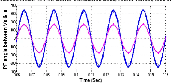
Fig.10 Simulation Results Power Factor For Un-Balanced Non- Linear Load
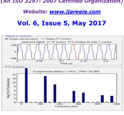
Fig.11 FFT Analysis of Phase-A Source Current for Un-Balanced Non-Linear Load
Fig.11 shows the FFT Analysis of Phase-A Source Current for Un-Balanced Non-Linear Load, here we get 19.38%.
Fig. 12 FFT Analysis of Phase-A Source Current for Un-Balanced Non-Linear Load
Fig.12 shows the FFT Analysis of Phase-A Source Current for Un-Balanced Non-Linear Load, here we get 2.76%.
V.CONCLUSION
STATCOM is most effective for harmonic compensation. Different types, such as shunt and series active power filters are used effectively. Power quality and custom power have become topics of research interest because of widespread use of non-linear loads such as diode/thyristor rectifiers, SMPS, UPS, induction motor drives. A very simple hysteresis current controller based control technique with help of unit vector template is proposed for STATCOM. A MATLAB/Simulink based model has been simulated. Simulation result shows the input current harmonics produced by nonlinear load is reduced after using the control strategy. FFT analysis shows the reduction in THD is remarkable.
REFERENCES
[1] Rakesh Kantaria and S.K.Joshi “A review on power quailty problems and solutions” Power electronics National Conference November 2008. [2] Bhim Singh, Ambrish Chandra and Kamal Al-Haddad “A Review of Active Filters for Power Quality Improvement” IEEE Trans. Ind. Electronics, VOL. 46, NO. 5, pp 960-971 OCTOBER 1999
[3] Understanding FACTS: Concepts and Technology of Flexible AC Transmission Systems. Narain G. Hingorani, Laszlo Gyugyi. Wiley IEEE press.
[4] Amit Jain, Ned Mohan, Karan Joshi and Aman Behal "voltage Regulation with STATCOMS:Modeling ,Control and Results." IEEE Transactions on Power Delivery, Vol 21, NO. 2, April 2006 PP 726- 734.
[7] Vadirajacharya.K , Pramod Agarwal and H.O.Gupta,“A Simple Control Strategy ForUnified Power Quality Conditioner Using Current Source Inverter” The 8th International Power Engineering Conference – IPEC2007 3-6 December 2007, Singapore
[8] Y.Kolhatkar, P.A.Agraval, A.O.Barry and T.D.Nguyen,; “A simple New Control Technique for Unified Power Quality conditioner (UPQC), The 11th International Conference on Harmonics and Quality of Power 2004.