User’s Guide
436-0013-10, Rev 100
Thermal Imaging Overview
The FLIR Vue Pro camera is a state-of-the-art thermal imaging system. The system is easy to use, but it is useful to understand how to interpret what is displayed on the monitor.
The FLIR Vue Pro camera does not produce images from visible light like the human eye does. The camera relies on the fact that all objects, even very cold objects like ice, emit thermal (heat) energy in the portion of the spectrum that the camera can see, the long wave infrared (LWIR). Unlike a visible-light camera, the FLIR Vue Pro camera produces images based on radiated rather than reflected energy.
Because there is no color in heat images, these “temperatures” are processed by Automatic Gain Control (AGC) into a maximum of 256 “shades of gray” to display as a thermal video image and a still image JPEG. Since the imaging system is sensitive enough to distinguish many more than 256 different temperatures, each “shade of gray” represents a range of temperatures. The AGC settings
provide control over how the original thermal image is processed. See Automatic Gain Control.
Raw scene data, which is not processed by the AGC, is available as still images—TIFF and FLIR
File Format (FFF)—for post processing using image processing software. See File Formats.
FLIR offers a selection of training courses to help you to get the best performance and value from your FLIR Vue Pro camera. You can find out more at the FLIR training Web page:
http://www.infraredtraining.com.
This guide shows how easy it is to get the plug-and-play FLIR Vue Pro connected, running, and mounted. The camera does not have an on or off switch. When power is applied, IR video will be shown in less than five seconds and the Bluetooth radio is enabled in about 30 seconds (three beeps are sounded and the Bluetooth LED is lit blue).
What’s in the Box?
FLIR Vue Pro comes with the following components:
• FLIR Vue Pro thermal camera with Camera Mount
• Bench Cable—for connecting FLIR Vue Pro to a computer USB port for power and file transfer;
and to a video monitor for testing.
• MicroSD Card (32 GB maximum)—for storing images/video and upgrading camera firmware.
• Accessory Cable—for connecting FLIR Vue Pro to a MAVLink compatible Autopilot.
See Accessory Cable Pinout Definition.
M2X0.4 threaded mounting holes on the camera’s left side, right side, and bottom (mounting screws not included) 10-pin mini-USB
7-pin Accessory Port ¼-20 Threaded Mounting Hole Lens Lens Barrel Port Camera Mount MicroSD Card Connect to Camera 10-pin mini-USB port Connect to
Video Monitor
Connect to Computer USB port
PN 4142005
Connect to Camera
7-pin port MAVLink
PWM 3 PWM 4 PN 4142156
A Quick Tour
Power up
• Status LED blinks red for approximately 30 seconds, then changes to solid blue. Bluetooth is
now enabled. FLIR Vue Pro beeps three times and the Record LED goes from off to solid green. (If the FLIR Vue Pro is connected to a computer, the Record LED blinks green.)
• Start the App on the mobile device. Use the App to configure camera settings, if required, and
then to disable the Bluetooth radio in preparation for flight.
• FLIR Vue Pro is ready. Press the Record button on the camera or in the App to start recording
or use PWM signals setup on the Autopilot. Record LED blinks green while recording video, or flashes yellow each time it captures a still image.
See The FLIR Vue Pro App for instructions on camera modes, video/still image formats, PWM settings, and other configuration options.
Mounting FLIR Vue Pro
FLIR Vue Pro has a variety of mounting options.
Screw a standard tripod ¼-20 bolt into the threaded insert located on the top surface of the camera. Do not exceed 6.35 mm [0.25 in] maximum depth or warranty is void.
FLIR Vue Pro has two threaded mounting holes on each side, as well as on the camera bottom.
These threaded holes, 24 mm (0.945 in) apart accept M2x0.4 screws (not included). Do not exceed 4.0 mm [0.157 in] maximum depth or warranty is void.
Refer to the FLIR Vue Pro Technical Drawing for additional
information. button/LED System Status/Bluetooth
Status LED at power up—red blinking
button/LED
Status LED at ready—blue, Bluetooth is enabled
Use the FLIR Vue Pro Mobile App to configure camera. Press record button to start recording.
Record LED recording alert—blinks yellow
Record Status
Record LED at power up—off Record LED at ready—solid green
(for example, no microSD present, microSD full, microSD in use by PC) Status LED firmware upgrade—blinks purple
Record LED blinks red when recording video
Record LED blinks yellow when a still image is captured Press Status/Bluetooth button—solid blue
¼-20 Insert
Side and Bottom Mounting Holes
Camera Mount
The included Camera Mount allows using standard action camera mounts. If a different mounting option will be used, it can be removed using the following steps:
When installing the Camera Mount, be sure to engage the two alignment pins with the corresponding holes on the camera body.
Connecting and Powering the FLIR Vue Pro
FLIR Vue Pro is compatible with common 10-pin mini-USB cables that are used to provide power to, and get video from, action cameras commonly mounted on a small unmanned aerial system
(sUAS). Refer to the camera Interface FLIR Vue Pro Technical Drawing located on the FLIR web
page for information for constructing cables or changing cable connectors.
A number of vendors sell cables that are compatible with video transmitters which supply the 5 Vdc, 750 mA power the FLIR Vue Pro needs. Connect the video transmitter per the manufacturer’s instructions.
Unscrew the Lens Nut Slide the Camera Mount off Screw the Lens Nut back on
Video Transmitter cable:
White – not used
10-pin Mini USB plug
Pin 2 – 5Vdc power in Pin 2 Pin 10 Pin 7 Pin 5 Pin 5 – Video GND Pin 7 – Video Out Pin 10 – ground
Yellow – Video Out Black – ground Red – 5Vdc power in
Another example of a compatible cable which provides discrete connectors for power and video is shown below.
Simply plug the chosen cable into the mini-USB port on the FLIR Vue Pro, connect the power plug to an appropriate regulated power supply, and the video plug to the video transmitter.
Caution on powering FLIR Vue Pro:
• FLIR Vue Pro does not have over-voltage or reverse polarity protection. Only use a filtered,
regulated 5Vdc power source with the FLIR Vue Pro! Applying more than 6Vdc or reversing polarity will damage the camera and void the warranty.
Connecting to a Pixhawk Flight Controller
The FLIR Vue Pro Accessory cable is software and connector compatible with the Pixhawk Autopilot. Other flight controllers or I/O modules may require different cables or connectors. Refer to the FLIR Vue Pro Technical Drawing located on the FLIR web page for detailed information.
Discrete Power/Video connectors
5Vdc power in Video Out Video GND Power ground Pin 2 Pin 10 Pin 7 Pin 5 Red – 5Vdc power in Black – ground Yellow – video out White – not used
P1 P3
P4 P2 To Pixhawk TELEM 1
To Pixhawk AUX out (1-6)
To Pixhawk AUX out (1-6) Hirose Plug Part Number
P1 - DF13-7S-1.25C P2 - DF13-6S-1.25C P3, P4 - M20-1060300
TELEM 1
P3 and P4 to Aux Out programmed ports
The FLIR Vue Pro App
Use the App to make changes to video format, image orientation, scene or color palette, and communication options. Download and install the FLIR Vue Pro App from Google Play or Apple App Store.
1. If required, press the Bluetooth button on the camera. LED will be lit blue to indicate Bluetooth is active. 2. Start the App.
3. Wait while the App connects.
4. When connected, the Home screen appears. (The last screen accessed will be shown.)
The Home screen shows camera status and allows choosing the Color Palette, Scene Presets, AGC Settings, and image output (video or still).
Table 1: Accessory Cable Pinout Definition P1 - Accessory Port
(DF13-7S-1.25Ca)
a. All cable plug part numbers are Hirose.
Wire color P2 - MAVLink (DF13-6S-1.25Ca) P3 - AUX Out (M20-1060300a) P4 - AUX Out (M20-1060300a) PWM_1 1 green RX in 3 PWM_2 2 white TX out 2 GND 3 black GND 6 PWM_3 4 orange PWM_3 1 GND 5 black GND 3 PWM_4 6 blue PWM_4 1 GND 7 black GND 3 Go to Settings Screen
Automatic Gain Control
• Color Palette
WhiteHot and BlackHot are the primary palettes used in thermal imaging. The image has been described as containing 256 “shades of gray” each representing a different temperature range present in the scene. A variety of color palettes may provide better contrast when viewed with the naked eye, under certain conditions. Different color palettes can provide very different results in the image. Their appeal is based on personal preference.
• Scene Presets
Each Scene Preset provides a combination of automatic gain control (AGC) settings which have been optimized by FLIR Systems to provide the best image for each particular application. In most cases these Scene Presets will be all the camera setup required. Individual settings may be optimized depending upon scene content and viewing or recording preferences. • Sharpness (DDE), higher values increase Sharpness,
while lower values soften (blur) the image and filter fixed pattern noise.
• Active Contrast Enhancement (ACE), provides a contrast adjustment based on the relative scene temperature. Values greater than 0 give more contrast to the hotter content and decrease contrast for the colder content. Values less than 0 do the opposite by decreasing the contrast for hotter content and leaving more of the “shades of gray” to represent the colder content.
• Smart Scene (SSO), determines the percentage of the scene that will be allotted a linear mapping. When enabled, the difference in gray shades between two objects is more representative of the difference in temperature, although the optimization in local contrast can be lost.
• Recalibrate, manually initiates a flat field correction (FFC) that updates the pixel calibration to improve image quality. An internal shutter is closed (a click can be heard) behind the lens to provide a uniform temperature to all pixels. FFC is also performed automatically, based on elapsed time and during changes in temperature.
Main Settings
• Analog Video Format
Select NTSC or PAL as the format of the video that is output to the 10-pin mini USB port. This setting does not affect the format of the video that is saved to the microSD card.
• File Type
Select formats for still images and video saved to the microSD card.
• Flip Horizontal/Vertical
To mount the camera upside down, flip both Horizontal and Vertical.
• Speaker and LED On/Off
Even when turned off, the Status/Bluetooth LED will blink during power up and the speaker will beep three times when the camera is ready.
• Disable Bluetooth
Powers down the Bluetooth radio on the camera. The camera will normally disable the
Bluetooth after two minutes of inactivity. See Persistent Bluetooth.
PWM Settings
With the accessory port and accessory cable, functions can be controlled directly from the sUAS flight controller via PWM signals (refer to the controller manual for instructions, as every brand of controller is a little different).
Any function can be assigned to any Channel, but no two channels can be assigned to the same function. PWM 3 and PWM 4 are the signals available with the standard accessory cable.
1. Select a channel to configure an action.
Select a Channel
2. Select Number of States.Either a two- or three-position switch is located on the controller.
3. Assign functions to the available states for each signal. 4. Program the radio to provide signals to the Aux Out ports
for accessory cable P3 and P4.
About Settings
The About screen provides information about the current software and FLIR Vue Pro.
• Persistent Bluetooth
Normally, the camera will disable the Bluetooth radio after two minutes of inactivity to ensure that the camera radio will not interfere with any flight control communications.
Turn ON Persistent Bluetooth to keep the camera connected while working in the App. Once the App is disconnected, the Bluetooth radio will be disabled after two minutes.
• Available Upgrade
When the camera detects a new firmware upgrade file on the microSD card, the Upgrade Available dialog will start. Chose YES to upgrade the firmware. The dialog will start any time the camera or the App is started.
File Formats
The Vue Pro can save image data in a number of file formats, each with unique characteristics.
• JPEG is a compressed 8-bit image with Scene and Palette processing applied.
• TIFF is uncompressed 14-bit raw sensor data with no post processing.
The following links provide information on viewing 14-bit TIFF images.
ImageJ, Matlab, Pix4Dmapper Discovery.
• FFF has both the compressed 8-bit processed JPG image and 14-bit raw
sensor data in a single file. This format is exclusively for use with FLIR software.
FLIR Vue Pro Specifications
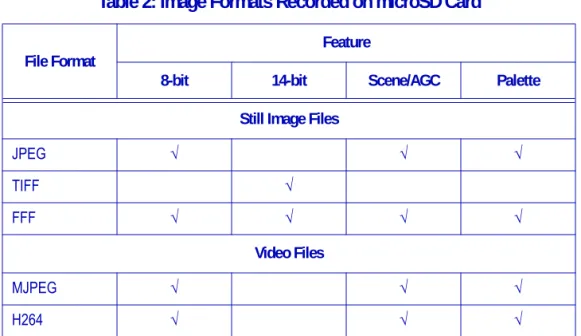
Table 2: Image Formats Recorded on microSD Card File Format
Feature
8-bit 14-bit Scene/AGC Palette Still Image Files
JPEG √ √ √ TIFF √ FFF √ √ √ √ Video Files MJPEG √ √ √ H264 √ √ √ Overview
Thermal Imager Uncooled VOx Microbolometer
Resolution 640x512 336x256 Lens Options 9 mm; 69° x 56° 13 mm; 45° x 37° 19 mm; 32° x 26° 6.8 mm; 45° x 35° 9 mm; 35° x 27° 13 mm; 25° x 19° Spectral Band 7.5 μm - 13.5 μm
Full Frame Rates 30 Hz (NTSC); 25 Hz (PAL) US only, not for Export Exportable Frame Rates 7.5 Hz (NTSC); 8.3 Hz (PAL)
On-board Storage microSDHC
Minimum speed, Class 4 Maximum size, 32GB
Physical Attributes
Size 2.47" x 1.75" (62.7 mm x 44.5 mm) (including lens) Weight 3.56 oz to 4.30 oz (101 g to 122 g) (configuration
Care of FLIR Vue Pro
• Only power FLIR Vue Pro with a regulated 5 Vdc power source. Using more than 6 Vdc will
damage the camera and void the warranty.
• Do not touch the lens. If the lens gets dirty, a light dusting of air should dislodge any dust
particles. If the lens is still noticeably dirty, use 75% Isopropyl alcohol and lens tissue. Use a light wiping motions with a fresh section of lens tissue with each swipe so as not to drag dust or dirt particles back over the lens surface
• FLIR Vue Pro is neither water nor dust resistant. Care for it as you would any valuable piece of
electronics equipment.
Image Processing & Display Controls
Image Optimization for sUAS Yes
Digital Detail Enhancement Yes - Adjustable in App
Invertable Image Yes - Adjustable in App
Polarity Control (BlackHot/WhiteHot) and Color Palettes Yes - Adjustable in App
Power
Input Supply Voltage 4.0 Vdc to 6.0 Vdc
Power Dissipation, steady state (max 3.9 W during shutter event of approximately 0.5 seconds)
<2.6 W <2.6 W
Environmental
Operating Temperature Range -20 °C to +50 °C
Non-Operating Temperature Range -55 °C to +95 °C