Waspmote Digimesh
Networking Guide
Document version: v1.0 - 11/2012
© Libelium Comunicaciones Distribuidas S.L.
Index
INDEX
1. Hardware ... 5
2. General Considerations ... 7
2.1. Waspmote Libraries ...7
2.1.1. Waspmote XBee Files ...7
2.1.2. Constructor ...7
2.2. API Functions ...7
2.3. API extension ...8
2.4. Waspmote reboot ...8
2.5. Constants pre-defined ...8
2.6. XBee modules supported ...8
3. Initialization ... 9
3.1. Initializing ...9 3.2. Setting ON ...11 3.3. Setting OFF ...114. Node Parameters ... 12
4.1. MAC Address ...12 4.2. PAN ID ...12 4.3. Node Identifier ...12 4.4. Channel...13 4.5. Network Hops...144.6. Network Delay Slots ...14
4.7. Network Route Requests ...15
4.8. Mesh Network Retries ...15
5. Packet Parameters ... 16
5.1. Structure used in packets ...16
5.2. Maximum payloads ...19
6. Power Gain and Sensibility ... 20
6.1. Power Level ...20
6.2. Received Signal Strength Indicator ...21
7. Connectivity ... 22
7.1. Topologies ...22
7.2. DigiMesh Architecture ...22
7.2.1. Routing ...23
Index
7.3. Connections ...23
7.3.1. Unicast ...23
7.3.2. Broadcast ...23
7.4. Sending Data ...23
7.4.1. API Frame Structure ...23
7.4.2. Application Header ...24
7.4.3. Fragmentation ...25
7.4.4. Structure packetXBee ...25
7.4.5. Sending without API header ...25
7.4.6. Examples ...25
7.5. Receiving Data ...27
7.5.1. Examples ...28
7.6. Discovering and Searching Nodes ...30
7.6.1. Structure used in Discovery ...30
7.6.2. Searching specific nodes ...31
7.6.3. Node discovery to a specific node ...31
8. Starting a Network ... 32
8.1. Choosing a channel ...32
8.2. Choosing a PAN ID ...32
9. Joining an Existing Network ... 33
9.1. Network parameters are known ...33
9.1.1. Channel ...33
9.1.2. PAN ID ...33
9.2. Network parameters are unknown...33
9.3. Node Discovery ...33
9.3.1. Node Discovery Function ...33
9.3.2. Node Discovery Time ...34
10. Sleep Options ... 35
10.1. Sleep Modes ...35
10.1.1. Asynchronous Cyclic Sleep ...35
10.1.2. Synchronous Cyclic Sleep ...35
10.2. Sleep Parameters ...35
10.2.1. Sleep Mode ...35
10.2.2. Sleep Period ...36
10.2.3. Time Before Sleep ...36
10.2.4. Sleep Options ...36
10.2.5. Sleep Status ...37
10.2.6. Missed synchronizations count ...37
10.2.7. Operational sleep period ...37
10.2.8. Operational wake period ...38
Index
11. Synchronizing the Network ... 39
11.1. Operation ...39
11.1.1. Synchronization Messages ...39
11.2. Becoming a Sleep Coordinator ...39
11.2.1. Synchronization Messages ...39
11.2.2. Nomination and Election ...39
11.2.3. Changing Sleep Parameters ...40
11.3. Configuration ...40
11.3.1. Starting a Sleeping Network ...40
11.3.2. Adding a New Node to an Existing Network ...40
11.3.3. Changing Sleep Parameters ...40
11.3.4. Rejoining Nodes Which Have Lost Sync ...41
12. Security and Data Encryption ... 42
12.1. DigiMesh Security and Data encryption Overview ...42
12.2. Security in API libraries ...42
12.2.1. Encryption Enable ...42
12.2.2. Encryption Key ...43
12.2.3. Maximum Data Payloads ...43
12.3. Security in a network ...44
12.3.1. Creating a network enabling security ...44
12.3.2. Joining a security enabled network ...44
Hardware
1. Hardware
The XBee-802.15.4 and XBee-900 modules can use an optional firmware (DigiMesh) so that they are able of creating mesh networks instead of the usual Star topoplogy. This firmware has been developed by Digi aimed for allowing modules to sleep, synchronise themselves and work on equal terms, avoiding the use of node routers or coordinators that have to be permanently powered on. Characteristics of the implemented protocol:
• Self Healing: any node can join or leave the network at any moment.
• P2P architecture: all nodes are equal. There are no father-son relationships.
• Silent protocol: reduced routing heading due to using a reactive protocol similar to AODV (Ad hoc On-Demand Vector Routing).
• Route discovery: instead of keeping a route map, routes are discovered when they are needed.
• Selective ACKs: only the recipient responds to route messages.
• Reliability: the use of ACKs ensures data transmission reliability.
• Sleep Modes: low energy consumption modes with synchronisation to wake at the same time.
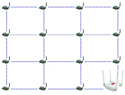
The classic topology of this type of network is mesh, as the nodes can establish point to point connections with brother nodes through the use of parameters such as the MAC or network address or by making multi-jump connections.
Figure 1: Mesh topology
DigiMesh 2.4GHz
Module Frequency Tx Power Sensitivity Channels Distance
Normal 2,40 – 2,48GHz 1mW -92dBm 16 500m
PRO 2,40 – 2,48GHz 100mW -100dBm 13 7000m
The XBee DigiMesh modules share the hardware module with the XBee-802.15.4, being able to pass from one to the other by changing the firmware. For this reason, the characteristics relating to the hardware are the same, changing those related with the protocol used.
Hardware DigiMesh 900MHz
Frequency Tx Power Sensitivity Channels Distance
902-928MHz 50mW -100dBm 12 10km
The XBee DigiMesh modules share the hardware module with the XBee-900, being able to pass from one to the other by changing the firmware. For this reason, the characteristics relating to the hardware are the same, changing those related with the protocol used.
General Considerations
2. General Considerations
2.1. Waspmote Libraries
2.1.1. Waspmote XBee Files
WaspXBeeCore.h ; WaspXBeeCore.cpp, WaspXBeeDM.h, WaspXBeeDM.cpp
2.1.2. Constructor
To start using the Waspmote XBee DigiMesh library, an object from class ‘WaspXBeeDM’ must be created. This object, called ‘xbeeDM’, is created inside the Waspmote XBee DigiMesh library and it is public to all libraries. It is used through the guide to show how Waspmote XBee DigiMesh library works.
When creating this constructor, some variables are defined with a value by default.
2.2. API Functions
Through the guide there are many examples of using parameters. In these examples, API functions are called to execute the commands, storing in their related variables the parameter value in each case.
Example of use
{
xbeeDM.getOwnMacLow(); // Get 32 lower bits of MAC Address xbeeDM.getOwnMacHigh(); // Get 32 upper bits of MAC Address }
Related Variables
xbeeDM.sourceMacHigh[0-3] → stores the 32 upper bits of MAC address xbeeDM.sourceMacLow [0-3] → stores the 32 lower bits of MAC address
When returning from ‘xbeeDM.getOwnMacLow’ the related variable ‘xbeeDM.sourceMacLow’ will be filled with the appropriate values. Before calling the function, the related variable is created but it is empty.
There are three error flags that are filled when the function is executed:
• error_AT: it stores if some error occurred during the execution of an AT command function
• error_RX: it stores if some error occurred during the reception of a packet
• error_TX: it stores if some error occurred during the transmission of a packet
All the functions return a flag to know if the function called was successful or not. Available values for this flag:
• 0: Success. The function was executed without errors and the variable was filled.
• 1: Error. The function was executed but an error occurred while executing.
• 2: Not executed. An error occurred before executing the function.
• -1: Function not allowed in this module.
To store parameter changes after power cycles, it is needed to execute the writeValues function. Example of use
{
xbeeDM.writeValues(); // Keep values after rebooting }
General Considerations
2.3. API extension
All the relevant and useful functions have been included in the Waspmote API, although any XBee command can be sent directly to the transceiver using the ‘sendCommandAT‘ function.
Example of use
{
xbeeDM.sendCommandAT(“CH#”); // Executes command ATCH }
Related Variables
xbeeDM.commandAT[0-100] → stores the response given by the module up to 100 bytes
2.4. Waspmote reboot
When Waspmote is rebooted or it wakes up from a deep sleep state (battery is disconnected) the application code will start again, creating all the variables and objects from the beginning.
2.5. Constants pre-defined
There are some constants pre-defined in a file called ‘WaspXBeeConstants.h’. These constants define some parameters like the size of each fragment or maximum data size. The most important constants are explained next:
• MAX_DATA: it defines the maximum available data size for a packet. This constant must be equal or bigger than the data is
sent on each packet. This size shouldn’t be bigger than 1500.
• DATA_MATRIX: it defines the data size for each fragment. As the maximum payload is 100bytes, there is no reason to make
it bigger.
• MAX_PARSE: it defines the maximum data that is received in each call to ‘treatData’. If more data are received, they will
be stored in the UART buffer until the next call to ‘treatData’. However, if the UART buffer is full, the following data will be written on the buffer, so be careful with this matter.
• MAX_BROTHERS: it defines the maximum number of brothers that can be stored.
• MAX_FRAG_PACKETS: it defines the maximum number of fragments that can be received from a global packet. If a packet
is divided in more fragments, when it is detected all the fragments will be deleted and the packet will be discarded.
• MAX_FINISH_PACKETS: it defines the maximum number of finished packets that can be stored.
• DATA_OFFSET: it is used as an input parameter in ‘setDestinationParams’. It specifies that the data given as a parameter must
be added at the end of the packet. It allows the generation of one packet from several calls to ‘setDestinationParams’ with different types of data.
• DATA_ABSOLUTE: it is used as an input parameter in ‘setDestinationParams’. It specifies that the data given as a parameter
are the data to send. It also sets the addresses to the packet.
• XBEE_LIFO: it specifies the LIFO replacement policy. If one packet is received and the finished packets array is full, this policy
will free the previous packet received and it will store the data from the last packet.
• XBEE_FIFO: it specifies the FIFO replacement policy. If one packet is received and the finished packets array is full, this policy
will free the first packet received and it will store the data from the last packet.
• XBEE_OUT: it specifies the OUT replacement policy. If one packet is received and the finished packets array is full, this policy
will discard this packet.
2.6. XBee modules supported
DigiMesh can be used on two XBee modules: XBee 802.15.4 and XBee 900MHz. There are some differences between both modules as the frequency used (2.4GHz vs 900MHz) or the power transmission.
Initialization
3. Initialization
Before starting to use a module, it needs to be initialized. During this process, the UART to communicate with the module has to be opened and the XBee switch has to be set on.
3.1. Initializing
It initializes all the global variables that will be used later. It returns nothing.
The initialized variables are:
• protocol: specifies the protocol used (DigiMesh in this case).
• freq: specifies the frequency used (2,4GHz or 900MHz in this case).
• model: specifies the model used. XBee Series I has two possible models: Normal (2mW) or PRO (50mW) and XBee 900MHz has one model (50mW).
• totalFragmentsReceived: specifies the number of fragments expected from a packet.
• pendingPackets: specifies the packets pending of fragments to be completed.
• pos: specifies the position to use in received packets.
• discoveryOptions: specifies the options in Node Discovery.
• awakeTime: specifies the time to be awake before go sleeping.
• sleepTime: specifies the time to be sleeping.
• scanChannels: specifies the channels to scan.
• scanTime: specifies the time to scan each channel.
• timeEnergyChannel: specifies the time the channels will be scanned.
• encryptMode: specifies if encryption mode is enabled.
• powerLevel: specifies the power transmission level.
• timeRSSI: specifies the time RSSI LEDs are on.
• sleepOptions: specifies the options for sleeping.
• networkHops: specifies the maximum number of hops expected to be seen in a network route.
• netDelaySlots: specifies the maximum random number of network delay slots before rebroadcasting a network packet.
• netRouteRequest: specifies the maximum number of route discovery retries allowed to find a path to the destination node.
• meshNetRetries: specifies the maximum number of network packet delivery attempts. Example of use
{
xbeeDM.init(DIGIMESH,FREQ2_4G,NORMAL); // initializes the variables }
Expansion Radio Board (XBee Digimesh)
The new Expansion Board allows to connect two radios at the same time in the Waspmote sensor platform. This means a lot of different combinations are now possible using any of the six radios available for Waspmote: 802.15.4, ZigBee, Bluetooth, RFID, Wifi, GPRS, 868 MHz and 900 MHz.
Some of the possible combinations are:
• ZigBee - Bluetooth • ZigBee - RFID • ZigBee - Wifi • ZigBee - GPRS • Bluetooth - RFID • RFID - GPRS • etc.
Initialization
In the next photo you can see the sockets available along with the UART assigned. On one hand, SOCKET0 allows to plug any kind of radio module through the UART0. On the other hand, SOCKET1 permits to connect a radio module through the UART1.
The API provides a function in order to initialize the XBee module called ‘init’. This function supports a new parameter which permits to select the UART. It is possible to choose between UART0 or UART1.
The initialization function is the following:
xbeeDM.init(DIGIMESH,FREQ2_4G,NORMAL,UART);
Selecting UART0:
xbeeDM.init(DIGIMESH,FREQ2_4G,NORMAL,UART0);
Selecting UART1:
xbeeDM.init(DIGIMESH,FREQ2_4G,NORMAL,UART1);
In case two XBee Digimesh modules are needed (each one in each socket), it will be necessary to create a new object from WaspXBeeDM class. By default, there is already an object called ‘xbeeDM’ normally used for UART0 regular socket.
In order to create a new object it is necessary to put the following declaration in your Waspmote code: WaspXBeeDM xbeeDM_2 = WaspXBeeDM();
Finally, it is necessary to initialize both modules. For example, xbeeDM is initialized in UART0 and xbeeDM_2 in UART1 as follows: xbeeDM.init(DIGIMESH,FREQ2_4G,NORMAL,UART0);
xbeeDM_2.init(DIGIMESH,FREQ2_4G,NORMAL,UART1);
The rest of functions are used the same way as they are used with older API versions. In order to understand them we recommend to read this guide.
Initialization
WARNING:
• Avoid to use DIGITAL7 pin when working with Expansion Board. This pin is used for setting the XBee into sleep.
• Avoid to use DIGITAL6 pin when working with Expansion Board. This pin is used as power supply for the Expansion Board.
• Incompatibility with Sensor Boards:
- Gases Board: Incompatible with SOCKET4 and NO2/O3 sensor.
- Agriculture Board: Incompatible with Sensirion and the atmospheric pressure sensor. - Smart Metering Board: Incompatible with SOCKET11 and SOCKET13.
- Smart Cities Board: Incompatible with microphone and the CLK of the interruption shift register. - Events Board: Incompatible with interruption shift register.
3.2. Setting ON
It opens the UART and switches the XBee ON. The baud rate used to open the UART is defined on the library (38400bps by default). Example of use
{
xbeeDM.ON(); // Opens the UART and switches the XBee ON }
3.3. Setting OFF
It closes the UART and switches the XBee OFF. Example of use
{
xbeeDM.OFF(); // Closes the UART and switches the XBee OFF }
Node Parameters
4. Node Parameters
When configuring a node, it is necessary to set some parameters which will be used lately in the network, and some parameters necessary for using the API functions.
4.1. MAC Address
A 64-bit RF module’s unique IEEE address. It is divided in two groups of 32 bits (High and Low).
It identifies uniquely a node inside a network due to it can not be modified and it is given by the manufacturer. Example of use
{
xbeeDM.getOwnMacLow(); // Get 32 lower bits of MAC Address xbeeDM.getOwnMacHigh(); // Get 32 upper bits of MAC Address }
Related Variables
xbeeDM.sourceMacHigh[0-3] → stores the 32 upper bits of MAC address xbeeDM.sourceMacLow [0-3] → stores the 32 lower bits of MAC address
4.2. PAN ID
A 16-bit number that identifies the network. It must be unique to differentiate a network. All the nodes in the same network should have the same PAN ID.
Example of use
{
panid={0x33,0x31}; // array containing the PAN ID xbeeDM.setPAN(panid); // Set PANID
xbeeDM.getPAN(); // Get PANID }
Related Variables
xbeeDM.PAN_ID[0-7] → stores the 16-bit PAN ID. It is stored in the two first positions.
4.3. Node Identifier
A max 20-character ASCII string which identifies the node in a network. It is used to identify a node in the application level. It is also used to search a node using its NI.
Example of use
{
xbeeDM.setNodeIdentifier(“forrestnode-01#”); // Set ‘forrestnode-01’ as NI xbeeDM.getNodeIdentifier(); // Get NI
}
Related Variables
Node Parameters
4.4. Channel
This parameter defines the frequency channel used by the module to transmit and receive. When working on 2,4GHz band, DigiMesh defines 16 channels to be used:
• 2.40-2.48GHz : 16 channels
Figure 2: Operating Frequency Bands on 2,4GHz
However, 900MHz band can also be used with DigiMesh, defining 12 channels:
• 902-926MHz : 12 channels
Figure 3: Operating Frequency Bands on 2,4GHz
Channel Number Frequency Supported by
0x0B – Channel 11 2,400 – 2,405 GHz Normal 0x0C – Channel 12 2,405 – 2,410 GHz Normal / PRO 0x0D – Channel 13 2,410 – 2,415 GHz Normal / PRO 0x0E – Channel 14 2,415 – 2,420 GHz Normal / PRO 0x0F – Channel 15 2,420 – 2,425 GHz Normal / PRO 0x10 – Channel 16 2,425 – 2,430 GHz Normal / PRO 0x11 – Channel 17 2,430 – 2,435 GHz Normal / PRO 0x12 – Channel 18 2,435 – 2,440 GHz Normal / PRO 0x13 – Channel 19 2,440 – 2,445 GHz Normal / PRO 0x14 – Channel 20 2,445 – 2,450 GHz Normal / PRO 0x15 – Channel 21 2,450 – 2,455 GHz Normal / PRO 0x16 – Channel 22 2,455 – 2,460 GHz Normal / PRO 0x17 – Channel 23 2,460 – 2,465 GHz Normal / PRO 0x18 – Channel 24 2,465 – 2,470 GHz Normal 0x19 – Channel 25 2,470 – 2,475 GHz Normal 0x1A – Channel 26 2,475 – 2,480 GHz Normal Figure 4: Channel Frequency Numbers on 2,4GHz
Node Parameters Channel Number Frequency
0x01 – Channel 1 902 – 904,16 GHz 0x02 – Channel 2 904,16 – 906,32 GHz 0x03 – Channel 3 906,32 – 908,48 GHz 0x04 – Channel 4 908,48 – 910,64 GHz 0x05 – Channel 5 910,64 – 912,80 GHz 0x06 – Channel 6 912,80 – 914,96 GHz 0x07 – Channel 7 914,96 – 917,12 GHz 0x08 – Channel 8 917,12 – 919,28 GHz 0x09 – Channel 9 919,28 – 921,44 GHz 0x0A – Channel 10 921,44 – 923,6 GHz 0x0B – Channel 11 923,6 – 925,76 GHz 0x0C – Channel 12 925,76 – 928 GHz Figure 5: Channel Frequency Numbers on 902MHz
Example of use
{
xbeeDM.setChannel(0x0C); // Set channel xbeeDM.getChannel(); // Get Channel }
Related Variables
xbeeDM.channel → stores the operating channel
4.5. Network Hops
It specifies the maximum number of hops expected to be seen in a network route. Example of use
{
xbeeDM.setNetworkHops(0x07); // Set network hops xbeeDM.getNetworkHops(); // Get network hops }
Related Variables
xbeeDM.networkHops → stores the number of hops selected
4.6. Network Delay Slots
It specifies the maximum random number of network delay slots before rebroadcasting a network packet. Example of use
{
xbeeDM.setNetworkDelaySlots(0x03); // Set network delay slots xbeeDM.getNetworkDelaySlots(); // Get network delay slots }
Related Variables
Node Parameters
4.7. Network Route Requests
It specifies the maximum number of route discovery retries allowed to find a path to the destination node. Example of use
{
xbeeDM.setNetworkRouteRequests(0x03); // Set network route requests xbeeDM.getNetworkRouteRequests(); // Get network route requests }
Related Variables
xbeeDM.netRouteRequest → stores the number of route requests
4.8. Mesh Network Retries
It specifies the maximum number of network packet delivery attempts. Example of use
{
xbeeDM.setMeshNetworkRetries(0x01); // Set mesh network retries xbeeDM.getMeshNetworkRetries(); // Get mesh network retries }
Related Variables
Packet Parameters
5. Packet Parameters
5.1. Structure used in packets
Packets are structured in API libraries using a defined structure called ‘packetXBee’. This structure has many fields to be filled by the user or the application:
/************ IN ***********/
uint8_t macDL[4]; // 32b Lower Mac Destination uint8_t macDH[4]; // 32b Higher Mac Destination
uint8_t mode; // 0=unicast ; 1=broadcast ; 2=cluster ; 3=synchronization uint8_t address_type; // 0=16B ; 1=64B
uint8_t naD[2]; // 16b Network Address Destination
char data[MAX_DATA]; // Data of the sent message. All the data here, even when > Payload uint16_t data_length; // Data sent length. Real used size of vector data[MAX_DATA] uint16_t frag_length; // Fragment length. Used to send each fragment of a big packet uint8_t SD; // Source Endpoint
uint8_t DE; // Destination Endpoint uint8_t CID[2]; // Cluster Identifier uint8_t PID[2]; // Profile Identifier
uint8_t MY_known; // 0=unknown net address ; 1=known net address uint8_t opt; // options: 0x08=Multicast transmission
/******** APLICATION *******/
uint8_t packetID; // ID for the packet uint8_t macSL[4]; // 32b Lower Mac Source uint8_t macSH[4]; // 32b Higher Mac Source uint8_t naS[2]; // 16b Network Address Source uint8_t macOL[4]; // 32b Lower Mac Origin Source uint8_t macOH[4]; // 32b Higher Mac Origin Source uint8_t naO[2]; // 16b Network Address origin
char niO[20]; // Node Identifier Origin. To use in transmission, it must finish “#”. uint8_t RSSI; // Receive Signal Strength Indicator
uint8_t address_typeS; // 0=16B ; 1=64B
uint8_t typeSourceID; // 0=naS ; 1=macSource ; 2=NI
uint8_t numFragment; // Number of fragment to order the global packet
uint8_t endFragment; // Specifies if this fragment is the last fragment of a global packet uint8_t time; // Specifies the time when the first fragment was received /******** OUT **************/
uint8_t deliv_status; // Delivery Status uint8_t discov_status; // Discovery Status
uint8_t true_naD[2]; // Network Address the packet has been really sent to uint8_t retries; // Retries needed to send the packet
• macDL & macDH
64-bit destination address. It is used to specify the MAC address of the destination node. It is used in 64-bit unicast transmissions.
• mode
Transmission mode chosen to transmit that packet. Available values: - 0: Unicast transmission
- 1: Broadcast transmission
- 2: Application binding transmission, using clusters and endpoints(Not used in this protocol) - 3: Synchronization packet
• address_type
Packet Parameters
- 0: 16-bit address - 1: 64-bit address
• naD
16-bit Destination Network Address. It is used in 16-bit unicast transmissions.
• data
Data to send in the packet. It is used to store the data to send in unicast or broadcast transmissions to other nodes. All the data to send must be stored in this field. The API function responsible for sending data will take care of fragmenting the packet if it exceeds the maximum payload.
Its max size is defined by ‘MAX_DATA’, a constant defined in API libraries.
• data_length
Data really sent in the packet. Due to ‘data’ field is an array of max defined size, each packet could have a different size.
• frag_length
Fragment data length. It is used by the API function responsible for sending data in the internal process of fragmenting packets.
• SD
Not used in DigiMesh.
• DE
Not used in DigiMesh.
• CID
Not used in DigiMesh.
• PID
Not used in DigiMesh.
• MY_known
Not used in DigiMesh.
• opt
Options for the transmitted packet. Options available in DigiMesh are: 0x08: Enables Multicast transmission.
• packetID
ID used in the application level to identify the packet. It is filled by the transmitter and it is used by the receiver to manage the received packet and the pending fragments.
• macSL & macSH
64-bit Source MAC Address. It is filled by the receiver, and it specifies the address of the node which has delivered the message. It is useful in multi-hops networks to know which node has delivered the message.
• naS
16-bit Source Network Address. It is filled by the receiver, and it specifies the address of the node which has delivered the message. It is useful in multi-hops networks to know which node has delivered the message.
• macOL & macOH
64-bit Origin MAC Address. It is filled by the receiver, and it specifies the address of the node which has sent originally the packet. It is useful in multi-hops networks to know which node has created and sent the message.
• naO
16-bit Origin Network Address. It is filled by the receiver, and it specifies the address of the node which has sent originally the packet. It is useful in multi-hops networks to know which node has created and sent the message.
Packet Parameters
• niO
Origin Node Identifier. It is filled by the receiver, and it specifies the node identifier of the node which has sent originally the packet. It is useful in multi-hops networks to know which node has created and sent the message.
• RSSI
Received Signal Strength Indicator. It specifies in dBm the RSSI of the last received packet via RF. In a fragmented packet, it contains the average of all received fragments RSSI.
• address_typeS
Address type used to send the packet by the transmitter. - 0: 16-bit transmission
- 1: 64-bit transmission
• typeSourceID
Source ID type used to send the packet. It is filled by the transmitter and it specifies the ID at application level. - 0: 16-bit Network Address ID
- 1: 64-bit MAC Address ID - 2: Node Identifier ID
• numFragment
Number of the fragment indicating the position in the fragmented packet to order them at receiver.
• endFragment
Specifies if the sent fragment is the last fragment of a packet. It is filled by the transmitter.
• time
Specifies the time when the first fragment was received.
• deliv_status
Delivery status returned when transmitting a packet. It specifies the success or failure reason of the last packet sent: - 0x00: Success
- 0x02: CCA failure
- 0x15: Invalid Destination Endpoint - 0x21: Network ACK failure
- 0x22: Not Joined to the Network - 0x23: Self-addressed
- 0x24: Address not found - 0x25: Route not found
• discov_status
Discovery stats returned when transmitting a packet. It specifies the processes executed to find the destination node: - 0x00: No Discovery Overhead
- 0x01: Address Discovery - 0x02: Route Discovery
- 0x03: Address and Route Discovery
• true_naD
16-bit Network Address the packet was delivered to (if success). If not success, this address matches the 16-bit address given in the transmission packet.
• retries
Packet Parameters
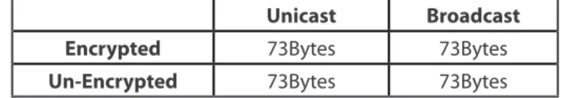
5.2. Maximum payloads
Depending on the way of transmission, a maximum data payload is defined:
Unicast Broadcast
Encrypted 73Bytes 73Bytes
Un-Encrypted 73Bytes 73Bytes
Power Gain and Sensibility
6. Power Gain and Sensibility
When configuring a node and a network, one important parameter is related with power gain and sensibility.
6.1. Power Level
Power level(dBm) at which the RF module transmits conducted power.
This command is only valid using XBee 802.15.4, not in XBee 900MHz. XBee 802.15.4 are divided in Normal model and PRO model. Its possible values are:
Parameter XBee XBee-PRO XBee-PRO International
0 -10dBm 10dBm PL=4 : 10dBm
1 -6dBm 12dBm PL=3 : 8dBm
2 -4dBm 14dBm PL=2 : 2dBm
3 -2dBm 16dBm PL=1 : -3dBm
4 0dBm 18dBm PL=0 : -3dBm
Figure 7: Power Output Level on XBee Series I module
NOTE: dBm is a standard unit to measure power level taking as reference a 1mW signal. Values expressed in dBm can be easily converted to mW using the next formula:
mW = 10^(value dBm/10) Graphics about transmission power are exposed next:
0,1 0,25 0,4 0,63 1 -12 -10 -8 -6 -4 -2 0
XBee Output Power Level
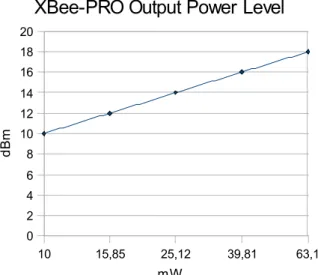
mW dBm 10 15,85 25,12 39,81 63,1 0 2 4 6 8 10 12 14 16 18 20
XBee-PRO Output Power Level
mW
dBm
Example of use
{
xbeeDM.setPowerLevel(0); // Set Power Output Level to the minimum value xbeeDM.getPowerLevel(); // Get Power Output Level
}
Related Variables
xbeeDM.powerLevel → stores the power output level selected
Power Gain and Sensibility
6.2. Received Signal Strength Indicator
It reports the Received Signal Strength of the last received RF data packet. It only indicates the signal strength of the last hop, so it does not provide an accurate quality measurement of a multihop link.
Example of use:
{
xbeeDM.getRSSI(); // Get the Receive Signal Strength Indicator }
Related Variables
xbeeDM.valueRSSI→ stores the RSSI of the last received packet
The ideal working mode is getting maximum coverage with the minimum power level. Thereby, a compromise between power level and coverage appears. Each application scenario will need some tests to find the best combination of both parameters.
Connectivity
7. Connectivity
7.1. Topologies
DigiMesh provides different topologies to create a network:
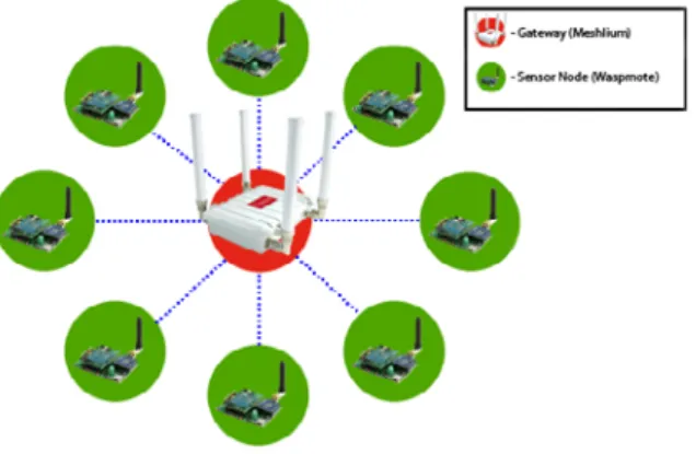
• Star: a star network has a central node, which is linked to all other nodes in the network. The central node gathers all data coming from the network nodes.
Figure 10: Star Topology
• Mesh: all the nodes are connected among them. DigiMesh provides a Network Layer to route packets among nodes out of sight.
Figure 11: Mesh Topology
7.2. DigiMesh Architecture
Mesh networking allows messages routing through several different nodes to a final destination. In the event that one RF connection between nodes is lost (due to power-loss, environmental obstructions, etc.) critical data can still reach its destination due to the mesh networking capabilities embedded inside the modules.
DigiMesh contains the following features
• Self-healing: any node may enter or leave the network at any time without causing the network as a whole to fail.
• Peer-to-peer architecture: no hierarchy and no parent-child relationships are needed.
• Quiet Protocol: routing overhead will be reduced by using a reactive protocol similar to AODV.
• Route Discovery: rather than maintaining a network map, routes will be discovered and created only when needed.
• Selective acknowledgments: only the destination node will reply to route requests.
• Reliable delivery: reliable delivery of data is accomplished by means of acknowledgements.
Connectivity
7.2.1. Routing
A module within a mesh network is able to determine reliable routes using a routing algorithm and table. The routing algorithm uses a reactive method derived from AODV (Ad-hoc On-demand Distance Vector). An associative routing table is used to map a destination node address with its next hop. By sending a message to the next hop address, either the message will reach its destination or be forwarded to an intermediate node which will route the message on to its destination. A message with a Broadcast address is broadcast to all neighbors. All receiving neighbors will rebroadcast the message and eventually the message will reach all corners of the network. Packet tracking prevents a node from resending a broadcast message twice.
7.2.2. Route Discovery Process
If the source node doesn’t have a route to the requested destination, the packet is queued to await a route discovery (RD) process. This process is also used when a route fails. A route fails when the source node uses up its network retries without ever receiving an ACK. This results in the source node initiating RD.
RD begins by the source node broadcasting a route request (RREQ). Any node that receives the RREQ that is not the ultimate destination is called an intermediate node. Intermediate nodes may either drop or forward an RREQ, depending on whether the new RREQ has a better route back to the source node. If so, information from the RREQ is saved and the RREQ is updated and broadcast. When the ultimate destination receives the RREQ, it unicasts a route reply (RREP) back to the source node along the path of the RREQ. This is done regardless of route quality and regardless of how many times an RREQ has been seen before. This allows the source node to receive multiple route replies. The source node selects the route with the best round trip route quality, which it will use for the queued packet and for subsequent packets with the same destination address.
7.3. Connections
Every RF data packet sent over-the-air contains a Source Address and Destination Address field in its header. DigiMesh supports long 64-bit addresses. A unique 64-bit IEEE source address is assigned at the factory and can be read with the functions explained in chapter 3.
DigiMesh supports Unicast and Broadcast transmission.
7.3.1. Unicast
When transmitting in Unicast communications, reliable delivery of data is accomplished using retries and acknowledgements. The number of retries is determined by the Network Retries (NR) parameter (explained in chapter 4). RF data packets are sent up to NR + 1 times and ACKs (acknowledgements) are transmitted by the receiving node upon receipt. If a network ACK is not received within the time it would take for a packet to traverse the network twice, a retransmission occurs.
7.3.2. Broadcast
Broadcast transmissions will be received and repeated by all nodes in the network. Because ACKs are not used the originating node will send the broadcast four times. Essentially the extra transmissions become automatic retries without acknowledgments. This will result in all nodes repeating the transmission four times as well. In order to avoid RF packet collisions, a random delay is inserted before each node relays the broadcast message. This time is specified by Network Delay Slots, explained in chapter 4.
7.4. Sending Data
Sending data is a complex process which needs some special structures and functions to carry out. Due to the limit on maximum payloads (see chapter 5) it is usual the packet fragmentation, so an application header has been created to deal with this process. This application header is sent inside RF Data, following the API Frame Structure.
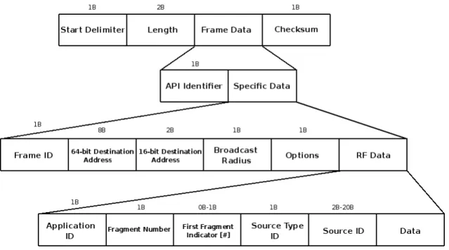
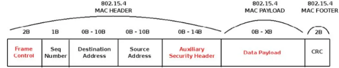
7.4.1. API Frame Structure
The structure used to transmit packets via RF is specified by the used modules. The application header has been added to that defined structured as shown below:
Connectivity
Figure 12: 64-bit API Frame Structure
7.4.2. Application Header
This application header is filled by the transmitter (internal Waspmote operation) and it is used by the receiver to treat the packet or fragment. It is sent in data field, so the maximum payload is reduced in a variable length (depending on the source ID type chosen).
Figure 13: Data field in an API frame
To add some application level features to the receiver, some fields have been added like ID or Source ID. Source ID identifies the origin node which created the packet. It is useful in multi-hops networks, to identify the origin node to answer. To identify this node, three ID can be chosen:
• MAC Address: 64-bit MAC Source Address
• Network Address: 16-bit Network Address
• Node Identifier: 20-byte max string NI
The different fields of this header and its structure inside the data field used in an API frame is represented in figure 13
• ID: specifies the ID at application level. It allows to identify the packet among various packets in the receiver.
• Frag Num: specifies the position of the fragment in its packet. The first fragment shows the total number of fragments of the packet.
• [#]: optional field that is included in the first fragment to indicate it is the first fragment.
• Source Type: specifies the source ID type chosen. The possibilities are MAC, 16-bit or NI.
• Source ID: specifies the source ID of the origin node. It is related with the previous field.
Connectivity
7.4.3. Fragmentation
When the data length of a packet exceeds the maximum payload, the packet has to be fragmented to reach the destination. If the packet is not fragmented, the module will discard it without even transmitting the packet.
NOTE: Due to restricted memory in Waspmote, the maximum recommended data in a packet is 1500 Bytes (to be fragmented).
7.4.4. Structure packetXBee
It is the structure used for the packet to send. It was explained in chapter 5. The process to send a packet is explained next:
1. A structure ‘packetXBee’ is created to contain the packet to send.
2. That structure is filled with the correct data into the corresponding fields.
3. The API function responsible of sending data is called, using the previously created structure as the input. The API function takes care of the rest of the process, returning the process successful or failure.
7.4.5. Sending without API header
There is a function to send raw data without the API header. This mode has been designed to send simple data to a gateway when the API features are not necessary.
Broadcast and Unicast transmissions are supported, as well as encryption.
7.4.6. Examples
To simplify the examples and make them easy to read, there are some lines doesn’t work exactly in C/C++
• Sending a packet of 50 bytes without API header.
{
char* data;
for(int c=0;c<50;c++) // Set the data
{
data[c]=’A’;
}
xbeeDM.send(“0013A2004030F66A”,data); }
• Sending a packet of 50 bytes. Unicast 64-bit Mode. 16-bit NA Source ID.
{
packetXBee* paq_sent; // create packet to send char* data;
paq_sent->mode=UNICAST; // set Unicast mode
paq_sent->packetID=0x52; // set ID application level paq_sent->opt=0x00; // set options. No option selected. for(int c=0;c<50;c++) // Set the data
{
data[c]=’A’;
}
xbeeDM.setOriginParams(paq_sent, “1221”, MY_TYPE); // sets Origin Parameters
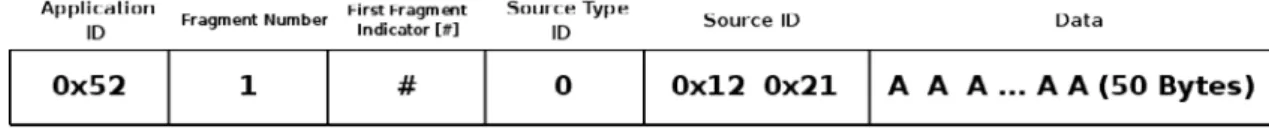
xbeeDM.setDestinationParams(paq_sent, “0013A2004030F686”, data, MAC_TYPE, DATA_ABSOLUTE); state=xbeeDM.sendXBee(paq_sent); // Call function responsible to send data
Connectivity
The data field in the API frame generated by the function ‘sendXBee’ will be:
Figure 14: API Application Header
• Sending a 50-bytes packet. Unicast 64-bit Mode. 64-bit MAC Source ID.
{
packetXBee* paq_sent; // create packet to send char* data;
paq_sent->mode=UNICAST; // set Unicast mode
paq_sent->packetID=0x52; // set ID application level paq_sent->opt=0x00; // set options. No option selected. for(int c=0;c<50;c++) // Set the data
{
data[c]=’A’;
}
xbeeDM.setOriginParams(paq_sent, “0013A2004030F66A”, MAC_TYPE);
xbeeDM.setDestinationParams(paq_sent, “0013A2004030F686”, data, MAC_TYPE, DATA_ABSOLUTE); state=xbeeDM.sendXBee(paq_sent); // Call function responsible to send data
}
The data field in the API frame generated by the function ‘sendXBee’ will be:
Figure 15: API Application Header
• Sending a 50-bytes packet. Broadcast Mode. Node Identifier Source ID Type.
{
packetXBee* paq_sent; // create packet to send char* data;
paq_sent->mode=BROADCAST; // set Broadcast mode
paq_sent->packetID=0x52; // set ID application level paq_sent->opt=0x00; // set options. No option selected. for(int c=0;c<50;c++) // Set the data
{
data[c]=’A’;
}
xbeeDM.setOriginParams(paq_sent, “forrestNode-01”, NI_TYPE);
xbeeDM.setDestinationParams(paq_sent, “000000000000FFFF”, data, MAC_TYPE, DATA_ABSOLUTE); state=xbeeDM.sendXBee(paq_sent); // Call function responsible to send data
}
The data field in the API frame generated by the function ‘sendXBee’ will be:
Connectivity
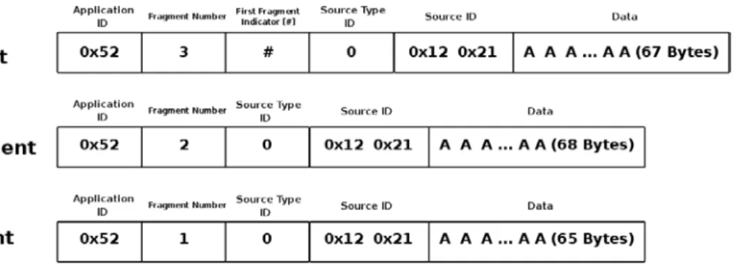
• Sending a 200-bytes packet. Unicast 64-bit Mode. 16-bit Source ID Type.
{
packetXBee* paq_sent; // create packet to send char* data;
paq_sent->mode=UNICAST; // set Broadcast mode
paq_sent->packetID=0x52; // set ID application level paq_sent->opt=0x00; // set options. No option selected. for(int c=0;c<200;c++) // Set the data
{
data[c]=’A’;
}
xbeeDM.setOriginParams(paq_sent, “1221”, MY_TYPE);
xbeeDM.setDestinationParams(paq_sent, “0013A2004030F686”, data, MAC_TYPE, DATA_ABSOLUTE); state=xbeeDM.sendXBee(paq_sent); // Call function responsible to send data
}
Due to the amount of data, the packet needs to be fragmented before being sent. The maximum data payload is 73Bytes (see chapter 5) and the application header will occupy a maximum of 6 Bytes (in the first fragment), so there will be three fragments, sending 67Bytes (data) in the first fragment, 68Bytes (data) in the second fragment and 65Bytes (data) in the third fragment.
Figure 17: API Application Header
7.5. Receiving Data
Receiving data is a complex process which needs some special structures to carry out. These operations are transparent to the API user, so it is going to be explained the necessary information to be able to read properly a received packet.
Before any packet has been received, a multidimensional array of ‘matrix’ structures pointers, an array of ‘index’ structures pointers and an array of ‘packetXBee’ structures pointers are created. The size of these arrays is defined by some constants in compilation time, so it is necessary to adequate its value to each scenario before compile the code:
• MAX_FINISH_PACKETS: max number of finished packets pending of treatment. It specifies the size of the array of finished packets.
• MAX_FRAG_PACKETS: max number of fragments per packet. It specifies the number of columns in the multidimensional array of pending fragments. The number of rows is specified by MAX_FINISH_PACKETS.
When a packet or fragment is received, the algorithm used in reception API function is:
1. Check if the fragment is a new packet or belongs to an existing packet. If it is a new packet, an structure ‘index’ is created and linked to the array index previously created. The application level information is stored in that structure. If it belongs to an existing packet, it doesn’t store any information.
2. Create an structure ‘matrix’ and link it to the corresponding position in the multidimensional matrix array. The position is calculated basing on the information stored in the ‘index’ array.
Connectivity
4. Check if the packet is complete. If the packet is complete, a ‘packetXBee’ structure is created and linked to the corresponding position in the array of finished packets. The different fragments are ordered and copied to this structure, as the application level information. The ‘index’ and row of ‘matrix’ are released, to free memory. If the packet is not complete, goes to next step. 5. Exit the function.
When a packet is received via RF, the module will send the data via UART, so it is recommended to check periodically if data is available. The API function responsible of reading packets can read more than one fragment, but the XBee module may overflow its buffer, so it is recommended to read packets one by one.
When a packet is completed, it will be stored in a finished packets array called ‘packet_finished’. This array should be used by the application to read the received packet. A variable called ‘pos’ is used to know if there are pending received packets: if ‘pos’=0, there is no packet available; if ‘pos’>0, there will be as many pending packets as its value (pos=3, 3 pending packets).
7.5.1. Examples
• Received 50-bytes data packet. Unicast. 16-bit NA Source ID Type
{
state=xbeeDM.treatData(); // Read a packet when XBee has noticed it to us if( xbeeDM.pos>0 )
{
/* Available info: (there are more available information) */ network_address[0]=packet_finished[xbeeDM.pos-1]->naS[0]; network_address[1]=packet_finished[xbeeDM.pos-1]->naS[1]; }
}
Available Information
packet_finished[xbeeDM.pos-1]->naS: stores the 16-bit network address of the sender. packet_finished[xbeeDM.pos-1]->macSH: stores the 32 upper bits of MAC sender address. packet_finished[xbeeDM.pos-1]->macSL: stores the 32 lower bits of MAC sender address. packet_finished[xbeeDM.pos-1]->naO: stores the 16-bit network address of the origin sender. packet_finished[xbeeDM.pos-1]->mode: stores the transmission mode. Unicast in this case. packet_finished[xbeeDM.pos-1]->data: stores the data received. Max size ‘MAX_DATA’.
packet_finished[xbeeDM.pos-1]->packetID: stores the packet ID of the received message. 0x52 in this case. packet_finished[xbeeDM.pos-1]->typeSourceID: stores the source type ID used in the message.
After receiving the packet, due to there is only one fragment, it will be completed, so variable ‘pos’ will be greater than zero. This variable is used to index the array where the received packet is stored. The information that has been stored is indicated in the example.
• Received 50-bytes data packet. Unicast. 64-bit MAC Address Source ID Type
{
state=xbeeDM.treatData(); // Read a packet when XBee has noticed it to us if( xbeeDM.pos>0 )
{
/* Available info: (there are more available information) */ source_address[0]=packet_finished[xbeeDM.pos-1]->macSH[0];
...
source_address[3]=packet_finished[xbeeDM.pos-1]->macSH[3]; }
Connectivity
Available Information
packet_finished[xbeeDM.pos-1]->naS: stores the 16-bit network address of the sender. packet_finished[xbeeDM.pos-1]->macSH: stores the 32 upper bits of MAC sender address. packet_finished[xbeeDM.pos-1]->macSL: stores the 32 lower bits of MAC sender address. packet_finished[xbeeDM.pos-1]->macOH: stores the 32 upper bits of MAC origin sender address. packet_finished[xbeeDM.pos-1]->macOL: stores the 32 lower bits of MAC origin sender address. packet_finished[xbeeDM.pos-1]->mode: stores the transmission mode. Unicast in this case. packet_finished[xbeeDM.pos-1]->data: stores the data received. Max size ‘MAX_DATA’.
packet_finished[xbeeDM.pos-1]->packetID: stores the packet ID of the received message. 0x52 in this case. packet_finished[xbeeDM.pos-1]->typeSourceID: stores the source type ID used in the message.
After receiving the packet, due to there is only one fragment, it will be completed, so variable ‘pos’ will be greater than zero. This variable is used to index the array where the received packet is stored. The information that has been stored is indicated in the example.
• Received 50-bytes data packet. Broadcast. Node Identifier Source ID Type
{
state=xbeeDM.treatData(); // Read a packet when XBee has noticed it to us if( xbeeDM.pos>0 )
{
/* Available info: (there are more available information) */ source_address[0]=packet_finished[xbeeDM.pos-1]->macSH[0]; ... source_address[3]=packet_finished[xbeeDM.pos-1]->macSH[3]; } } Available Information
packet_finished[xbeeDM .pos-1]->naS: stores the 16-bit network address of the sender. packet_finished[xbeeDM.pos-1]->macSH: stores the 32 upper bits of MAC sender address. packet_finished[xbeeDM.pos-1]->macSL: stores the 32 lower bits of MAC sender address.
packet_finished[xbeeDM.pos-1]->niO: stores 20-byte max string used to Node Identifier of the origin sender packet_finished[xbeeDM.pos-1]->mode: stores the transmission mode. Unicast in this case.
packet_finished[xbeeDM.pos-1]->data: stores the data received. Max size ‘MAX_DATA’.
packet_finished[xbeeDM.pos-1]->packetID: stores the packet ID of the received message. 0x52 in this case. packet_finished[xbeeDM.pos-1]->typeSourceID: stores the source type ID used in the message.
After receiving the packet, due to there is only one fragment, it will be completed, so variable ‘pos’ will be greater than zero. This variable is used to index the array where the received packet is stored. The information that has been stored is indicated in the example.
• Received 200-bytes data packet. Unicast. 16-bit NA Source ID Type
{
state=xbeeDM.treatData(); // Read a packet when XBee has noticed it to us if( xbeeDM.pos>0 )
{
/* Available info: (there are more available information) */ network_address[0]=packet_finished[xbeeDM.pos-1]->naS[0]; network_address[1]=packet_finished[xbeeDM.pos-1]->naS[1]; }
Connectivity
Available Information
packet_finished[xbeeDM .pos-1]->naS: stores the 16-bit network address of the sender. packet_finished[xbeeDM.pos-1]->macSH: stores the 32 upper bits of MAC sender address. packet_finished[xbeeDM.pos-1]->macSL: stores the 32 lower bits of MAC sender address. packet_finished[xbeeDM.pos-1]->naO: stores the 16-bit network address of the origin sender. packet_finished[xbeeDM.pos-1]->mode: stores the transmission mode. Unicast in this case. packet_finished[xbeeDM.pos-1]->data: stores the data received. Max size ‘MAX_DATA’.
packet_finished[xbeeDM.pos-1]->packetID: stores the packet ID of the received message. 0x52 in this case. packet_finished[xbeeDM.pos-1]->typeSourceID: stores the source type ID used in the message.
After receiving the first packet, due to there are three fragments, it will not be completed, so variable ‘pos’ will be zero. It is recommended to set a delay in the transmitter so as to the receiver doesn’t receive more than one packet at once. When the three fragments have been received, variable ‘pos’ will change its value and the information in the ‘packet_finished’ array will be available.
NOTE: Due to memory restrictions, it is recommended when a pending packet is treated and it is not necessary to store it any more, to release this pointer. If don’t, memory may overflow and crash the application. It is not possible having in a receiver node more than 1500Bytes. It is referred to a single big packet or many smaller packets in parallel.
7.6. Discovering and Searching Nodes
As explained in chapter 4, an extra Digi header enables some features discovering and searching nodes.
7.6.1. Structure used in Discovery
Discovering nodes is used to discover and report all modules on its current operating channel and PAN ID.
To store the reported information by other nodes, an structure called ‘Node’ has been created. This structure has the next fields:
uint8_t MY[2]; // 16b Network Address uint8_t SH[4]; // 32b Lower Mac Source uint8_t SL[4]; // 32b Higher Mac Source char NI[20]; // Node Identifier
uint8_t PMY[2]; // Parent 16b Network Address
uint8_t DT; // Device Type: 0=End 1=Router 2=Coord uint8_t ST; // Status: Reserved
uint8_t PID[2]; // Profile ID uint8_t MID[2]; // Manufacturer ID
uint8_t RSSI; // Receive Signal Strength Indicator
• MY
16-bit Network Address of the reported module.
• SH & SL
64-bit MAC Source Address of the reported module.
• NI
Node Identifier of the reported module
• PMY
Parent 16-bit network address. It specifies the 16-bit network address of its parent.
• DT
Device Type. It specifies if the node is a Coordinator, Router or End Device.
• ST
Connectivity
• PID
Profile ID. Profile ID used to application layer addressing.
• MID
Manufacturer ID. ID set by the manufacturer to identify the module.
• RSSI
Not returned in DigiMesh.
To store the found brothers, an array called ‘scannedBrothers’ has been created. It is an array of structures ‘Node’. To specify the maximum number of found brothers, it is defined a constant called ‘MAX_BROTHERS’. It is also defined a variable called ‘totalScannedBrothers’ that indicates the number of brothers have been discovered. Using this variable as index in the ‘scannedBrothers’ array, it will be possible to read the information about each node discovered.
Example of use:
{
xbeeDM.scanNetwork(); // Discovery nodes }
Related variables
xbeeDM.totalScannedBrothers → stores the number of brothers have been discovered.
xbeeDM.scannedBrothers → ‘Node’ structure array that stores in each position the info related to each found node. For example, xbeeDM.scannedBrothers[0].MY should store the 16-bit Network Address of the first found node.
7.6.2. Searching specific nodes
Another possibility for discovering a node is searching for a specific one. This search is based on using the Node Identifier. The NI of the node to discover is used as the input in the API function responsible of this purpose.
Example of use
{
packetXBee* paq_sent;
xbeeDM.nodeSearch(“forrestNode-01”,14,paq_sent); // ‘14’ is string length }
Related variables
paq_sent → Stores the 16-bit and 64-bit addresses of the searched. For example
paq_sent->MY[0] & paq_sent->MY[1] → stores the 16-bit NA of the searched node.
7.6.3. Node discovery to a specific node
When executing a Node Discovery all the nodes respond to it. If its Node Identifier is known, a Node Discovery using its NI as an input can be executed.
Example of use
{
xbeeDM.scanNetwork(“forrestNode-01”); // Performs a ND to that specific node }
Related variables
xbeeDM.totalScannedBrothers → stores the number of brothers have been discovered. In this case its value will be ‘1’ xbeeDM.scannedBrothers → Node’ structure array that stores in each position the info related to each found
Starting a Network
8. Starting a Network
To create a network only two parameters are necessary: channel and PAN ID. These parameters are the base of a network and we need to be careful choosing them. There are more parameters used to create a network like security parameters, which are not necessary but recommended (see chapter 12).
Two nodes are in the same network if they are using the same channel and PAN ID.
8.1. Choosing a channel
As explained in chapter 4, there are different channels to choose. In XBee Series 1, a random value between ‘0x0B’-’0x1A’ (XBee-PRO values are 0x0C-0x17) should be chosen. However, if XBee 900 is used, a random value between ‘0x01’-’0x0C’ should be chosen. This value will be used as the input parameter in the API function responsible of setting the channel.
Example of use
{
xbeeDM.setChannel(0x0C); // Set channel }
8.2. Choosing a PAN ID
A network must have an unique PAN ID. This PAN ID is a 16-bit number which values are comprised among 0-0xFFFF.
To set a valid PAN ID it is necessary to select a random number and use the API function responsible of setting this parameter. Any value comprised between 0-0xFFFF could be valid, but it should be used only by one network to avoid conflicts between them. Example of use
{
PANID={0x33,0x31}; // array containing the PAN ID xbeeDM.setPAN(PANID); // Set PANID
}
NOTE: If two different networks are using the same PAN ID, it doesn’t mean there will be interferences between them. Interferences will appear if both networks are transmitting in the same channel. If that happens, it will mean the two different networks will become the same network because both are using same PAN ID and channel frequency.
Joining an Existing Network
9. Joining an Existing Network
Joining an existing network process requires some knowledge about the network to join. Three parameters are needed: channel, PAN ID and security (explained in chapter 12).
9.1. Network parameters are known
When these three parameters are known, the process is reduced to set the parameters in the node.
9.1.1. Channel
To set channel, use the API function responsible of that matter. Example of use
{
xbeeDM.setChannel(0x0C); // Set Channel the network is working on }
9.1.2. PAN ID
To set PAN ID, use the API function responsible of that matter. Example of use
{
PANID={0x33,0x31}; // array containing PAN ID the network is using xbeeDM.setPAN(PANID); // Set PANID
}
Once these two parameters are set in the node, it will be part of the network, receiving messages from other nodes.
9.2. Network parameters are unknown
If channel or PANID are not known, it is not possible to join a DigiMesh network. The unique solution if channel is not known is launching ND in all the channels waiting for an answer, selecting the channel where it occurs.
9.3. Node Discovery
Once these parameters have been set, the node is part of the network, so now we can discover other nodes in the network. Some parameters are involved in a node discovery process.
9.3.1. Node Discovery Function
Performs a node discovery returning the found brothers in the network stored in an array of structures that contain information about the nodes as explained in chapter 7
Example of use:
{
xbeeDM.scanNetwork(); // Discovery nodes if(xbeeDM.totalScannedBrothers>0)
{
/* Available info (There are more available information) */ network_address[0]=scannedBrothers[totalScannedBrothers-1].MY[0]; network_address[1]=scannedBrothers[totalScannedBrothers-1].MY[1]; }
Joining an Existing Network
Available Information
scannedBrothers[totalScannedBrothers-1].MY → stores 16-bit NA of each module scannedBrothers[totalScannedBrothers-1].SH → stores the 32 upper bits of MAC address scannedBrothers[totalScannedBrothers-1].SL → stores the 32 lower bits of MAC address scannedBrothers[totalScannedBrothers-1].NI →stores the Node Identifier
scannedBrothers[totalScannedBrothers-1].PMY → stores the 16-bit NA of its parent scannedBrothers[totalScannedBrothers-1].DT→ stores the device type(C, R or E) scannedBrothers[totalScannedBrothers-1].ST → stores the status. Reserved by module. scannedBrothers[totalScannedBrothers-1].MID→ stores the 16-bit manufacturer ID scannedBrothers[totalScannedBrothers-1].PID → stores the 16-bit Profile ID
9.3.2. Node Discovery Time
It is the amount of time a node will wait for responses from other nodes when performing a ND. Example of use:
{
uint8_t time[2]={0x19,0x00};// In DigiMesh is only used first array position xbeeDM.setScanningTime(time); // Set Scanning Time in ND
xbeeDM.getScanningTime(); // Get Scanning Time in ND }
Available Information
Sleep Options
10. Sleep Options
10.1. Sleep Modes
All the nodes in a DigiMesh network can sleep, entering in a low power consumption mode.
There are several sleep modes characterized as either asynchronous or synchronous. Asynchronous sleeping modes should not be used in a synchronous sleeping network, and vice versa.
10.1.1. Asynchronous Cyclic Sleep
Asynchronous sleep modes can be used to control the sleep state on a module by module basis. Modules operating in an asynchronous sleep mode should not be used to route data.
10.1.2. Synchronous Cyclic Sleep
A node in synchronous cyclic sleep mode sleeps for a programmed time, wakes up in unison with other nodes, exchanges data and synchronization messages, and then returns to sleep. All synchronized cyclic sleep nodes enter and exit a low power state at the same time. This forms a cyclic sleeping network. While asleep, it cannot receive RF messages, neither will it read commands from the UART port.
10.2. Sleep Parameters
There are some parameters involved in setting a node to sleep.
10.2.1. Sleep Mode
Sets the sleep mode for a module. Its available values are:
• 0: Normal Mode. The node will not sleep. Normal mode modules are not compatible with nodes configured for sleep. Excepting the case of adding a new node to a sleep-compatible network, a network should consist of either only normal nodes or only sleep-compatible nodes.
• 1: Asynchronous Pin Sleep Mode: Pin sleep allows the module to sleep and wake according to the state of the Sleep_RQ pin (pin 9). When Sleep_RQ is set high, the module will finish any transmit or receive operations and enter a low-power state. The module will wake from pin sleep when the Sleep_RQ pin is set low.
• 4: Asynchronous cyclic sleep. In this mode, the module periodically sleeps and wakes based on the SP and ST commands.
• 5: Asynchronous cyclic sleep with pin wake-up. In this mode, the module acts in the same way as asynchronous cyclic sleep with the exception that the module will prematurely terminate a sleep period when a falling edge of the SLEEP_RQ line is detected.
• 7: Synchronous Sleep Support Mode. The node will synchronize itself with a sleeping network but will not sleep . They are especially useful when used as preferred sleep coordinator nodes and as aids in adding new nodes to a sleeping network.
• 8: Synchronous Cyclic Sleep Mode. The node sleeps for a programmed time, wakes in unison with other nodes, exchanges data and sync messages, and then returns to sleep.
Example of use:
{
xbeeDM.setSleepMode(8); // Set Sync Cyclic Sleep Mode xbeeDM.getSleepMode(); // Get the Sleep Mode used }
Related Variables
Sleep Options
10.2.2. Sleep Period
It determines how long a node will sleep per period, with a maximum 4 hours. In the parent, it determines how long it will buffer a message for the sleeping device. Time in units of 10ms represented in hexadecimal.
Example of use:
{
uint8_t asleep[3]={0x15,0xF9,0x00};
xbeeDM.setSleepTime(asleep); // Set Sleep period to 4 hours }
Related Variables
xbeeDM.sleepTime → stores the sleep period the module will be sleeping
10.2.3. Time Before Sleep
It determines the time a module will be awake waiting before sleeping. It resets each time data is received via RF or serial. Once the timer expires, the device will enter low-power state. Time in units of ms represented in hexadecimal.
Example of use:
{
uint8_t awake[3]={0x36,0xEE,0x80};
xbeeDM.setAwakeTime(awake); // Set time the module remains awake: 1hour }
Related Variables
xbeeDM.awakeTime → stores the time the module remains awake
10.2.4. Sleep Options
It configures options for sleeping modes. Possible values are read as a bitmask (Bit 0 and Bit 1 cannot be set at the same time). For synchronous sleep modules, the following sleep options are defined:
• bit 0: Preferred sleep coordinator. The node always acts as sleep coordinator
• bit 1: Non-sleep coordinator. Node never acts as a sleep coordinator
• bit 2: Enable API sleep status messages
• bit 3: Disable early wake-up for missed synchronizations
• bit 4: Enable node type equality
• bit 5: Disable coordinator rapid synchronization deployment mode. For asynchronous sleep modules, the following sleep options are defined:
• bit 8: Always wake for ST time Example of use:
{
xbeeDM.setSleepOptions(0x01); // Set the node to be the preferred sleep coordinator }
Related Variables
Sleep Options
10.2.5. Sleep Status
It queries a number of Boolean values describing the status of the module. Possible values are read as a bitmask:
• Bit 0: If it is true, the network is in its wake state
• Bit 1: If it is true, the node is currently acting as a network sleep coordinator
• Bit 2: If it is true, the node has ever received a valid sync message
• Bit 3: If it is true, the node has received a sync message in the current wake cycle
• Bit 4: If it is true, the user has altered the sleep settings on the module so that the node will nominate itself and send a sync message with the new settings at the beginning of the next wake cycle
• Bit 5: This bit will be true if the user has requested that the node nominate itself as the sleep coordinator (using the commissioning button or the CB2 command).
• bit 6: This bit will be true if the node is currently in deployment mode.
• All other bits: Reserved - All non-documented bits can be any value and should be ignored. Example of use:
{
xbeeDM.getSleepStatus(); }
Related Variables
xbeeDM.sleepStatus → stores the sleep status of the module
10.2.6. Missed synchronizations count
It determines the number of syncs that have been missed. This value can be reset to 0. When the value reaches 0xFFFF it will not be incremented anymore. Example of use: { xbeeDM.getMissedSyncCount(); } Related Variables
xbeeDM.missedSyncs → stores the missed synchronizations
10.2.7. Operational sleep period
It determines the sleep period that the node is currently using. This number will oftentimes be different from the SP parameter if the node has synchronized with a sleeping router network.
Example of use:
{
xbeeDM.getOpSleepPeriod(); }
Related Variables
Sleep Options
10.2.8. Operational wake period
It determines the wake period that the node is currently using. This number will oftentimes be different from the ST parameter if the node has synchronized with a sleeping router network.
Example of use:
{
xbeeDM.getOpWakePeriod(); }
Related Variables
xbeeDM.opWakePeriod → stores the current wake period
10.3. ON/OFF Modes
In addition to the XBee sleep modes, Waspmote provides the feature of controlling the power state with a digital switch. This means that using one function included in the Waspmote API, any XBee module can be powered up or down (0uA).
Example of use:
{
Xbee.setMode(XBEE_ON); // Powers XBee up XBee.setMode(XBEE_OFF); // Powers XBee down }