PETERROB• CARLOSCORONEL
DESIGN, IMPLEMENTATION, AND MANAGEMENT
ALL RIGHTS RESERVED. No part of this work covered by the copyright hereon may be reproduced or used in any form or by any means—graphic, electronic, or mechanical,
DO NOT
P
review
Object-oriented (OO) technology draws its strength from powerful programming and modeling techniques and advanced data-handling capabilities. Because OO technology has become an important contributor to the evolution of database systems, this appendix explores the characteristics of OO systems and how those characteristics affect data modeling and design. This appendix also investigates how, through the creation of what are known as extended relational or object/relational databases, relational database vendors have responded to the demand for databases capable of handling increasingly complex data types. You will see how some of those features are implemented in Oracle.
G
APPENDIX
DO NOT
G.1 OBJECT ORIENTATION AND ITS BENEFITS
Object orientation is a modeling and development methodology based on object-oriented (OO) concepts. More precisely, object orientation is defined as a set of design and development principles based on conceptually autonomous computer structures known as objects. Each object represents a real-world entity with the ability to act upon itself and to interact with other objects.
Considering that definition, it does not require much imagination to see that using objects makes modularity almost inevitable. Object orientation concepts have been widely applied to many computer-related disciplines, especially those involving complex programming and design problems. Table G.1 summarizes some object orientation contributions to computer-related disciplines.
TABLE
G.1
Object Orientation Contributions
COMPUTER-RELATED AREA OO CONTRIBUTIONS
Programming languages Reduces the number of lines of code Decreases development time Enhances code reusability Makes code maintenance easier Enhances programmer productivity
Graphical user interfaces (GUIs) Enhances ability to create easy-to-use interfaces Improves system end-user friendliness
Makes it easy to define standards Databases Supports abstract data types
Supports complex objects Supports multimedia data types
Design Captures more of the data model’s semantics Represents the real world more accurately
Supports complex data manipulations in specialized applications that target graphics, imaging, mapping, financial modeling, tele-communications, geospatial applications, medical applications, and so on
Operating systems Enhances system portability by creating layers of abstractions to handle hardware-specific issues
Facilitates system extensibility through the use of inheritance and other object-oriented constructs
G.2 THE EVOLUTION OF OBJECT-ORIENTED CONCEPTS
Object-oriented concepts stem fromobject-oriented programming(OOP), which was developed as an alternative to traditional programming methods. In an OOP environment, the programmer creates or uses objects (self-contained, reusable modules that contain data as well as the procedures used to operate on the data).
OO concepts first appeared in programming languages such as Ada, ALGOL, LISP, and SIMULA. Those program-ming languages set the stage for the introduction of more refined OO concepts. Smalltalk, C++, and Java are popular
object-oriented programming languages (OOPLs). Java is used to create Web applications that run on the Internet and are independent of operating systems.
OOPLs were developed to:
쐌 Provide an easy-to-use software development environment.
쐌 Provide a powerful software modeling tool for application development.
DO NOT
쐌 Decrease development time by reducing the amount of code.
쐌 Improve programmer productivity by making the code reusable.
OOP changes not only the way in which programs are written, but also how those programs behave. In the object-oriented view of the world, each object can manipulate the data that is part of the object. In addition, each object can send messages to change the data of other objects. Consequently, the OO environment has several important attributes:
쐌 The data set is no longer passive.
쐌 Data and procedures are bound together, creating an object.
쐌 The object has an innate ability to act on itself.
An object can interact with other objects to create a system. Because such objects carry their own data and code, it becomes easier to produce reusable modular systems. It is precisely that characteristic that makes OO systems seem natural to those with little programming experience, but confusing to many whose traditional programming expertise has trained them to split data and procedures. It is not surprising that OO notions became more viable with the advent of personal computers because personal computers are typically operated by end users rather than by programmers and systems design specialists.
OO programming concepts have also had an effect on most computer-based activities, including those based on databases. Because a database is designed to capture data about a business system, it can be viewed as a set of interacting objects. Each object has certain characteristics (attributes) and has relationships with other objects (methods). Given that structure, OO systems have an intuitive appeal for those doing database design and development. As database designers rather than programmers, you cannot afford to ignore the OO revolution.
G.3 OBJECT-ORIENTED CONCEPTS
Although OO concepts have their roots in programming languages and the programmers among you will recognize basic programming elements, you do not need to know anything about programming to understand these concepts.
G.3.1 Objects: Components and Characteristics
In OO systems, everything you deal with is an object, whether it is a student, an invoice, an airplane, an employee, a service, a menu panel, or a report. Some objects are tangible, and some are not. Anobjectcan be defined as “an abstract representation of a real-world entity that has a unique identity, embedded properties, and the ability to interact with other objects and act upon itself.”
Note the difference between object and entity. An entity has data components and relationships, but lacks manipulative ability. Other differences will be identified later.
A defining characteristic of an object is its unique identity. To emphasize this point, let’s examine the real-world objects displayed in Figure G.1. As you examine those simple objects, note that the student named J. D. Wilson has a unique (biological) identity and therefore constitutes a different object from M. R. Gonzalez or V. K. Spelling. Note also that although they share commongeneralcharacteristics such as name, Social Security number, address, and date of birth, each object exists independently in time and space.
G.3.2 Object Identity
The object’s identity is represented by anobject ID(OID), which is unique to the object. The OID is assigned by the system at the moment of the object’s creation
DO NOT
and cannot be changed under any circumstances.Do not confuse the relational model’s primary key with an OID. In contrast to the OID, a primary key is based on user-givenvalues of selected attributes and can be changed at any time. The OID is assigned by the system, does not depend on the object’s attribute values, and cannot be changed.The OID can be deleted only when the object is deleted, and that OID cannot be reused.
G.3.3 Attributes (Instance Variables)
Objects are described by their attributes, known asinstance variables in an OO environment. For example, the student John D. Smith may have the attributes (instance variables) shown in Table G.2. Each attribute has a unique name and a data type associated with it. In Table G.2, the attribute names are SOCIAL_SECURITY_NUMBER, FIRST_NAME, MIDDLE_INITIAL, LAST_NAME, and so on. Traditional data types, also known asbase data types
orconventional data types, are used in most programming languages and include real, integer, string, and so on.
TABLE
G.2
Object Attributes
ATTRIBUTE NAME ATTRIBUTE VALUE
SOCIAL_SECURITY_NUMBER 414-48-0944 FIRST_NAME John MIDDLE_INITIAL D LAST_NAME Smith DATE_OF_BIRTH 11/23/1966 MAJOR * Accounting SEMESTER_GPA 2.89 OVERALL_GPA 3.01
COURSES_TAKEN * ENG201;MATH243;HIST201;ACCT211;ECON210;ECON212; ACCT212; CIS220;ENG202;MATH301;HIST202;CIS310; ACCT343;ACCT345; ENG242;MKTG301;FIN331;ACCT355
ADVISOR* Dr. W. R. Learned
* Represents an attribute that references one or more other objects
Attributes also have a domain. Thedomainlogically groups and describes the set of all possible values that an attribute can have. For example, the possible values of SEMESTER_GPA (see Table G.2) can be represented by the real number base data type. But that does not mean that any real number is a valid GPA. Keep in mind that base data types define base domains; that is, realrepresents all real numbers, integerrepresents all integers, date represents all possible dates,stringrepresents any combination of characters, and so on. However, base data type domains are the building
FIGURE
G.1
Real-world Student objects
Objects
J. D. Wilson M. R. Gonzalez V. K. Spelling
DO NOT
blocks used to construct more restrictivenameddomains at a higher logical level. For example, to define the domain for the GPA attribute precisely, a domain named “GPA” must be created. Every domain has a name and a description, including the base data type, size, format, and constraints for the domain’s values. Therefore, the “GPA” domain can be defined as “any positive number between 0.00 and 4.00 with only two decimal places.” In this case, there is a domain name “GPA,” a base data type “real,” a constraint rule “any positive number between 0.00 and 4.00,” and a format “with only two decimal places.” The “GPA” domain will provide the values for the SEMESTER_GPA and OVERALL_GPA attributes. Domains can also be defined as lists of possible values separated by commas. For example the “GENDER” domain can be defined as “Male, Female” or as “M, F.”
It is important to note that the relational database model also supports domains. In fact, C. J. Date, one of the relational database model’s “parents,” presents domains as the way in which relational systems are able to support abstract data types, thus providing the same functionality as object-oriented databases.1
Just as in the ER model, an object’s attribute can besingle-valuedormultivalued. Therefore, the object’s attribute can draw a single value or multiple values from its domain. For example, the SOCIAL_SECURITY_NUMBER attribute takes only one value from its domain because the student can have only one Social Security number. In contrast, an attribute such as LANGUAGE or HOBBY can have many values because a student might speak many languages or have many hobbies.
Object attributes may reference one or more other objects. For example, the attribute MAJOR refers to a Department object, the attribute COURSES_TAKEN refers to a list (or collection) of Course objects, and the attribute ADVISOR refers to a Professor object. At the implementation level, the OID of the referenced object is used to link both objects, thus allowing the implementation of relationships between two or more objects. Using the example in Table G.2, the MAJOR attribute contains the OID of a Department object (Accounting) and the ADVISOR attribute contains the OID of a Professor object (Dr. W. R. Learned). The COURSES_TAKEN attribute contains the OID of an object that contains a list of Course objects; such an object is known as acollection object.
G.3.4 Object State
Theobject stateis the set of values that the object’s attributes have at any given time. Although the object’s state can vary, its OID remains the same. If you want to change the object’s state, you must change the values of the object’s attributes. To change the object’s attribute values, you must send a message to the object. Thismessagewill invoke amethod.
G.3.5 Messages and Methods
Amethodis the code that performs a specific operation on the object’s data. Methods protect data from direct and unauthorized access by other objects. To help you understand messages and methods, imagine that the object is a nutshell. The nutshell’s nucleus (the nut) represents the object’s data structure, and the shell represents its methods. (See Figure G.2.)
Every operation performed on an object must be implemented by a method. Methods are used to change the object’s attribute values or to return the value of selected object attributes. Methods represent real-world actions, such as changing a student’s major, adding a student to a course, or printing a student’s name and address. In effect,methods
Note
Observe the difference between the relational and OO models at this point. In the relational model, a table’s attribute may contain only a value used to join rows in different tables. The OO model does not need such joins to relate objects to one another.
DO NOT
are the equivalent of procedures in traditional programming languages. In OO terms, methods represent the object’s behavior.
Every method is identified by anameand has abody. The body is composed of computer instructions written in some programming language to represent a real-world action. For example, using the object attributes described in Table G.2, you can define a methodAvegpathat will return the average GPA of a student by using the object’s attributes SEMESTER_GPA and OVERALL_GPA. Thus, the method namedAvegpamay be represented by the transformation shown in Figure G.3.
As you examine Figure G.3, note that the Return(xgpa) would yield (3.2 * 15) + (3.0 * 60)/(15 + 60) = (48 + 180)/75 = 3.04 for a student with the following characteristics:
쐌 Current semester GPA is 3.2.
FIGURE
G.2
Depiction of an object
Object X Method 1 Method 2 Method 3 Method 4 DataFIGURE
G.3
Method components
Xgpa = (SEMESTER_GPA*SEMESTER_HOURS+PREVIOUS_GPA*PREVIOUS_HOURS)/ (SEMESTER_HOURS+PREVIOUS_HOURS) Method Avegpa Xgpa = 0 Return(xgpa) (Method’s name)Instance variable names
(Returns the average GPA)
Method body
DO NOT
쐌 Current class load is 15 semester hours.
쐌 Previous GPA was 3.0 earned for a total of 60 hours.
As you examine that example, note that a method can access the instance variables (attributes) of the object for which the method is defined.
To invoke a method, you send a message to the object. Amessageis sent by specifying a receiver object, the name of the method, and any required parameters. The internal structure of the object cannot be accessed directly by the message sender, which is another object. Denial of access to the structure ensures the integrity of the object’s state and hides the object’s internal details. The ability to hide the object’s internal details (attributes and methods) is known as
encapsulation.
An object may also send messages to change or interrogate another object’s state. (Tointerrogatemeans to ask for the interrogated object’s instance variable value or values.) To perform such object-change and interrogation tasks, the method’s body can contain references to other objects’ methods (send messages to other objects), as depicted in Figure G.4.
G.3.6 Classes
OO systems classify objects according to their similarities and differences. Objects that share common characteristics are grouped into classes. In other words, aclassis a collection of similar objects with shared structure (attributes) and behavior (methods).
A class contains the description of the data structure and the method implementation details for the objects in the class. Therefore, all objects in a class share the same structure and respond to the same messages. In addition, a class acts as a “storage bin” for similar objects. Each object in a class is known as aclass instanceor anobject instance. (See Figure G.5.)
Using the example shown earlier in Table G.2, a class named Student can be defined to store student objects. All objects of the class Student shown in Figure G.6 share the same structure (attributes) and respond to the same messages (implemented by methods). Note that the Avegpa method was defined earlier; the Enroll and Grade methods shown in Figure G.6 have been added. Each instance of a class is an object with a unique OID, and each object knows to which class it belongs.
FIGURE
G.4
Objects send messages to each other
Real World Event
Object A Object B Object C
Method X Method Y Method Z
Data Data Data
Messages
DO NOT
G.3.7 Protocol
The class’s collection of messages, each identified by a message name, constitutes the object or classprotocol.The
protocolrepresents an object’s public aspect, that is, how it is known by other objects as well as end users. In contrast, the implementation of the object’s structure and methods constitutes the object’sprivate aspect.Both are illustrated in Figure G.7. For example, Figure G.6 shows three methods (Avegpa, Enroll, Grade) that represent the public aspect of the Student object. Because those methods are public, other objects communicate with the Student object, using any of the methods. The internal representation of the methods (see Figure G.3) yields the private aspect of the object. The private aspect of an object is not available for use by other objects.
FIGURE
G.5
Class illustration
Object instances (1, 2, 3, 4, 5, 6) share the structure and methods of the class.
The class contains the description of the methods that describe the behavior of the objects in the class. A class is composed of a collection of objects (object instances). Class Representation Method A Method B Method C Method D Object 1 Object 2 Object 3 Object 4 Object 5 Object 6
FIGURE
G.6
Representation of the class Student
J. D. Smith
Enroll and Grade are additional methods for the class Student.
SOCIAL_SECURITY_NUMBER FIRST_NAME MIDDLE_INITIAL LAST_NAME DATE_OF_BIRTH MAJOR SEMESTER_GPA OVERALL_GPA COURSES_TAKEN ADVISOR Instance variables Methods Object instances Avegpa M. R. Gonzalez Enroll Grade V. K. Spelling
DO NOT
COPY
Usually, a message is sent to an object instance. However, it is also possible to send a message to the class rather than to the object. When the receiver object is a class, the message will invoke aclass method. One example of a class method isnew.Thenewclass method creates a new object instance (with a unique OID) in the receiver class. Because the object does not exist yet, the messagenewis sent to the class and not to the object.
The preceding discussions have laid the foundation for your understanding of object-oriented concepts. Figure G.8 is designed to put together all of the pieces of this part of the OO puzzle, so examine it carefully before you continue.
G.3.8 Superclasses, Subclasses, and Inheritance
Classes are organized into a classhierarchy.Aclass hierarchy resembles an upside-down tree in which each class has only one parent class. The class hierarchy is known as aclass latticewhen its classes can have multiple parent classes. Class is used to categorize objects into groups of objects that share common characteristics. For example, the classautomobile includes large luxury sedans as well as compact cars, and the class governmentincludes federal, state, and local governments. Figure G.9 illustrates that the generalization musical instruments includes stringed instruments as well as wind instruments.
As you examine Figure G.9, note that Piano, Violin, and Guitar aresubclassesof Stringed instruments, which is, in turn, a subclass of Musical instruments. Musical instruments defines thesuperclassof Stringed instruments, which is, in turn, the superclass of the Piano, Violin, and Guitar classes. As you can see, the superclass is a more general classification of its subclasses, which, in turn, are more specific components of the general classification.
The class hierarchy introduces a powerful OO concept known asinheritance.Inheritanceis the ability of an object within the hierarchy to inherit the data structure and behavior (methods) of the classes above it. For example, the Piano class in Figure G.9 inherits its data structure and behavior from the superclasses Stringed instruments and Musical instruments. Thus, Piano inherits the strings and its sounding board characteristic from the Stringed instruments superclass and the musical scale from its Musical instruments superclass.It is through inheritance that OO systems can deliver code reusability.
In OO systems, all objects are derived from the superclass Object, or the Root class. Therefore, all classes share the characteristics and methods of the superclass Object. The inheritance of data and methods goes from top to bottom in the class hierarchy. There are two types of inheritance: single inheritance and multiple inheritance.
FIGURE
G.7
Public and private aspects of an object
Public interface Protocol Message 1 Message 2 Message 3 Message 4 Private implementation Method C Method A Method D Method B Data
DO NOT
COPY
Single Inheritance
Single inheritance exists when a class has only one immediate (parent) superclass above it. Such a condition is illustrated by the Stringed instruments and Wind instruments classes in Figure G.9. Most of the current OO systems support single inheritance. When the system sends a message to an object instance, the entire hierarchy is searched for the matching method, using the following sequence:
1. Scan the class to which the object belongs. 2. If the method is not found, scan the superclass.
State (unique)OID Behavior
Object
defines a set of values
for its
Remember: A class is a collection of similar objects. is implemented by a set of belongs to a has is a collection of that triggers a
FIGURE
G.8
00 summary: object characteristics
Private Aspect
Class defines
Instance variables Methods Messages Protocol Public Aspectare the names of the Class hierarchy or class lattice Superclass Musical instruments
Stringed instruments Wind instruments
Piano Violin Guitar
Superclass/ Subclass Subclasses Trumpet Flute
FIGURE
G.9
Musical instruments class hierarchy
DO NOT
The scanning process is repeated until either one of the following occurs:
쐌 The method is found.
쐌 The top of the class hierarchy is reached without finding the method. The system then generates a message to indicate that the method was not found.
For an illustration of the scanning process, let’s examine the Employee class hierarchy shown in Figure G.10. If the monthPaymessage is sent to a pilot’s object instance, the object will execute themonthPaymethod defined in its Employee superclass. Note the code reusability benefits obtained through object-oriented systems: the monthPay method’s code is available to both the Pilot and Mechanic subclasses.
Multiple Inheritance
Multiple inheritanceexists when a class can have more than one immediate (parent) superclass above it. Figure G.11 provides an example of multiple inheritance, illustrating that the Motorcycle subclass inherits characteristics from both the Motor Vehicle and Bicycle superclasses. From the Motor Vehicle superclass, the Motorcycle subclass inherits:
쐌 Characteristics such as fuel requirements, engine pistons, and horsepower.
쐌 Behavior such as start motor, fill gas, and depress clutch. From the Bicycle superclass, the Motorcycle subclass inherits:
쐌 Characteristics such as two wheels and handlebars.
쐌 Behavior such as straddle the seat and move the handlebar to turn.
Superclass
Employee
Pilot Mechanic Subclasses Instance variable: SALARY
Method: Monthly Pay = SALARY/12
FIGURE
G.10
Single inheritance
Superclasses
Motor Vehicle Bicycle
Motorcycle Subclass
FIGURE
G.11
Multiple inheritance
DO NOT
COPY
The assignment of instance variable or method names must be treated with some caution in a multiple inheritance class hierarchy. For example, if you use the same name for an instance variable or method in each of the superclasses, the OO system must be given some way to decide which method or attribute to use. To illustrate that point, let’s suppose that both the Motor Vehicle and Bicycle superclasses shown in Figure G.12 use a MAXSPEED instance variable.
Which version of the MAXSPEED instance variable will be inherited by the Motorcycle’s method in this case? A human being would use judgment to correctly assign the 100 miles/hour value to the motorcycle. The OO system, however, cannot make such value judgments and might:
쐌 Produce an error message in a pop-up window, explaining the problem.
쐌 Ask the end user to supply the correct value or to define the appropriate action.
쐌 Yield an inconsistent or unpredictable result.
쐌 Use user-defined inheritance rules for the subclasses in the class lattice. These inheritance rules govern a subclass’s inheritance of methods and instance variables.
G.3.9 Method Overriding and Polymorphism
You may override a superclass’s method definition by redefining the method at the subclass level. For an illustration of the method override, look at the Employee class hierarchy depicted in Figure G.13.
FIGURE
G.12
Motor vehicle and bicycle instance variables
Motor Vehicle Bicycle MAX SPEED Miles/hour MAX SPEED Miles/hour 100 35 Name Value Superclass of Motorcycle Instance variables Superclass Employee
Pilot Mechanic Subclasses Instance variable: SALARY Method: Bonus = SALARY * 0.05 Instance variable: ACCUMFLIGHTPAY Method: Bonus = ACCUMFLIGHTPAY * 0.05
FIGURE
G.13
Employee class hierarchy method override
DO NOT
As you examine the summary presented in Figure G.13, note that aBonusmethod has been defined to compute a Christmas bonus for all employees. The specific bonus computation depends on the type of employee. In this case, with the exception of pilots, an employee receives a Christmas bonus equal to 5 percent of his/her salary. Pilots receive a Christmas bonus based on accumulated flight pay rather than annual salary. By defining theBonusmethod in the Pilot subclass, you are overriding the Employee Bonus method for all objects that belong to the Pilot subclass. However, the Pilot subclass bonus redefinition does not affect the bonus computation for the Mechanic subclass. In contrast to method overriding, polymorphism allows different objects to respond to the same message in different ways. Polymorphism is a very important feature of OO systems because it allows objects to behave according to their specific characteristics. In OO terms,polymorphismmeans that:
쐌 You may use the same name for a method defined in different classes in the class hierarchy.
쐌 The user may send the same message to different objects that belong to different classes and yet will always generate the correct response.
To illustrate the effect of polymorphism, let’s examine the expanded Employee class hierarchy shown in Figure G.14. Using the class hierarchy in Figure G.14, the system computes a pilot’s or mechanic’s monthly pay by sending the same message,monthPay, to the pilot or mechanic object. The object will return the correct monthly pay amount even though the monthPay includes flyPay for the pilot object and overtimePay for the mechanic object. The computation of the regular monthly salary payment for both subclasses (Pilot and Mechanic) is the same: the annual salary divided by 12 months.
As you examine the polymorphism example in Figure G.14, note that:
쐌 The PilotmonthPaymethod definition overrides and expands the EmployeemonthPaymethod defined in the Employee superclass.
쐌 ThemonthPaymethod defined in the Employee superclass is reused by the Pilot and Mechanic subclasses. Thus, polymorphism augments method override to enhance the code reusability so prized in modular programming and design.
Superclass
Employee
Pilot Mechanic Subclasses Instance variable: SALARY
Method: monthPay = SALARY / 12
Instance variable: Method: flyPay monthPay overtimePay monthPay
Super monthPay + flyPay Super monthPay + overtimePay
FIGURE
G.14
Employee class hierarchy polymorphism
Note
Figure G.14 used Smalltalk syntax: Super monthPay in the pilot’s monthPay method indicates that the object inherits its superclass monthPay method. Other OOPLs, such as C++, use the Employee.monthPay syntax.
DO NOT
G.3.10 Abstract Data Types
A data type describes a set of objects with similar characteristics. All conventional programming languages use a set of predefined base data types (real, integer, and string or character). Base data types are subject to a predefined set of operations. For example, the integer base data type allows operations such as addition, subtraction, multiplication, and division.
Conventional programming languages also include type constructors, the most common of which is therecord type constructor. For example, a programmer can define a CUSTOMER record type by describing its data fields. The CUSTOMER record represents a new data type that will store CUSTOMER data, and the programmer can directly access that data structure by referencing the record’s field names. A record data type allows operations such as WRITE, READ, or DELETE. However, new operations cannot be defined for base data types.
Like conventional data types, anabstract data type(ADT) describes a set of similar objects. However, an abstract data type differs from a conventional data type in that:
쐌 The ADT’s operations are user-defined.
쐌 The ADT does not allow direct access to its internal data representation or method implementation. In other words, the ADT encapsulates its definition, thereby hiding its characteristics.
Some OO systems, such as Smalltalk, implement base data types as ADTs. To create an abstract data type you must define:
쐌 Its name.
쐌 The data representation or instance variables of the objects belonging to the abstract data type; each instance variable has a data type that may be a base data type or another ADT.
쐌 The abstract data type operations and constraints, both of which are implemented through methods. You might have noted that the abstract data type definition resembles a class definition. Some OO systems differentiate between class and type, using type to refer to the class data structure and methods and class to refer to the collection of object instances. A type is a more static concept, while a class is a more run-time concept. In other words, when you define a new class, you are actually defining a new type. The type definition is used as a pattern or template to create new objects belonging to a class at run time.
A simple example will help you understand the subtle distinction between OO type and class. Suppose you bought a cross-stitch pattern with which to create pillow covers. The pattern you bought includes thedescriptionof its structure as well asinstructionsabout its use. That pattern will be the type definition. The collection of all actual pillow covers, each with a unique serial number or OID, that you create with the help of that pattern constitutes the class. Together with inheritance, abstract data types provide support for complex objects. Acomplex objectis formed by combining other objects in a set of complex relations. An example of such a complex object might be found in a security system that uses different data types, such as:
쐌 Conventional (tabular) employee data; for example name, phone, or date of birth.
쐌 Bitmapped data to store the employee’s picture.
쐌 Voice data to store the employee’s voice pattern.
The ability to deal in a relatively easy manner with such a complex data environment gives OO credibility in today’s database marketplace.
G.3.11 Object Classification
An object can be classified according to the characteristics (simple, composite, compound, hybrid, and associative) of its attributes. Asimple objectis an object that contains only single-valued attributes and has no attributes that refer to another object. For example, an object that describes the current semester can be defined as having the following single-valued attributes: SEM_ID, SEM_NAME, SEM_BEGIN_DATE, and SEM_END_DATE.
DO NOT
Acomposite objectis an object that contains at least one multivalued attribute and has no attributes that refer to another object. An example of a composite object would be a MOVIE object in a movie rental system. For example, MOVIE might be defined as having the following attributes: MOVIE_ID, MOVIE_NAME, MOVIE_PRICE, MOVIE_ TYPE, and MOVIE_ACTORS. In that case, MOVIE_ACTORS is a multivalued attribute that tracks the many performers in the movie.
Acompound objectis an object that contains at least one attribute that references another object. An example is the STUDENT object in Table G.2. In that example, the ADVISOR attribute refers to the PROFESSOR object. Ahybrid objectis an object that contains a repeating group of attributes, at least one of which refers to another object. A typical example of a hybrid object is the invoice example introduced in Chapter 3, “The Relational Database Model,” in Figure 3.30. In that case, an invoice contains many products and each product has a quantity sold and a unit price. The object representation of the invoice contains a repeating group of attributes that represent the product, quantity sold, and unit price (PROD_CODE, LINE_UNITS, and LINE_PRICE) for each product sold. Therefore, the object representation of the invoice does not require a new INV_LINE object as in the ER model representation. Finally, an associative object is an object used to represent a relationship between two or more objects. The associative object can contain its own attributes to represent specific characteristics of the relationship. A good example of an associative object is the Enroll example in Chapter 3, Figure 3.26. In that case, the ENROLL object relates to a STUDENT and a CLASS object and includes an ENROLL_GRADE attribute that represents the grade earned by the student in the class.
In real-world data models, you find fewer simple and composite objects and more compound, hybrid, and associative objects. Those types of objects will be discussed in greater detail in Section G.4.3.
G.4 CHARACTERISTICS OF AN OBJECT-ORIENTED DATA MODEL
The object-oriented concepts described in previous sections represent the core characteristics of anobject oriented data model(OODM), also known as an object data model, or ODM. At the very least, an object-oriented data model must:
쐌 Support the representation of complex objects.
쐌 Beextensible; that is, it must be capable of defining new data types as well as the operations to be performed on them.
쐌 Support encapsulation; that is, the data representation and the method’s implementation must be hidden from external entities.
쐌 Exhibit inheritance; an object must be able to inherit the properties (data and methods) of other objects.
쐌 Support the notion of object identity (OID) described earlier in this chapter.
For instructional purposes and to the extent possible, OODM component descriptions and definitions will be used to correspond to the entity relationship model components described in Chapter 3. Although most of the basic OODM components were defined earlier in this chapter, a quick summary may help you read the subsequent material more easily:
쐌 The OODM models real-world entities asobjects.
쐌 Each object is composed ofattributesand a set ofmethods.
쐌 Each attribute canreference another object or a set of objects.
쐌 The attributes and the methods’ implementation are hidden,encapsulated, from other objects.
쐌 Each object is identified by a uniqueobject ID (OID), which is independent of the value of its attributes.
쐌 Similar objects are described and grouped in a classthat contains the description of the data (attributes or instance variables) and the methods’ implementation.
DO NOT
쐌 The class describes atype of object.
쐌 Classes are organized in aclass hierarchy.
쐌 Each object of a classinheritsall properties of its superclasses in the class hierarchy.
Armed with that summarized OO component description, note the comparison between the OO and ER model components presented in Table G.3.
TABLE
G.3
Comparing the OO and ER Model Components
OO DATA MODEL ER MODEL
Type Entity definition
Object Entity
Class Entity set
Instance variable Attribute
N/A Primary key
OID N/A
Method N/A
Class hierarchy ER diagram
G.4.1 Object Schemas: The Graphical Representation of Objects
A graphical representation of an object resembles a box, with the instance variable names inside the box. Generally speaking, the object representation is shared by all objects in the class. Therefore, you will discover that the terms objectandclassare often used interchangeably in the illustrations. With that caveat in mind, let’s begin by examining the illustration based on the Person class, shown in Figure G.15. In that case, the instance variables NAME, ADDRESS, DOB, and SEX use a string base data type and the AGE instance variable uses an integer base data type.
Next, let’s examine thestateof a Person object instance. (See Figure G.16.) As you examine Figure G.16, note that the AGE instance variable can also be viewed as aderivedattribute. Derived attributes may be implemented through methods. For instance, a method named Age can be created for the Person class. That method will return the difference in years between the current date and the date of birth (DOB) for a given object instance. Aside from the fact that methods can generate derived attribute values, methods have the added advantages of encapsulation and inheritance.
FIGURE
G.15
Shared representation for all objects of the class Person
John D. Smith 123 Main Street 23-Nov-1974 M 32
PERSON
NAME s ADDRESS s DOB s SEX s AGE i Instance variables Object instancesDO NOT
COPY
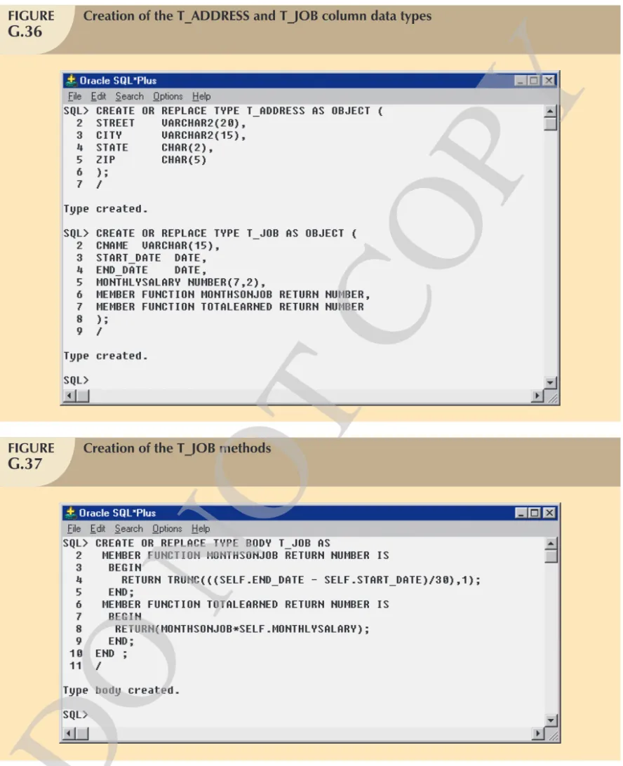
Keep in mind that the OO environment allows you to create abstract data types from base data types. For example, NAME, ADDRESS, and DOB are composite attributes that can be implemented through classes or ADTs. To illustrate that point, Name, Address, and DOB have been defined to be abstract data types in Figure G.17.
As you examine Figure G.17, note that the Person class now contains attributes that point to objects of other classes or abstract data types. The new data types for each instance variable of the class Person are shown in Figure G.18.
Theobject space,orobject schema,is used to represent the composition of the state of an object at a given time.
FIGURE
G.16
State of a Person object instance
System-generated PERSON OID: NAME ADDRESS DOB SEX AGE X20 John D. Smith
123 Main Street, Miami, FL 37457 23-Nov-1974 M 32 Instance variable values
FIGURE
G.17
Defining three abstract data types
NAME ADDRESS STREET_NUM s STREET s APARTMENT s CITY s STATE s ZIP i DOB FIRST_NAME s MIDDLE_NAME s LAST_NAME s DAY i MONTH i YEAR i
s = string data type i = integer data type
FIGURE
G.18
Object representation for instances of the class Person with ADTs
Abstract data types PERSON
NAME ADDRESS DOB SEX
AGE integer Base data types
Instance variables Data Types NAME ADDRESS DOB string
DO NOT
COPY
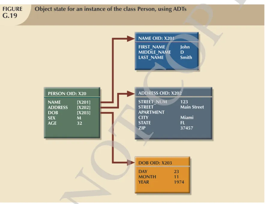
The object’s state for an instance of class Person is illustrated in Figure G.19. As you examine Figure G.19, note the use of OIDs to reference other objects. For example, the attributes NAME, ADDRESS, and DOB now contain an OID of an instance of their respective class or ADT instead of the base value. The use of OIDs for object references avoids the data consistency problem that would appear in a relational system if the end user were to change the primary key value when changing the object’s state. That is because the OID is independent of the object’s state.
To illustrate this point further, a rental property application will be used by which many rental properties and the persons living in them are tracked. In that case, two people living at the same address are likely to reference the same Address object instance. (See Figure G.20.) This condition is sometimes labeled asreferential object sharing. A change in the Address object instance will be reflected in both Person instances.
Figure G.20 illustrates the state of two different object instances of the class Person; both object instances reference the same Address object instance. Note that Figure G.20 depicts four different classes or ADTs: Person (two instances), Name (two instances), Address, and DOB (two instances).
G.4.2 Class-Subclass Relationships
Do you remember that classes inherit the properties of their superclasses in the class hierarchy? That property leads to the use of the label “is a” to describe the relationship between the classes within the hierarchy. That is, an employee is aperson and a studentis aperson. This basic idea is sufficiently important to warrant a more detailed illustration based on the class hierarchy. (See Figure G.21.)
FIGURE
G.19
Object state for an instance of the class Person, using ADTs
PERSON OID: X20 NAME [X201] ADDRESS [X202] DOB [X203] SEX M AGE 32 ADDRESS OID: X202 STREET_NUM 123 STREET Main Street APARTMENT CITY Miami STATE FL ZIP 37457 NAME OID: X201 FIRST_NAME John MIDDLE_NAME D LAST_NAME Smith DOB OID: X203 DAY 23 MONTH 11 YEAR 1974
DO NOT
COPY
In the hierarchy shown in Figure G.21, the Employee object is described by seven attributes, shown in Figure G.22. Social Security number (SS#) is recorded as a string base data type, and SALARY is recorded as an integer base data type. The NAME, ADDRESS, DOB, SEX, and AGE are all inherited from the Person superclass.
FIGURE
G.20
Referential object sharing
PERSON OID: X20 NAME [X201] ADDRESS [X202] DOB [X203] SEX M AGE 32 ADDRESS OID: X202 STREET_NUM 123 STREET Main Street APARTMENT CITY Miami STATE FL ZIP 37457 NAME OID: X201 FIRST_NAME John MIDDLE_NAME D LAST_NAME Smith DOB OID: X203 DAY 23 MONTH 11 YEAR 1974 DOB OID: D45R DAY 20 MONTH 11 YEAR 1976 PERSON OID: X26 NAME [1029] ADDRESS [X202] DOB [D45R] SEX F AGE 30 NAME OID: 1029 FIRST_NAME Mary MIDDLE_NAME S LAST_NAME Smith Superclass Person
Employee Student Subclasses
FIGURE
G.21
Class hierarchy
DO NOT
That example is based on the fact that the OODM supports theclass-subclass relationship, for which it enforces the necessary integrity constraints. Note that the relationship between a superclass and its subclasses is 1:M; that is, if you assume single inheritance, each superclass can have many subclasses and each subclass is related to only one superclass.
G.4.3 Interobject Relationships: Attribute-Class Links
In addition to supporting the class-subclass relationship, the OODM supports the attribute-class relationship. An attribute-class relationship, or interobject relationship, is created when an object’s attribute references another object of the same or different class.
The interobject relationship is different from the class-subclass relationship explored earlier. To illustrate this difference, let’s examine the class hierarchy for the EDLP (Every Day Low Prices) Retail Corporation, shown in Figure G.23.
EMPLOYEE SS# NAME ADDRESS DOB SEX AGE SALARY
Attributes inherited from the Person superclass
FIGURE
G.22
Employee object representation
Root Object
Manufacturer Item Person Facility
Store Warehouse Employee Stocker Cashier Secretary Clerk Manager
FIGURE
G.23
Class hierarchy for the EDLP Retail Corporation
DO NOT
As you examine Figure G.23, note that all classes are based on the Root Object superclass. The class hierarchy contains the classes Manufacturer, Item, Person, and Facility. The Facility class contains the subclasses Warehouse and Store. The Person class contains the subclass Employee, which, in turn, contains the subclasses Manager, Clerk, Secretary, Cashier, and Stocker. The following discussion will use the simple class hierarchy shown in Figure G.23 to illustrate basic 1:M and M:N relationships.
Representing 1:M Relationships
Based on the class hierarchy in Figure G.23, a one-to-many relationship exists between Employee and Facility: each Employee works in only one Facility, but each Facility has several Employees. Figure G.24 shows how that relationship may be represented.
As you examine the relationship between Employee and Facility portrayed in Figure G.24, note that the Facility object is included within the Employee object and vice versa; that is, the Employee object is also included within the Facility object. The following techniques will be used to examine the relationships in greater detail:
쐌 Related classes are enclosed in boxes to make relationships more noticeable.
쐌 The double line on the boxes’ right side indicates that the relationship is mandatory.
쐌 Connectivity is indicated by labeling each box. In this case, a 1 was put next to Facility in the Employee object to indicate that each employee works in only one facility. TheMbeside Employee in the Facility object indicates that each facility has many employees.
Note that the ER notation is used to represent a mandatory entity and to indicate the connectivity of a relationship (1:M). The purpose of the notation is to maintain consistency with earlier diagrams.
FIGURE
G.24
Representing a 1:M relationship
EMPLOYEE SS# NAME ADDRESS DOB SEX AGE SALARY FACILITY 1 FACILITY CODE NAME ADDRESS BUDGET EMPLOYEE M = mandatory participation 1,M = connectivityDO NOT
COPY
Rather than just include the object box within the class, the preference is to use a name that is descriptive of the class characteristicbeing modeled. That procedure is especially useful when two classes are involved in more than one relationship. In those cases, the attribute’s name should be written above the class box and the class box should be indented to indicate that the attribute will reference the class. For example, two relationships between Employee and Facility can be represented by using WORKS_AT and WORKERS, as indicated in Figure G.25. Note that two relationships exist:
1. The 1:M relationship is based on the business rule “each facility employs many employees, and each employee is employed by only one facility.”
2. The 1:1 relationship is based on the business rule “each facility is managed by only one employee, and each manager manages only one facility.”
As you examine Figure G.25, note that the relationships are represented in both participating classes. That condition allows you to invert the relationship, if necessary. For example, the Facility object within the Employee object represents the “Manager_of” relationship. In this case, the Facility object is optional and has a maximum connectivity of 1. The Employee and Facility objects are examples of compound objects. Another type of 1:M relationship can be illustrated by examining the relationship between employees and their dependents. To establish that relationship, you first create a Dependent subclass, using Person as its superclass.Note that a Dependent subclass cannot be created by using Employee as its superclass because the class hierarchy represents an “is a” relationship. In other words, each Manager is an Employee, each Employee is a Person, each Dependent is a Person, and each Person is an Object in the object space—but each Dependent is not an Employee. Figure G.26 shows the proper presentation of the relationship between Employee and Dependent.
As you examine Figure G.26, note that Dependent is optional to Employee and that Dependent has a 1:M relationship with Employee. However, Employee is mandatory to Dependent.The weak entity concept disappears in the OODM because each object instance is identified by a unique OID.
FIGURE
G.25
Representing 1:1 and 1:M relationships
EMPLOYEE SS# NAME ADDRESS DOB SEX AGE SALARY WORKS_AT: FACILITY 1 FACILITY CODE NAME ADDRESS BUDGET WORKERS: EMPLOYEE M
Note: the Manager attribute indicates the facility’s general manager FACILITY 1 MANAGER_OF: EMPLOYEE 1 MANAGER:
DO NOT
COPY
Representing M:N Relationships
Using the same EDLP Retail Corporation class hierarchy, a many-to-many (M:N) relationship can be illustrated by exploring the relationship between Manufacturer and Item, as represented in Figure G.27. Figure G.27 depicts a condition in which each Item may be produced by many Manufacturers and each Manufacturer may produce many Items. Thus, Figure G.27 represents a conceptual view of the M:N relationship between Item and Manufacturer. In this representation, Item and Manufacturer are both compound objects.
Also note that the CONTACT attribute in the Manufacturer class in Figure G.27 references only one instance of the Person class. A slight complication arises at this point. It is likely that each contact (person) has a phone number, yet no phone number attribute was included in the Person class. In that case, the designer may add the attribute so it will be available to all Person subclasses.
FIGURE
G.26
Employee-dependent relationship
EMPLOYEE SS# NAME ADDRESS DOB SEX AGE SALARY WORKS_AT: FACILITY 1 DEPENDENT NAME ADDRESS DOB SEX AGE DEPENDENT_OF: EMPLOYEE 1 DEPENDENT M DEPENDENTS:FIGURE
G.27
Representing the M:N relationship
MANUFACTURER CODE NAME ADDRESS CONTACT: PERSON 1 ITEM CODE DESCRIPTION QUANTITY UNIT_PRICE MANUFACTURERS: MANUFACTURER M ITEM M ITEMS:
DO NOT
COPY
Representing M:N Relationships with an Intersection Class
Suppose you add a condition to the just-explored ITEM class that allows you to track additional data for each item. For example, let’s represent the relationship between Item and Facility so that each Facility may contain several Items and each Item may be located at several Facilities. In addition, you want to track the quantity and location (aisle and row) of an Item at each Facility. Those conditions are illustrated in Figure G.28. The right square bracket “]” in Figure G.28 indicates that the included attributes are treated as one logical unit. Therefore, each Item instance may contain several occurrences of Facility, each accompanied by related values for the AISLE, ROW, QTY_ON_HAND and UNIT_PRICE attributes. The inverse is true for each instance of Facility. The Item and Facility objects in this relationship are hybrid objects with a repeating group of attributes. Note that the semantic requirements for this relationship indicate that the Item or Facility objects are accessed first so the aisle, row, and quantity on hand are known for each item.
To translate the preceding discussion to a more relational view of the M:N scenario, you would have to define an
intersection (bridge)class to connect both Facility and Item and store the associated attributes. In that case, you might create a Stocked_Item associative object class to contain the Facility and Item object instances and the values for each of the AISLE, ROW, QTY_ON_HAND and UNIT_PRICE attributes. Such a class is equivalent to the Interclass_Connection construct of the Semantic Data Model. Figure G.29 shows how the Item, Facility, and Stocked_Item object instances might be represented.
Having examined the depiction of the basic OO relationships, you can represent the object space as shown in Figure G.30.
FIGURE
G.28
Representing the M:N relationship with associated attributes
ITEM CODE DESCRIPTION MANUFACTURERS: FACILITY CODE NAME ADDRESS BUDGET WORKERS: MANUFACTURER M FACILITY M EMPLOYEE M MANAGER: EMPLOYEE 1 AISLE ROW QTY_ON_HAND UNIT_PRICE ITEM M AISLE ROW QTY_ON_HAND UNIT_PRICE
DO NOT
COPY
FIGURE
G.29
Representing the M:N relationship with intersection class
ITEM CODE DESCRIPTION MANUFACTURERS: STOCKED_ITEM ITEMS_STOCKED: MANUFACTURER M STOCKED_ITEM M STOCKED_AT: ITEM 1 LOCATED_AT: FACILITY 1 UNIT_PRICE FACILITY CODE NAME ADDRESS BUDGET WORKERS: EMPLOYEE M MANAGER: EMPLOYEE 1 STOCKED_ITEM M AISLE ROW QTY_ON_HAND ITEMS_STORED:
FIGURE
G.30
Object space representation
OID: A001 11237 COLOR TV 13" [V3402] [Z45621] 29.95
Collection of Manufacturer class OID: Z3402 [X333], ..., ..., OID: X333 ACME CORP. ... ...
Collection of Stocked_Item class OID: Z45621 [ST0975], ..., ..., OID: Z67461 [ST0975], ..., ..., OID: ST0975 OID: C0980 W010 MAIN WAREHOUSE [V3245] $100,000.00 [S2390] [M5764] [Z67461] Manufacturer Facility Stocked_Item Two instances of the same class Item [A001] [C0980] 123 03 450.00
DO NOT
COPY
Because Figure G.30 contains much critical design information, you should examine the following points in particular:
쐌 The Stocked_Item associative object instance contains references to an instance of each related (Item and Facility) class. The Stocked_Item intersection class is necessary only when you must keep track of the additional information referred to earlier.
쐌 The Item object instance in this object schema contains the collection of Stocked_Item object instances, each one of which contains a Facility object instance. The inverse of that relationship is also true: a Facility object instance contains the collection of Stocked_Item object instances, each one of which contains an Item object instance.You should realize that those two relationships represent two different application views of the same object schema. It is desirable for a data model to provide such flexibility.
쐌 The interobject references use the OID of the referenced objects in order toaccessandincludethem in the object space.
쐌 The values inside square brackets “[ ]” represent the OID of an object instance of some class.The “collection of” classes represent a class of objects in which each object instance contains a collection of objects of some class. For example, the Z3402 and Z45621 OIDs reference objects that constitute a collection of Manufacturers and a collection of Stocked_Items, respectively.
쐌 In the relational model, the ITEM table would not contain any data regarding the MANUFACTURERs or the STOCKED_ITEMs in its structure. To provide (combined) information about ITEM, STOCKED_ITEM, and FACILITY, you would have to perform a relational join operation. The OODM does not need joins to combine data from different objects because the Item object contains the references to the related objects; those references are automatically brought into the object space when the Item object is accessed.
G.4.4 Late and Early Binding: Use and Importance
A desirable OODM characteristic is its ability to let any object’s attribute contain objects that define different data types (or classes) at different times. With that feature, an object can contain anumeric valuefor a given instance variable and the next object (of the same class) can contain acharacter valuefor the same instance variable. That characteristic is achieved through late binding. Withlate binding, the data type of an attribute is not known until execution time or run time. Therefore, two different object instances of the same class can contain values of different data types for the same attribute.
In contrast to the OODM’s ability to use late binding, a conventional DBMS requires that a base data type be defined for each attribute at the time of its creation. For example, suppose you want to define an INVENTORY to contain the following attributes: ITEM_TYPE, DESCRIPTION, VENDOR, WEIGHT, and PRICE. In a conventional DBMS, you create a table named INVENTORY and assign a base data type to each attribute, as shown in Figure G.31. Recall from earlier chapters that when the designer is working with conventional database systems, (s)he must define the data type for each attributewhen the table structure is defined. That approach to data type definition is called early binding. Early binding allows the database to check the data type for each of the attribute’s values at compilation or definition time. For instance, the ITEM_TYPE attribute in Figure G.31 is limited to numeric values. Similarly, the VENDOR attribute may contain only numeric values to match the primary key of some row in a VENDOR table with the same numeric value restriction.
Now let’s take a look at Figure G.32 to see how an OODM would handle this early-binding problem. As was true in the conventional database environment, the OODM allows the data types to be defined at creation time. However, quiteunlikethe conventional database, the OODM allows the data types to be user-defined ADTs. In this example of early binding, the abstract data types Inv_type, String_of_characters, Vendor, Weight, and Money are associated with the instance variables at definition time. Therefore, the designer may define the required operations for each data type. For example, the Weight data type can have methods to show the weight of the item in pounds or kilograms. Similarly, the Money data type may have methods to return the price as numbers or letters denominated in U.S. dollars, euros, or British pounds. (Remember that abstract data types are implemented through classes.)
DO NOT
In a late-binding environment, the object’s attribute data type is not known prior to its use. Therefore, an attribute can have any type of value assigned to it. Using the same basic data set described earlier, Figure G.33 shows the attributes (instance variables) ITEM_TYPE, DESCRIPTION, VENDOR, WEIGHT, and PRICE without a prior data type definition. Because no data types are predefined for the class instance variables, two different objects of the Inventory class may have different value types for the same attribute. For example, ITEM_TYPE can be assigned a character value in one object instance and a numeric value in the next instance. Late binding also plays an important role in polymorphism, allowing the object to decide which implementation method to use at run time.
G.4.5 Support for Versioning
Versioningis an OODM feature that allows you to track the history of change in the state of an object. Versioning is a very powerful modeling feature, especially in computer-aided design (CAD) environments. For example, an engineer using CAD can load a machine component design in his/her workstation, make some changes, and see how those changes affect the component’s operation. If the changes do not yield the expected results, the engineer can
FIGURE
G.31
Inventory table with predetermined (base) data types
Table: INVENTORY
Attributes Conventional (Base) Data Type ITEM_TYPE Numeric DESCRIPTION Character VENDOR Numeric WEIGHT Numeric PRICE Numeric
FIGURE
G.32
Inventory class with early binding
Class: INVENTORY
Instance variables Type ITEM_TYPE Inv_type DESCRIPTION String_of_characters VENDOR Vendor WEIGHT Weight PRICE Money
DO NOT
COPY
undo those changes and restore the component to its original state. Versioning is one of the reasons the OODBMS is such a strong player in the CAD and computer-aided manufacturing (CAM) arenas.
G.5 OODM AND PREVIOUS DATA MODELS: SIMILARITIES AND DIFFERENCES
Although the OODM has much in common with relational and ER data models, the OODM introduces some fundamental differences. The following summary is designed to offer detailed comparisons to help clarify the OODM characteristics introduced in this chapter.
G.5.1 Object, Entity, and Tuple
The OODM concept ofobjectextends well beyond the concept ofentityortuplein other data models. Although an OODM object resembles the entity and the tuple in the ER and relational models, an OODM object has additional characteristics, such as behavior, inheritance, and encapsulation. Those OODM characteristics make OO modeling more natural than ER and relational modeling. In fact, the ER and relational models often force the designer to create new artificial entities to represent real-world entities. For example, in the ER model, an invoice is usually represented by two separate entities; the second (LINE) entity is usually weak because its existence depends on the first (INVOICE) entity and its primary key is partially derived from the INVOICE entity. (See Figure G.34.)
As you examine Figure G.34, note that the ER approach requires the use of two different entities to model a single real-world INVOICE entity. That artificial construct is imposed by the relational model’s inherent limitations. The ER model’s artificial representation introduces additional overhead in the underlying system. In contrast, the OODM’s INVOICE object is directly modeled as an object into the object space, or object schema.
G.5.2 Class, Entity Set, and Table
The concept of class can be associated with the ER and relational models’ concepts of entity set and table, respectively. However, class is a more powerful concept that allows not only the description of the data structure, but also the description of the behavior of the class objects. A class also allows for both the concept and the implementation of abstract data types in the OODM. The ADT is a very powerful modeling tool because it allows the end user to create new data types and use them like any other base data type that accompanies a database. Thus, the ADT yields an increase in thesemanticcontent of the objects being modeled.
FIGURE
G.33
OODM Inventory class with late binding
Class: INVENTORY
Instance variables Type ITEM_TYPE
DESCRIPTION
VENDOR No data type is known when the class is created WEIGHT
PRICE
DO NOT
G.5.3 Encapsulation and Inheritance
ADT brings two other OO features that are not supported in previous models: encapsulation and inheritance. Classes are organized in class hierarchies. An object belonging to a class inherits all properties of its superclasses. Encapsulation means that the data representation and the method’s implementation are hidden from other objects and from the end user. In an OODM, only the methods can access the instance variables. In contrast, the conventional system’s data components or fields are directly accessible from the external environment.
Conventional models do not incorporate the methods found in the OODM. The closest thing to methods is the use of triggers and stored procedures in SQL databases. However, because triggers do not include the encapsulation and inheritance benefits that are typical of the object model’s methods, triggers do not yield the same functionality as methods.
G.5.4 Object ID
The object ID (OID) is not supported in either the ER or the relational model. Although database users may argue that Oracle Sequences and MS Access AutoNumber provide the same functionality as an OID, that argument is trueonly to the extent that they can be used to uniquely identify data elements. However, unlike the object model, in which the relationships are implicit, the relational model still uses value-based relationships such as:
SELECT *
FROM INVOICE, INV_LINE
WHERE INVOICE.INV_ID = INV_LINE.INV_ID;
The hierarchical and CODASYL models support some form of ID that can be considered similar to the OID, thus supporting the argument presented by some researchers who insist that the OO evolution is a step back on the road to the old pointer systems. Therefore, OO-based systems return to the modeling and implementation complexities that were typical of the hierarchical and network models.
G.5.5 Relationships
The main property of any data model is found in its representation of relationships among the data components. The relationships in an OODM can be of two types: interclass references or class hierarchy inheritance. The ER and the relational models use avalue-basedrelationship approach. Using a value-based approach means that a relationship
INVOICE DATE
NUMBER
CUSTOMER 1
LINE M
OO Data Model ER Data Model