Italian Journal of Science & Engineering
Vol. 1, No. 1, June, 2017
Simulation and Development of Instrumental Setup to Be Used
for Cement Grouting of Sand Soil
Yaser Gamil
a*, Ismail Bakar
a, Kemas Ahmed
aa Faculty of Civil and Environmental Engineering, University Tun Hussein Onn Malaysia, Johor, Malaysia.
Abstract
Most of Arab countries areas are occupied with deserts that is covered with sandy soil. Thus, it is necessary to make use of this huge volume of sand to be as construction materials. It is proven that, sand is initially uneven and unstable. It requires pre-modifications of its primer properties in order to be used as construction materials. One of the common techniques is injecting the sand with binders. Many grouting techniques has been implanted to modify or rehabilitate the structure of soil but for sandy soil the methods has not yet been introduced Therefore, this study aimed at developing simulation and instrumental setup to be used for cement grouting. The simulation has been custom made and utilized to form grouted samples for further investigation. The method of injecting sand is by applying pressure to produce force flow in order to be injected into the sand. After the formation of injected sand samples, an experimental investigation was carried out to determine the basic properties. Shear strength of the sand was recorded before and after grouting. It was found that, the shear strength has increased after injecting the sand with cement and the setup has produced accurate grouted samples with even distribution of the cement mix. The results of the various investigations conclusively proved that grouting can be used as an effective way to improve the strength characteristics significantly and can also contribute to the stabilization of sand.
Keywords:
Cement Grouting; Sand;
Soil Stabilization; Instrumental Setup.
Article History:
Received: 15 February 2017
Accepted: 05 April 2017
1-
Introduction
Grouting is widely-used technique for strengthening soil and rehabilitating cracks in concrete structures [1]. It is a cost-effective method and environmental friendly because it requires minimum binders [2, 3]. Moreover, it requires accurate tools and machinery to carry out an effective grouting that possibly improve the property of grouted soil [2].
Cement is one of the most common materials used to perform grouting either for soil or for concrete cracks rehabilitation [3]. It has been used to inject several types of soil that has the characteristics of conformation of different particles size distribution [4]. This technology is defined as the injection of specially formulated cement-based mixes into the ground to improve its strength or reduce permeability [3-5]. Cement grouting is performed by drilling holes into the foundation to intercept open cracks, joints, fissures or cavities, then pumping under pressure balanced and stabilized grout mixes using a combination of cement, water, and additives. Work generally begins with a base mix and is modified during the grouting process with subsequent mixes in order to achieve closure by reducing permeability to a predetermined value [6]. This study introduced a new simulation for grouting sandy soil and the grouted sand samples investigated experimentally in the laboratory to determine the effect of cement grouting to the sand properties such as shear strength and unconfined compressive strength.
This study aims to develop grouting setup that is used in the laboratory to form grouted sand samples which finally used to compare the results of the effects of injecting cement into sand. The second objective is to carry out laboratory investigation of the unconfined compressive strength
For this study, there are several significances that would be obtained at the end of this study, firstly a grouting testing machine to form grouted samples is fabricated and can be used for further studies and researches in grouting study either for sand or other materials for the purpose of improving properties for the chosen study materials. This
*CONTACT: [email protected]
machine can form grouted samples with specified dimensions.in additions to that, this study mainly achieved and studied the sand stabilization by cement grouting.
2-
Literature Review
Grouting has been intensively studied by many researchers. It has been advance implemented in many applications of the built environment for the purpose of crack rehabilitation or modification of soil properties. In addition to that, it is used for slope stabilization in steep phenomenon and has been considered as an effective method to produce stable slope that help to reduce environmental disasters [4, 5, 7].
Over the years, the method of performing grouting is changing with the advancement of technology and that has significantly resulted in saving cost and time for the process. Hence, grouting has long played a significant remedial role in ground improvement, soil stabilization and concrete rehabilitations [7-9].
A study by Nikbakhtan et al [3] has used jet grouting to rehabilitate the structure and avoid slope failure of Shahriar dams in Iran. It was found that, the grouting has improved the state of the dam. Jet grouting can be also used in other different applications. Therefore, it should be handled with expertise and skilled labors to avoid negative effect on the structure [8].
Underground structures are the most difficult structure for rehabilitation and monitoring [9, 10] especially where constructed on soft ground often requires the soil to be improved in order to ensure the safety and the stability of surrounding buildings. Grout permeation is an efficient technique for reducing permeability and for increasing stiffness and strength of coarse-to-medium grained soils with low initial mechanical properties [1, 9, 10].
Many techniques have been introduced in grouting technology. Mixing in place is one of the most common technique and has shown to be very effective method for construction of soil-cement piles in place. Additive stabilization of foundation soils for structures is used mainly in connection with grouting and electro-osmosis, with additional application to the treatment of expansive soils to shallow depths [11]. Besides, the method of injecting the soil by the mean of applying pressure into certain soil structure and that might be sometimes ineffective due to the non-uniformity of soil particles beneath the surface [3, 12].
There are 5 types of grouting technique that has been introduced in construction. Firstly, Permeation Grouting which is the core principle of permeation is to fill the voids naturally present in the soil with grout, without changing the original soil structure and volumetric. This is probably the oldest grouting technique, the first documented applications dating back to the early 1800’s, and also the most experimented and researched [2, 12]. Secondly, Jet Grouting which is defined as the youngest grouting techniques, jet grouting overcomes the limitations related to the soil grain size distribution, typical of the traditional grouting techniques. The soil structure is virtually obliterated by high pressure - high velocity jets. Ultimately, the remaining soil is mixed in situ with cement based grouts [13]. Another advanced technique called Hydro fracturing: this typically French grouting application aims at injecting grout in the ground at relatively high pressure, thus fracturing the ground itself and creating lenses of grout, mainly along horizontal planes [2]. The third technique is compaction grouting which is used for high cohesion and rigidity grouts, often containing diverse granulometries of aggregates, are injected to form bulbs around the injection pipe, inducing densification in the surrounding soil. Compaction grouting is not typically used for excavation support; however, compensation grouting, a variant of this grouting concept, is increasingly used for control of tunneling induced settlement. Remarkable accomplishments have been recently achieved in major tunneling projects in Europe, Canada, and USA [2]. Figure 1 presents the most common techniques of grouting which have been implemented in many construction applications.
Figure 1. Types of grouting techniques for grouting engineering [2].
themselves quickly [14, 15]. Flowability of the fresh mixed cement grout (CG) has to be considered in order to provide smooth path for the grout to flow. From previous studies, [16, 17]. Grouting material is very substantial element to produce efficient grouting. Grout consists of two materials cement and water which are mixed together to specified ratio in order to ease the flow of grout into the sand. Fluids with high internal friction are not optimal for injection, as high pressures are required to pump them over significant distances [14]. Ordinary Portland Cement (OPC) is the most common material that has been used in construction and soil stabilization. In term of water quality, it is suggested that, water suitable for drinking may be regarded as suitable for use in grout. Ordinarily the presence of harmful impurities (e. g., alkalis, organic and mineral acids, deleterious salts, or large quantities of silt) is known in local water sources [18]. Hence, this study provided a complete set of instrument and experimental results.
3-
Research Methodology
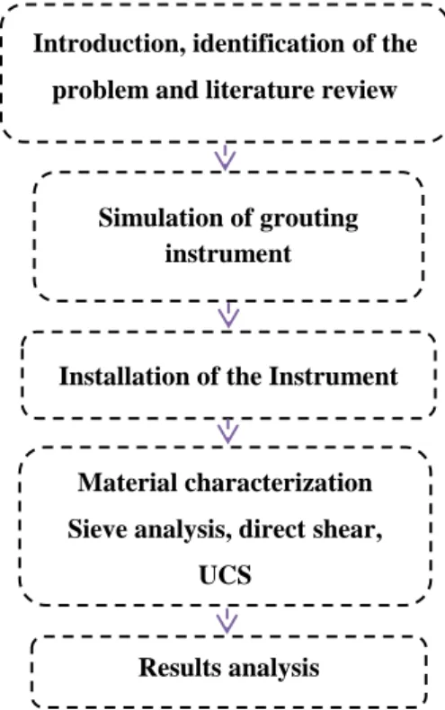
Figure 2 illustrates the sequential methods adopted to carry out this research. Firstly, the study introduces the current practices and norms in grouting technology then defining the issue and lack of instruments that is specific to suit the nature of sand soil. Then, simulating the equipment using certain aided software to be sent for design and fabrication in the factory. The equipment then undergone certain calibrations and experiments to rectify its functionality and efficiency. Then, the materials were prepared and designed to produce the hybrid of grouting. The natural sand was placed into the specific molds then injected with the mix under certain and controlled pressure vacuum.
Figure 2. Methodology flow chart.
4-
Parameters of the Study
In this study, several important parameters were investigated which includes, water cement ratio is an important parameter consider in the preparation of the grout mix since it contributes to the accessibility of the grout to pass into the sand, Density of sand can vary depending on the grain size and moisture content and how tightly it is compacted when sand is wet, the tests should be performed with medium sand corresponding to a dry unit weight of approximately16 kN/m3,Shear strength of soils is an important aspect in many foundation engineering problems such
as the bearing capacity of shallow foundations and piles, the stability of the slopes of dams and embankments, and lateral earth pressure on retaining walls [1], and Unconfined compressive strength Hence , To observe properties of the grout in soil, a set-up should be made to hold molds where grout is injected into sand. A drill press is used to drill holes for filter pieces to prevent sand from leaving the mold set-up and draining through the tubes. Once the grout is injected into the soil, the grouted soil is then removed from the set-up and further tested via unconsolidated compression test.
Introduction, identification of the
problem and literature review
Simulation of grouting instrument
Results analysis Installation of the Instrument
Material characterization
Sieve analysis, direct shear,
5-
Grouting Instrument Setup
Instruments have to be set according to the modeling and simulation proposed in this study. Proper setup of the instruments can ease the procedures of experiments and collecting data.
Figure 3. Grouting apparatus early proposed simulation.
Figure 3 shows the instrument setup which is used to run the grouting technique:
1. Pressure gauge used to regulate the pressure in accordance to the easiness of the grout flow into the sand samples.
2. Valve to control the grout flow.
3. Grout container is used to maintain and keep the grout from any external effects
4. Pressure chamber used to supply pressure into the grout in order to push it toward the opening.
5. Mold which contains the sand sample which can be opened in order to easily take out the grouted samples.
6. Excess grout used to keep the excess grout from being ousted to mess up the apparatus.
7. Side Mold holder to easily and firmly hold the mold from moving or tending.
8. Top and bottom mold holder used to hold and easily open the mold to take out the samples.
9. Pipe system is used as grout flow route to the samples.
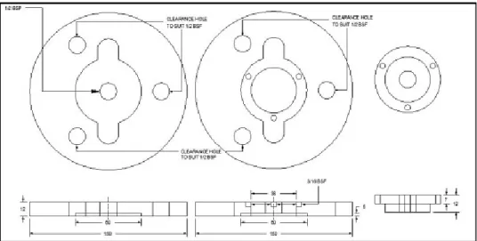
Figure 5. Side view of the mould.
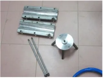
Figure 6.The grouting equipment.
Figure 6 shows the equipment which has been designed for the purpose of conducting this technique the equipment is ordered from the supplier.
Figure 7. Mould for sand sample.
opening used for the flow of excess grout. The figure below also shows the mould when they are installed and they can be easily moved and opened.
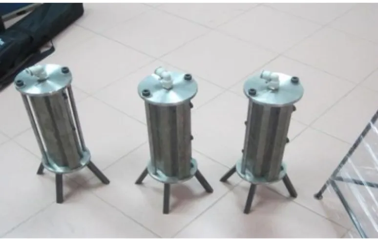
Figure 8. Grouting mold.
6-
Results and Analysis
There are several labs testing which have to be conducted to identify and study the grouting technique as well as to determine the characteristics and behaviors of sand under grouting test. The total mass is 115 g.
6-1- Sieve Analysis of Sand
Sieve analysis is performed in this study in order to provide specific grain size distribution so that can contribute to the easiness of discussing the engineered properties of sand and for classification purpose. Sieving can be performed in either wet or dry conditions. However, in this study only dry sieve analysis was carried out. The total mass used was 115.5g the sieve analysis is calculated in the Table 1.
Table 1. Sieve analysis of Sand.
Sieve (mm) Mass (gr) % retained % passing 10.0 0 0.0 100.0
6.3 5.5 4.8 95.2
2.0 25.7 22.3 73.0
1.00 23.1 20.0 53.0
0.60 22 19.0 33.9
0.30 17.3 15.0 19.0
0.150 12.7 11.0 8.0
0.063 6.9 6.0 2.0
pan 2.3 2.0
Table 1 shows the results of sieve analysis for sand soil. It is illustrated that the grades sizes range in less than 10mm and for the effective sieve size of 0.063 the percentage passing is less than 10%.
From Figure 9 the value of D10 = 0. 17mm.Uniformity coefficient (Cu): This parameter is defined as where D60 is
diameter corresponding to 60% finer.
From the graph D60 = 1.5 mm, D10= 0.17 mm.
𝐶
𝑢=
𝐷60
𝐷10
= (
1.5
0.17
) = 8.82
(1)
Coefficient of gradation (Cc) [19]: This parameter is defined as
𝐶𝑐 = 𝐷30 2
𝐷60 ∗ 𝐷10
(2)
From Figure 9 the correspondent value of D30=0.51 hence, the value of Cc=1.01.
The results calculated form the graph and formula shown that: The effective 𝐷10= 0.17 𝑚𝑚, the value of 𝐷60=
1.5 𝑚𝑚, Coefficient of uniformity 𝐶𝑢= 8.82, effective 𝐷30=0.51 and the coefficient of gradation 𝐶𝑐=1.01 the soil is classified based on the several standards.
1. Unified soil classification system (USCS) it is shown that the 𝐶𝑢=8.82 > 4 and the 𝐶𝑐=1.01 is between 1 and 3 so
that the type of soil is a well-graded clean sand (SW).
2. Based on American Association of State Highway and Transportation Officials (AASHTO) it is found that this soil is under the SubgroupA-1-b includes those materials consisting predominantly of coarse and with or without a well-graded soil binder.
6-2- Direct Shear Test of Non-Grouted Sand
Direct shear test was conducted before grouting to provide reference for later comparison with after grouting samples.
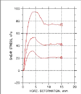
Figure 10. Direct shear test results
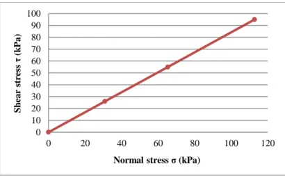
Figure 10 show the horizontal deformation vs. shear stress it is shown that the shear stress increases gradually for the first test the highest value of shear is approximately 22 kPa and the horizontal displacement is 15 mm .and for the second test the highest shear stress is about 54 kPa and the horizontal displacement is the same as test 1 and for the 3rd test the highest shear stress is approximately 93 kPa and the displacement is about 15mm. Using the data in Figure 11 and using the Equation (3) to determine the normal stress [19]:
Figure 11. Shear stress vs. normal stress.
6-3- Installation of the Instrument
The instrument was installed in the Research Center for Soft Soil (RECESS-UTHM) nearby a pressure supplier so that would be easier for using the pressure for grouting.
Figure 12. The installation of grouting apparatus.
6-4- Formation of Grouted Sand Sample
Figure 13 shows the process of cutting the grouted samples to the size of 𝐷 = 45 𝑚𝑚 and 𝐻 = 90 𝑚𝑚.
Figure 13. Grouted sand samples.
6-5- Unconfined Compression Test for the Samples
The tests were conducted for the samples using unconfined compression test apparatus in order to study and investigate the development of compressive strength for the grouted samples.
0 10 20 30 40 50 60 70 80 90 100
0 20 40 60 80 100 120
S
h
ea
r
str
ess
τ
(k
Pa
)
0 0.1 0.2 0.3 0.4 0.5 0.6
0 0.05 0.1 0.15 0.2
str
ess
M
Pa
strain ɛ
Figure 14. Grouted sand failure.
The samples were placed at room temperature and set for different curing time.
For the first day, the unconfined compression test was conducted using soil apparatus since the maximum load for the equipment is only 5 KN so that it was only suitable for one day curing time the unconfined compression test was conducted to determine the stress and strain for one day curing time as shown below
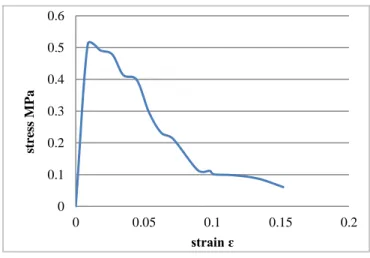
Figure 15. Stress vs. strain for one day curing.
Figure 15 shows the stress vs. strain which explains the behaviour of the grouted sand under the application of axial load till failure. The stress increased up to maximum then decreases gradually when the strain increases because the crack failure also increased while conducting the test. The stress is not quite uniform throughout the specimen, and there will always be some location.
The unconfined compression test UCT was conducted for 3 days curing time and the maximum strength for 0.85 and 0.75 water cement ratio. For w/c ratio 0.85 the compressive strength is 0.71 MP. And for 0.75 w/c ratio is 0.68 MP.
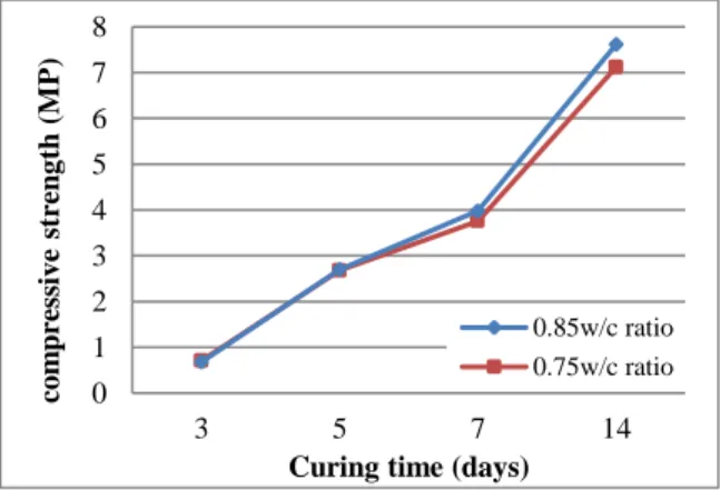
Figure 16. Development of strength vs. w/c ratio in different curing time.
Figure 16 demonstrates the development of strength in different curing days with respective to fixed water to cement ratio. For 3 days curing time it can be analysed that when the water cement ratio is high the strength is higher but there were difficulties to run the grouting under 0.85 water cement ratio because the viscosity is high and the flow required higher pressure to inject the grout into the sand.
The samples also were tested in 7 days curing time the results is almost the same with 5 days but the strength is developing. Figure 16 shows the result of compressive strength in seven days curing time and the analysis is similar with 5 days curing time with 0.85 water cement ratio the strength developed to 3.76 MP. It also shows the result of compressive strength in seven days curing time and the analysis is similar with 5 days curing time with 0.75 water cement ratio the strength developed to 3.98 MP.
Figure 16 also shows the result of compressive strength in 14 days curing time with 0.85 water cement ratio the strength developed to 7.121 MP.it also shows the compressive strength vs. water cement ratio and the results is similar to 7 days but the strength increased by almost double of that values. The value of the strength with 0.75 w/c ratio is 7.615 MP.
To determine the relationship between strength and curing time for 0.85 and 0.75 w/c ratio. Figure 17 shows the development of strength of grouted sand in different curing time .it is illustrated that the strength developed much higher in 7 days to 14 days curing time.
Figure 17. The compressive strength vs. curing time with respect to w/c ratio
7-
Conclusion
This study has introduced new instrumental setup to be used for grouting samples. The setup exhibit efficient functionality and performed with homogenous distribution of the grouting mix into the sand. It is shown that, the primary characteristics of sand has developed in comparison between before grouting and after grouting such that shear strength and compressive strength. Several concluding remarks are learnt from this study includes the following items:
Grouting technique
This technique is very important to be explored for the purpose of stabilizing sand without excavating the site it is only matter of injecting cement with some chemicals to provide very strong layers with less cost and damages to the surrounding areas. This technique has contributed to the solutions of many geotechnical problems encountered with soft soil and peat as well.
Equipment setup
The equipment used for grouting technique has to be calibrated and monitored in order to provide smooth running and prevent any shortcomings while injecting the grout. Controlling the pressure is a major concern in grouting technique.
Grout materials
Grout materials have to be selected appropriately to minimize the cost needed to precede this technique and provide better results outcome.
Grain size distribution
The grain size has to be tested to know the gradation of the sand which has to be grouted in Figure 9 shows the gradation of sand samples in this study the size was taken from (1-1.18) mm so that it is medium course.
Pre-grouting test
0 1 2 3 4 5 6 7 8
3 5 7 14
co m p re ss iv e str en g th (M P)
Curing time (days)
The were some tests conducted in this study the sieve analysis and direct shear test in order to know the difference between the strength before and after grouting in Figure 10 the shear stress results are shown and discussed
Installation of grouting equipment
The installation of the equipment was in RECESS lab and it was located beside a pressure supplier so that it was easy to use and run the test.
Grouted samples
The first objective of this study is achieved and the grouted samples have been formed for further study.
Testing the grouted samples
The samples were tested using unconfined compression test for different curing time it is shown in Figure15 the stress vs. strain graph this figure provides a better comprehension of the behaviour of grouted sample for one day. In Figure 16 shows the development of strength with respect to curing time and different water cement ratio
Water cement ratio play an important role in the improvement of the strength because the material was used is composite cement.
8-
Recommendations
There are still some developments have to be studied to improve the technique of grouting. And the grouting materials have to be discovered and alternate with other materials like fly ash and biomass which are cheap and can help to reduce the environmental pollutions. There are many researches done on stabilization of sand and there are some misconceptions and discoveries have been extended because there is still not much research done on it in sand soil.
9-
Acknowledgement
Author acknowledges the financial support and scholarship provided by the ministry of higher education in Yemen. It also goes to RECESS, UTHM for facilitating the research process and supplying research materials.
10-
References
[1] Jian-gu, Q. I. A. N., J. I. A. Peng, and Ming-jin CHENG. "Experimental study of grouting pile-soil interface and numerical simulation of bearing behavior of side-grouting uplift pile." Rock and Soil Mechanics 32, no. 4 (2011): 662-668.
[2] Zou, Jin-feng, Liang Li, Xiao-Li Yang, and Zhen-Nan Hu. "Mechanism analysis of fracture grouting in soil." Yantu Lixue(Rock and Soil Mechanics) 27, no. 4 (2006): 625-628.
[3] Nikbakhtan, B., K. Ahangari, and N. Rahmani. "Estimation of jet grouting parameters in Shahriar dam, Iran." Mining Science and Technology (China) 20, no. 3 (2010): 472-477.
[4] Das, Braja M. Soil mechanics laboratory manual. New York, USA: Oxford University Press, 2002. (Pages: 152-165).
[5] Nikbakhtan, B., Y. Pourrahimian, and H. Aghababaei. "The effects of jet grouting on slope stability at Shahriar dam, Iran." In 1st Canada-US Rock Mechanics Symposium. American Rock Mechanics Association, 2007.
[6] CIRIA.”Grouting for engineering “.CRIRIA press London pages, p: 17-22: (2000).
[7] TANG, Hui-ming, Ying-zi XU, and Xin-sheng CHENG. "Research on design theory of lattice frame anchor structure in landslide control engineering [J]." Rock and Soil Mechanics 11 (2004): 000.
[8] Nikbakhtan, Babak, and Morteza Osanloo. "Effect of grout pressure and grout flow on soil physical and mechanical properties in jet grouting operations." International Journal of Rock Mechanics and Mining Sciences 46, no. 3 (2009): 498-505.
[9] Liu, Huabei, and Erxiang Song. "Working mechanism of cutoff walls in reducing uplift of large underground structures induced by soil liquefaction." Computers and Geotechnics 33, no. 4 (2006): 209-221.
[10] Henn, Raymond W. Practical guide to grouting of underground structures. Thomas Telford, 1996.
[11] Mitchell, James K. "In-place treatment of foundation soils." Journal of the Soil Mechanics and Foundations Division 96, no. 1 (1970): 73-110.
[14] Karol, Reuben H. Chemical grouting and soil stabilization, revised and expanded. Vol. 12. Crc Press, 2003.
[15] Au, S. K. A., K. Soga, M. R. Jafari, M. D. Bolton, and K. Komiya. "Factors affecting long-term efficiency of compensation grouting in clays." Journal of Geotechnical and Geoenvironmental Engineering 129, no. 3 (2003): 254-262.
[16] Lim, David May. "01, 2009 (Grouting for Ground Improvement & Water Control)." Journal paper, pages (3-9).
[17] Wiklund, Johan, Mashuqur Rahman, and Ulf Håkansson. "In-line rheometry of micro cement based grouts-a promising new industrial application of the ultrasound based uvp plus pd method." Applied Rheology 22, no. 4 (2012): 42783.
[18] Gustafson, Gunnar, and Håkan Stille. "Stop criteria for cement grouting." Felsbau: Zeitschrift für Geomechanik und Ingenieurgeologie im Bauwesen und Bergbau 25, no. 3 (2005): 62-68.
![Figure 1. Types of grouting techniques for grouting engineering [2].](https://thumb-us.123doks.com/thumbv2/123dok_us/7936560.2109855/2.892.235.683.896.1025/figure-types-grouting-techniques-grouting-engineering.webp)