Emerging Science Journal
Vol. 2, No. 1, February, 2018
A CFD Study of Industrial Double-Cyclone in HDPE Drying Process
S.A. Razavi Alavi
a, b, E. Nemati Lay
b*, Z.S. Alizadeh Makhmali
ba Jam Petrochemical Co., Asaluyeh, Bushehr, Iran
b Department of Chemical Engineering, Faculty of Engineering, University of Kashan, Kashan, Iran
Abstract
Double-cyclone in fluidized bed drying is an important equipment which reflects the conditions of drying in HDPE slurry process. Cyclone is an important unite of fluidized bed drying in order to move the solid particles outward to its wall. Therefore, flow pattern created in fluidized bed will affect industrial cyclones installed in dryer for dust removing. Pressure drop of the cyclones is an effective parameter represents the drying behavior. Substantially, geometry of cyclone, inlet flow rate of gas, density and particle size distribution (PSD) can affect the pressure drop value. Fluidized bed hydrodynamic regime is very complex and must be understood to improve fluidized bed operations through theoretical, industrial and CFD study of double-cyclone. Pressure drop is introduced as parameter related to the cyclone efficiency can be calculated with ANSYS Fluent software in the Eulerian-Lagrangian framework with RNG k-ɛ turbulence model used as a mathematical method. Proper pressure drop concluded from industrial experiments and CFD calculation shows good fluidization of HDPE particles in the bed of nitrogen and powder to reach the best fluidized bed situation and suitable quality of HDPE powdery product.
Keywords:
CFD;
HDPE Particles; Double-Cyclone; Pressure Drop.
Article History:
Received: 28 July 2017
Accepted: 01 January 2018
1-
Introduction
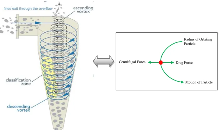
HDPE Particles of fluid bed drying in the gas entering double-cyclone are subjected to centrifugal forces which move them radially outwards, against the inward flow of gas and towards the inside surface of the cyclone on which the solids separate [1]. The performance of cyclone is in a relationship with its static pressure drop between input and output [2]. The factors affecting the rate of entrainment of solids from a fluidized bed dryer named particle size distribution (PSD), terminal velocity, superficial gas velocity, particle density, gas properties and gas flow regime. Therefore, it is necessary to understand the gas-particle flow and separation characteristics of the cyclone.
With computational fluid dynamics (CFD techniques), it is now possible to sufficiently calculate the pressure drop created in cyclone. Fluid flows have been mathematically described by a set of nonlinear and partial differential equations named the continuity and Navier–Stokes equation [3]. ANSYS Fluent solves conservation equations for mass and momentum and additional transport equations are also solved when the flow is turbulent. Different CFD calculation have been successfully applied by employing the related mathematic model to determine the features of gas-solid flow field for cyclones [4, 5]. Turbulence models such RNG-based k-ɛ model which was derived using a statistical technique called renormalization group theory is one of the proper models in this field. In Fluent, the Lagrangian discrete phase based partly on the physical properties of dust particles and partly on the mathematical modeling with reasonable assumptions made to describe the particles transport in a fluid medium [6]. Generally, the pressure drop over a cyclone is a difference of static pressure between the inlet and the outlet. The static pressure at inlet cross- section is uniformly distributed because there is no swirling motion. It can be easily measured with a pressure tapping on the wall. In the past, Stairmand ignored the influence of the swirling flow, of course, it is not precise. Shepherd and Lapple discharged the air directly from the cyclone to atmosphere whereas; the latter two ways have been widely used in investigation and engineering fields [7, 8].
2-
Theoretical Relations
Pressure losses inside the cyclone due to the energy dissipation by the viscous stress of the turbulent rotational flow create the main part of the pressure drop in cyclone about 80% [9]. The remaining 20% of it, caused by the contraction of the fluid flow at the outlet, expansion at the inlet and by fluid friction on the cyclone wall surface.
Tangential inlets are preferred for the separation of solid particles from gases [1, 10]. The static pressure measurement becomes complicated and difficult because of strong swirling flow at the outlet pipe leading to use CFD simulation of cyclone to validate the calculated data with industrial-experimental pressure drop in double- cyclone. According to the Navier-Stokes equations, tangential velocity does not depend on the "Z" coordinate; radial velocity is constant throughout the flow and flow is turbulent [10]. The relationship between pressure and 3D velocity can be simplified by neglecting the axial effects. The centrifugal force FC at radius r is equal to mUθ2/rgc, where m is the mass of the particle and Uθ is its tangential term. A large-diameter cyclone has a much lower separation factor at the same velocity. The calculated performance of the equipment through theoretical relations is concluded using its static pressure drop between input and output and following efficiency expression [11].
∆𝑃𝐶 = 𝜉𝑐
𝜌𝑔𝑉𝑖2
2 (1)
The cyclone pressure drop (ΔPC) is directly related with the square of the velocity (Vi2), resistance coefficient (ξc) and gas (N2) density (ρg) and Euler number (Eu) for the cyclone will be defined based on Equation 2:
𝐸𝑢=
∆𝑃𝐶
1 2 𝜌𝑔𝑉𝑖2
(2)
HDPE Particles in a real powder will seldom be of uniform size but will be characterized by a PSD, which will affect their rheological and fluidization behavior. For example, a wide size distribution has been observed to lead to smoother fluidization and better gas-solid contacting [12], whereas a narrow distribution may enhance bed stability (e.g., reduce segregation)[13]. In addition, the presence of fines (particles of 45μm diameter or less) may improve the performance of fluidized-bed mediums [14, 15]; however, excessive fines may cause the powder to be too cohesive for proper fluidization [16]. Particle size and PSD will influence the magnitude of the interparticle force. As the size distribution increases, the minimum fluidization velocity decreases, while the minimum bubbling velocities increases.
Figure 1. Schematic diagram of cyclone.
Radius of Orbiting Particle
Drag Force
3-
Industrial Experiment
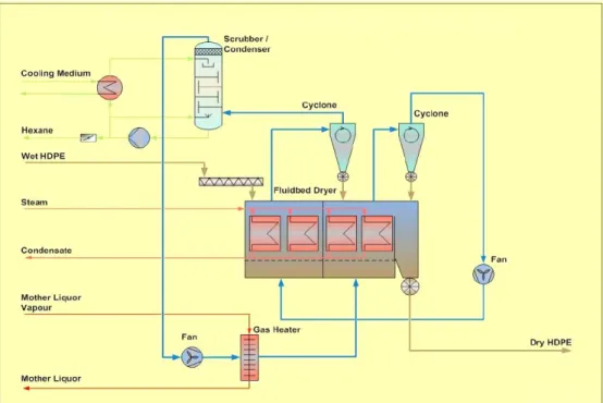
In fluidized bed processes the passage of gas through the bed entrains HDPE fine particles. These particles, based upon Figure 2, must be separated from the gas and returned to the bed for post drying before the gas can be discharged or sent to the next stage in the process. The substances used in this test are wet HDPE (humidity is n-Hexane) and Nitrogen (Table 1). The pre-dried product reaches the second stage where final drying to the required hexane content of 0.1%. The hot exhaust gas of drying stage 2 of approx. 78-80°C is de-dusted in the second cyclone before being recompressed in BL-1 (blower) to be used to flash-dry the wet HDPE coming in the first drying stage to about 1% hexane content (dry basis). Because of the high dust content of the drying gas, the gas distributor has a special slotted plate. The nitrogen gas which is re-circulated from stage 2 is simultaneously loaded with additional hexane which corresponds to about 35% relative humidity. The rich gas will be leaving the first drying stage at approx. 60°C to be de-dusted in the first cyclone then, the gas must be regenerated by condensing the hexane that has been evaporated in the dryer by using scrubbing tower. High dust loadings can be handled, and hence cyclones can be used to separate flash-dried particles from the gas leaving the dryer [10]. The double-cyclones consist of the spiral hood, cylinder, cone and triangular dust hopper that secondary gas streams from the pressurized dryer back to the dust hopper are prevented by means of the rotary valves which do also control / even out the dust flow rate from the hoppers back into the dryer. A level indicator controls the dust level in the hopper.
Figure 2. Industrial fluid bed dryer and double-cyclone for drying process.
The performance of cyclone is indicated by means of the controlling devices on the feed flow rate, the volumetric gas flow rate, temperature, pressure and pressure drop has been installed in this industrial test method. In the experimental procedure, PE100 as one of the most commonly polymeric grades has been used. We determined the pressure drop deference versus the volumetric gas flow rate at the operating temperature, pressure, wet polymeric feed rate, particle size distribution and density.
Table 1. Physical properties of industrial materials.
Descriptions ρ(kg m-3) μ (kg m-1s- 1)
Nitrogen (N2) 1.251 2.07×10⁻⁵
Normal hexane (HX) 659 3×10⁻⁴
PE100 (based on ZN -Catalyst) 948±0.002 -
Table 2. Particle size distribution (PSD) for PE100 as HDPE grade.
Size (µm) volume (%)
450 2.98
357.5 7.9
282.5 7.31
225 32.51
180 24.36
142.5 16.32
94 5.32
63 3.3
Table 3. Industrial results of double-cyclone versus nitrogen flow rate in PE100 with wet feed rate of 38000 kg hr -1.
N2 flow rate (m3hr -1) PDI (kPa) Volatile (%)
13981 2.0215 0.08
14040 2.0375 0.04
14060 2.0395 0.05
4-
CFD Calculations
ANSYS FLUENT 15.1 is a commercially available CFD code that utilizes the finite volume formulation to carry out coupled or segregated calculations (with reference to the conservation of mass, momentum and energy equations). It is ideally suited for incompressible to mildly compressible flows such the present process. The conservation of mass, momentum and energy in a fluid flow are expressed in terms of non-linear partial differential equations that usually defy solution by analytical means.
4-1- Computational Mesh-Grid Generation
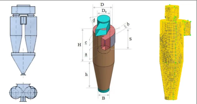
Figure 3 schematically illustrates the single section of double-cyclone geometries and grid arrangement. The cyclones are meshed by the tetrahedral grids, and divided by the coarse, moderate and fine grids, respectively. Based on the grid division, the final computational domain is divided finally by unstructured grid, contains 390000 control mesh cells [17, 18].
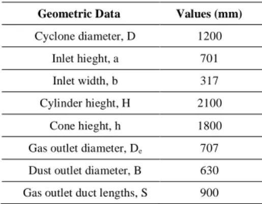
Table 4. Cyclone geometry used in this simulation.
Geometric Data Values (mm)
Cyclone diameter, D 1200
Inlet hieght, a 701
Inlet width, b 317
Cylinder hieght, H 2100
Cone hieght, h 1800
Gas outlet diameter, De 707
Dust outlet diameter, B 630
Figure 3. Industrial cyclone geometry and grid of cyclone.
4-2-Solution Algorithm
For the turbulent flow in a double-cyclone, the proper key to the success of CFD lies with the accurate description of the turbulent behavior of the flow [19]. Turbulence may be stabilized or destabilized in the parts of flow domain where strong streamline curvature is present. For modeling the swirling turbulent flow in a cyclone separator like HDPE double-cyclone, there are numerous turbulence models available in Fluent such as standard k- ɛ, RNG k-ɛ to the more complicated Reynolds stress model (RSM).
The k-ɛ model involves the solution of transport phenomena equations for the kinetic energy of turbulence and its dissipation rate and the calculation of a turbulent contribution to the viscosity at each computational cell. However, to reduce the computational effort, the RNG k-ɛ model can be used with about 10-12% deviation on industrial-experimental data [19]. The finite volume method has been used to discretize the partial differential equations of the model using the PISO algorithm performs two additional corrections: neighbour correction and skewness correction for improving the efficiency of numerical simulation by repeating calculation until the balance is satisfied [20, 21]. This method is used for pressure-velocity coupling and the scheme to interpolate the variables on the surface of the control volume in cyclone section.
4-3-Boundary Conditions and Convergence
Pressure inlet boundary condition at inlet, pressure outlet at gas outlet and wall (no-slip) boundary condition at all other boundaries are used. Moreover, in particle phase conditions, to calculate the trajectories of the particles, it was necessary to give information regarding the starting position and physical state of the particle.
Convergence of numerical simulation faced difficulties however was resolved with suitable under-relaxation factors. Marching of discretized equation on control volume grid points needs to good initial estimate for faster convergence. The values for turbulence intensity and length scale are critical and carefully assigned for inlet boundary conditions.
5-
Result and Discussions
According to the theoretical-experimental analysis of double-cyclone in HDPE fluid bed drying, it is obvious that
pressure drop in cyclone is in association with gas velocity, particle density, particle size distribution and all results achieved from industrial experiments are in good agreement with theoretical concept of pressure losses happened in cyclone.
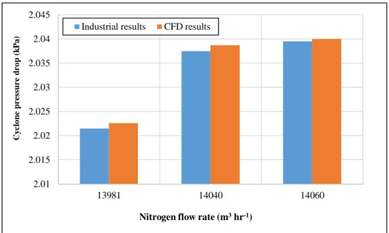
The values of pressure drop in various nitrogen flow rates have been shown in table 3, which indicate rightly the acceptable drying conditions and operating parameters. Although high pressure drop in double-cyclone represents the effective performance of HDPE separation in the process, optimum value of that will conclude the suitable conditions for drying.
Figure 4.3D map contours of static pressure (Pa) at PE100 with 14040 m3hr -1 N2 flow rate.
Contours of static pressure and pressure drop which have been calculated in the present CFD indicate clearly that fluidized bed hydrodynamic behavior is very important and must be controlled to improve fluidized bed operations. One of the effective- operating parameters which affect the fluidized regime is nitrogen flow rate that all resuls as shown in theoreticlal relations, experimental data and CFD calculations will be in acceptable agreement with each other and create the operating conditions to produce HDPE powdery product with optimal volatile.
Figure 5. 2D map cyclone pressure drop versus N2 flow rate at PE100.
2.01 2.015 2.02 2.025 2.03 2.035 2.04 2.045
13981 14040 14060
C
y
c
lo
n
e
p
r
e
ss
u
r
e
d
r
o
p
(k
P
a
)
Theoretical relationship
mUθ2/rgc ∆PC = ζCρgVi2/2 Eu = ∆PC / (0.5 ρgVi2)
Industrial-experiments
Nitrogen flow rate Cyclone pressure drop
Volatile of powder
CFD results
Pressure contours Calculated pressure drop
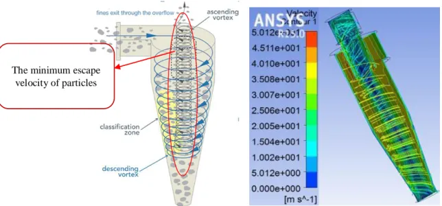
Particles trajectory Figure 6.3D map contours of velocity (m s-1) at PE100 with N2 flow rate of 14040 m3hr -1.
Based on HDPE particles trajectory in double-cyclone both in theoretical figure 1 and simulated domains, separation of dusts from gas entering the cyclone is in the good condition. Minimum dusts are visible in ascending vortex whereas, sight visit validate this industrial-basic issue.
Figure 6 obviously illustrates the minimum calculated velocity in ascending vortex section representing the low escape of HDPE particulates in outer vortex area. The effective separation factor of the cyclone will be present in this condition.
10. Conclusion
Double-cyclone as a separation device is an essential equipment of HDPE fluidized bed drying. Fluid bed dryer to prepare PE100 particles in dry situation need the best condition which will be connected to related nitrogen flow rate, cyclone pressure drop and volatile of product. The suitable strategy to study the double-cyclone for improving the performance of operation will be based on Figure 7.
Figure 7. Schematicofstudy in double-cyclone.
This proper strategy dictate the sufficient gas flow rate of 14040 m3hr -1 for drying of PE100 polymer to create 0.04% volatile in dry product with cyclone pressure drop of 2.0375 kpa, which reflects the optimal conditions of drying in HDPE slurry process. Therefore, pressure drop of the cyclones is an effective parameter represents the drying behavior. Geometry of cyclone, inlet flow rate of gas, density and particle size distribution (PSD) are very important to the study because CFD study in industrial double-cyclone with these information will be able to simulate fluid flow and solid particulates in the cyclone domain.
6-
References
[1] Altmeyer, S., V. Mathieu, S. Jullemier, P. Contal, N. Midoux, S. Rode, and J.-P. Leclerc. “Comparison of Different Models of The minimum escape
an industrial double-cyclone of HDPE fluidized bed drying. The 9th International Chemical Engineering Congress & Exhibition, Iran, (2015).
[3] Zhao, B., Y. Su, and J. Zhang. “Simulation of Gas Flow Pattern and Separation Efficiency in Cyclone with Conventional Single and Spiral Double Inlet Configuration.” Chemical Engineering Research and Design 84, no. 12 (December 2006): 1158–1165. doi:10.1205/cherd06040.
[4] Bernardo, S., M. Mori, A.P. Peres, and R.P. Dionísio. “3-D Computational Fluid Dynamics for Gas and Gas-Particle Flows in a Cyclone with Different Inlet Section Angles.” Powder Technology 162, no. 3 (March 2006): 190–200. doi:10.1016/j.powtec.2005.11.007.
[5] Zhou, L.X., and S.L. Soo. “Gas—solid Flow and Collection of Solids in a Cyclone Separator.” Powder Technology 63, no. 1 (October 1990): 45–53. doi:10.1016/0032-5910(90)80006-k.
[6] Jayaraju, S. T. "Study of the air flow and aerosol transport in the human upper airway using LES and DES methodology." PhD diss., Ph. D. thesis, Vrije Universiteit Brussel, 2009.
[7] Stairmand, C. J_. "The design and performance of cyclone separators." Trans. Instn. Chem. Engrs. 29 (1951): 356-383. [8] Shephered, C. B., and C. E. Lapple. “Flow Pattern and Pressure Drop in Cyclone Dust Collectors.” Industrial & Engineering
Chemistry 31, no. 8 (August 1939): 972–984. doi:10.1021/ie50356a012.
[9] Ogawa, A. Separation of particles from air and gasses. vols. 1 and 2, CRC Press, Boca Raton, Florida, USA, (1984). [10] van’t Land, C.M. Drying in the process industry. John Wiley & Sons, Hoboken, New Jersey, (2012).
[11] McCabe, Warren Lee, Julian Cleveland Smith, and Peter Harriott. Unit operations of chemical engineering. Vol. 5. New York: McGraw-Hill, 1993.
[12] Grace, J. R., and G. Sun. “Influence of Particle Size Distribution on the Performance of Fluidized Bed Reactors.” The Canadian Journal of Chemical Engineering 69, no. 5 (October 1991): 1126–1134. doi:10.1002/cjce.5450690512.
[13] Gauthier, D., S. Zerguerras, and G. Flamant. “Influence of the Particle Size Distribution of Powders on the Velocities of Minimum and Complete Fluidization.” Chemical Engineering Journal 74, no. 3 (July 1999): 181–196. doi:10.1016/s1385-8947(99)00075-3.
[14] Pell, M. "Effect of fines and velocity on fluid bed reactor performance." In AIChE Symp. Ser., vol. 184, no. 262, pp. 68-73. 1988.
[15] Yates, J.G., and D. Newton. “Fine Particle Effects in a Fluidized-Bed Reactor.” Chemical Engineering Science 41, no. 4 (1986): 801–806. doi:10.1016/0009-2509(86)87160-3.
[16] Geldart, D. “The Effect of Particle Size and Size Distribution on the Behaviour of Gas-Fluidised Beds.” Powder Technology 6, no. 4 (October 1972): 201–215. doi:10.1016/0032-5910(72)83014-6.
[17] Thompson, Joe F., Zahir UA Warsi, and C. Wayne Mastin. Numerical grid generation: foundations and applications. Vol. 45. Amsterdam: North-holland, 1985.
[18] ICEM/CFD hexa manual documentation, ICEM CFD, engineering, GMBH. (1998).
[19] Griffiths, W.D., and F. Boysan. “Computational Fluid Dynamics (CFD) and Empirical Modelling of the Performance of a Number of Cyclone Samplers.” Journal of Aerosol Science 27, no. 2 (March 1996): 281–304. doi:10.1016/0021-8502(95)00549-8.
[20] ANSYS Fluent Theory Guide. (2008). Inc.