TECHNICAL UNIVERSITY OF CLUJ-NAPOCA
ACTA TECHNICA NAPOCENSIS
Series: Applied Mathematics, Mechanics, and Engineering Vol. 61, Issue Special, September, 2018
SAFETY MANAGEMENT WITHIN A ROBOTIC MANUFACTURING
SYSTEM THROUGH LAYOUT DESIGN
Bogdan MOCAN, Stelian BRAD, Mircea FULEA, Mircea MURAR, Emilia BRAD
Abstract: Nowadays manufacturing systems have been increasingly becoming more complex and flexible to respond to market changes. Previous studies treated Facility Layout Problem (FLP) as an optimization problem to achieve high performance. However, the optimization problem does not adequately cover all the issues regarding risk/safety analysis. Risk factors such as the dangers of falling objects, noise pollution and assuring the optimum maintenance tasks within a robotic manufacturing system tend to be neglected. Moreover, when managers face different facility layout scenarios, no safety risk assessment models are currently available to help them make the right decision. Therefore, this paper proposed a new methodology for solving the FLP within a robotic manufacturing system based on a risk assessment model, including factors identification and investigation, and safety zones determination by layout analysis. The proposed methodology helps designers to generate the production facility layouts that enable high performance in safe conditions, assure manual maintenance interventions and help site managers to evaluate different site layout scenarios much easier and more accurately. Finally, a case study is used to verify the proposed methodology. The developed case study highlights the layout design of a robotic line for depalletizing that takes into consideration the safety and productivity concerns specific to furniture plants. This case study interprets how to implement manufacturing safety management by means of facility layout improvement. The findings contribute to a safety efficient management on a manufacturing facility by properly equipment arrangement in the design stage and, in turn, guaranteeing the safety production.
Key words: Facility Layout Design, Safety Zones, Robotic Production Plant, Safety Management.
1. INTRODUCTION
Manufacturers want to introduce new products regularly and with minimum disruption of manufacturing facility layout. Managers often cope with the inefficiencies of existing layouts with limited and localized fixes rather than undergo expensive, complicated and time-consuming layout redesign. Emerging trends in industry which influence production layout include: delayed product differentiation, scalable machines, movable machines, and distributed and modular layouts [1].
Owing to these concurrent needs, along with the lack of industrially viable engineering tools, the design of production facility layout in general, or robotic work-cells specially is currently tackled with a trial-and-error approach mostly based on the designer
experience, while the safety performance is usually neglected and verified only during the final commissioning. On the other hand, even if the industrial design practice has been somehow unreceptive to the academic researches, the problem of finding the best industrial robots location with respect to an assigned task has been investigated since the late 80s [2]. Manufacturing facility layout generation and evaluation is challenging and time consuming due to its multi-objective nature and requires extensive data collection,
analysis and synthesis. Layout safety
researchers to manufacturing system configuration in many fields [4], systems layout safety has not been given much consideration. In reference [5] is revealed that 46.8% of accidents are related to the design chosen for safety and that certain risks can be avoided by making minor changes to a layout design.
Thus, more attention must be paid to safety planning in the design phase to improve safety management more effectively. Previously, safety researchers tended to conduct safety management during the implementation phase and emphasized the important roles that risk
factors play in safety performance
improvement. These researchers discovered that most accidents are related to inadequate hazard recognition or appraisal and thus are rarely mitigated [6]
This paper proposed a new methodology for solving the Facility Layout Problem within a robotic manufacturing system based on a risk
assessment model, including factors
identification and analysis, and tasks zones determination by layout analysis. The proposed methodology will help designers to generate much easier the production facility layouts that enable high performance in safe conditions, assure manual maintenance interventions and help site managers to evaluate different site
layout scenarios more accurately and
holistically. Finally, a case study has been developed to verify the proposed methodology. The developed case study highlights the layout design of a robotic line for depalletizing that takes into consideration the safety and productivity concerns specific to furniture plants. This case study interprets how to implement site safety management by means of facility layout improvement. The findings contribute to a safety efficient management on a manufacturing facility by properly equipment arrangement in the design stage and, in turn, guaranteeing the safety production.
2. THEORETICAL BACKGROUND AND RELATED WORK
A manufacturing system configuration or layout is the set of constituent components,
such as industrial robots, machines,
workstations, transporters and conveyors, etc.,
and the number and type of each module that make up a manufacturing system and their relationships which define the flow of work pieces between them [7]. The layout design significantly effects the balancing of workload and occurrence of bottlenecks among manufacturing operations [6]. Thus, layout design plays a determinant role in proper working and smooth running of the hole manufacturing system.
Robotic manufacturing systems designers are required to carry out risk assessments and implement protective measures for all phases of the robotic systems life cycle. Accident reports show that workers are injured and killed by
robots or other machineries during
interventions other than production, such as setting, teaching, process changeover, fault-finding, cleaning or maintenance. One of the most important design feature in manufacturing systems implies to provide the necessary safety for those interventions.
To understand very clearly what we mean by safety within a manufacturing system, first we need to define the specific safety terminology, as follow: Failure: an event where a system or subsystem component does not exhibit the expected external behaviour and environmental conditions under which it must be exhibited should be documented in the requirements specification [8]. Error: an incorrect internal system state [8]. Mishap: is an unplanned event or series of events resulting in death, injury, occupational illness, or damage to or loss of equipment or property or damage to the environment [9]. Hazard: a system state that might, under certain environmental conditions, lead to a mishap [8] Hence hazard is a potentially dangerous situation. Risk: is the combination of the possibility of an abnormal event or failure, and the consequence(s) of that event or failure to a system’s components, operators, users or environment [9]. Safe: is having acceptable risk of the occurrence of a hazard [9]. Safety: is the freedom from those conditions that can cause death, injury, occupational illness, or damage to or loss of equipment or property [10]. System Safety: application of engineering and management principles to optimize safety and reduce risks
effectiveness, time and cost throughout all phases of the system life cycle [10].
A Safety Critical System is such a system which has the potential and may cause accidents either directly or indirectly. Failure of such systems can result in loss of life, property damage, environmental harm and financial loss. Safety is dependent on proper operations of such systems. Safety is always considered to the whole system including all safety critical operations. Some examples of Safety Critical
Systems are Production Industries –
Production, Manufacturing Controls,
Maintenance and use of Robots.
Safety automation greatly depends on
appropriate hazard analysis and risk
assessment. Automation is transformation to smart, safe and sustainable emergence of profound changes for safety optimization.
Automation technology utilizes safety
controllers, programmable logic controllers (PLC), safety sensors, and design guarding systems to meet safety requirements. Risk assessment identifies potential hazards to reduce the risk and increase productivity. Automation addresses setup, operation and maintenance tasks combined with equipment or work environment and makes use of task-based analysis by reviewing incidence reports. Moreover, identifies additional risks and assign risk ranking with the involvement of operational safety specialty expert. Facilitates in reporting scope of risk, overview of safety-critical operations and assign risk category and ensure evidence of probable risk. Currently there are several ISO standards (i.e. ISO 12100:2010; ISO 11161:2007; ISO
10218-1:2011; ISO 10218-2:2011), technical
specifications or local regulations that generate the framework for risk assessment within a robotic manufacturing facility.
Certainly, one of the most challenging tasks in safety science today is to develop ways of assessing industrial manufacturing systems in order to capture the patterns identified by social sciences following different accidents, to prevent them from causing disasters. In other words, the challenge is to develop ways to better grasp in foresight what is being interpreted in hindsight.
Regarding the facility layout problem this is a fundamental problem which seeks to reduce material handling costs, work in process, lead times, utilize existing space more effectively, make plant adaptive to future changes, provide a healthy, convenient and safe environment for employees, and generally increase productivity through determining an efficient arrangement (layout) of the required facilities within the organization [4,6,7,13].
In terms of computational complexity, the FLP is categorized into NP-complete class [14]. This problem has been studied for a long time and has a rich literature. A variety of review papers have been published to analyse and summarize the relevant research [15,16,17,18].
The first issue that should be considered to model any facility layout problem is to make a decision whether it is dynamic or static. In the dynamic state, the flow between departments may change over time. Therefore, the planning horizon is divided into some periods (weeks, months, years, etc.) and a layout is specified for each period, by adopting this assumption that the required data are fixed during the intended period. On the other hand, in the static state, all data and information would remain fixed over time, and so there is only one layout instead of a sequence of layouts [15,16].
Departments and floors, which are the main components of any FLP, can be viewed from two aspects of shape and dimension. Shape can be regular (i.e. rectangular) or irregular.
Formulation of facility layout problems, in a general view, can be divided into two
approaches: discrete and continuous
formulation. The solution space of the problem would be limited by employing the first formulation manner; but on the other hand, constructing irregular shapes is possible here. While in continuous formulations, only regular shapes could be achieved. Advantages, disadvantage, and applications of these two methods can be found in references [20,22].
blocks related to each department can be handled through mathematical programming models [19,21], which require extremely high computational efforts.
Therefore, designing a layout for a manufacturing environment strongly depends on the type of manufacturing system, specific conditions, local cultural environment, etc. Lack of attention to this key characteristic may lead to a layout which does not meet the requirements. The manufacturing system also affects the decisions related to the flow of materials and products. Involving the above considerations can impose uncertainty on the problem. The uncertainty level should be managed by good safety measures implemented within the facility.
3. THE PROBLEM
From the above arguments, one should be able to understand the complexity of solving the facility layout problem within a manufacturing facility. Also, it has to be notice that there are plenty of researches on this topic, but the achievements aren’t so practical relevant because implies a lot of time to make the calculus and requires knowledge from various fields to successfully complete this process.
In practice the design of production facility layout is currently tackled with a trial-and-error approach mostly based on the designer experience, while the safety performance is usually neglected and verified only during the final commissioning to the client. More in the current approaches there is nothing said about safety zones, that is about developing the facility layout according to the task(s) zones. Development of production plant considering the safety zones involves segregating the plant into task zones, which could be disconnected from the system, where personnel can perform their tasks in safety condition.
4. METHODOLOGY
The main objective of this paper is to propose a new method for solving the FLP within a robotic manufacturing system based on a risk assessment model, including safety zones
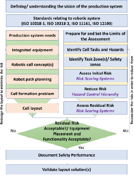
determination by layout analysis. The proposed methodology helps designers to generate much easier the production facility layout(s) that enable high performance in safe conditions, assuring zone segregation (ex. manual maintenance interventions) and helping site managers to evaluate different facility layout scenarios more accurately. The proposed approach is transferred into a consistent methodology oriented on easy practical implementation, and it consists of several phases highlighted in Figure 1. Each methodology phase contains one or more steps.
First phase of the proposed methodology is to define/ understand the vision of the production system: implies the analysis/ evaluation of the existing production system facility by the point of view of geometrical characteristics, production volume, process turbulences and part’s scheduling, safety zones as well as the transferring and handling costs; for a completely new production system this phase facilitate the production goals’ definition and identification of available space and the layout geometrical constrains. This step should, also, identify the major weaknesses of an existing production system addressing the cell performance. This evaluation step is an important part of the methodology because it defines and focuses the scope of the effort. Furthermore, this phase of the methodology involves the determination of the root causes of deviation from an optimised production system of an existing manufacturing system or to define the production needs for a completely new robotic manufacturing system.
The methodology is further developed so that new layout solution(s) is generated and risk assessment limits are set. The layout of the work-cell is critical to mitigate the risk of hazards, to achieve an acceptable residual risk and to establish the optimum production flux where all required equipment is to be integrated. The equipment includes the robot,
part/material conveyors or feeders as well as additional integrated machinery. At this point it is necessary, also, to set the limits of the assessment and to identify manufacturing cell tasks and hazards. This phase also identifies workplace health and safety legislation, codes of practice and published technical standards.
Figure 1. Phases of the proposed methodology
Next phase is to identify tasks zone(s) of the automation manufacturing system. A zone may include space within or around the manufacturing system, which is used by personnel to access a specific location, an operating position or a servicing point or in which personnel perform standard production operations or other tasks (e.g. maintenance).
Automation manufacturing systems should be designed to facilitate safe manual
problem(s). In the acceptation of this paper a task is a specific activity performed by one or more machines or persons on, or in the vicinity of, the machine during its life cycle.
Regarding the robotic manufacturing systems, the facility layout can be generated considering the robot facility by which the reach of a robot can be limited beyond the robotic workspace using both mechanical and software-based solutions.
Depending on the robot manufacturer one or more axis can be limited using mechanical stops and this will ensure that even under manual mode, the robot reach is limited. Through software, it is also possible to specify the robot workspace which must include the collaborative workspace. When deciding on the layout, access for operational activities such as
material/part feeding and evacuation,
maintenance operation etc., needs to be considered. Additional risks are introduced due to these operational requirements and the effects of these hazards needs to be mitigated.
The starting point of the risk analysis is an already exists manufacturing layout or a new generated layout facility by design. A manufacturing layout requires analyses of various requirements such as productivity (e.g.: task sequence and allocation, ergonomics), coordination with upstream and downstream work-cells, workforce and material planning etc., which will not be taken into account in this article.
Initial risk level identified during the risk analysis, which is the next phase of the methodology, needs to be reduced by applying one or more risk reduction measures, like [23]: Elimination (i.e., try to eliminate the hazard); Substitution (i.e., try to substitute the identified hazard with a smaller hazard);
Limit interaction (i.e., reduce or eliminate interaction between the hazard and the person); Safeguarding (i.e., Safeguards and Safety-Related Parts of the Control System);
Complementary Protective Measures (i.e., measures that may reduce the severity of injury, such as emergency stops, enabling devices, and energy isolation);
Information for Use (i.e., Warnings and Awareness Means, Administrative Controls);
According to [23], neither Complementary Protective Measures nor Information for Use may be used until or unless the risk level is or has been reduced to LOW or NEGLIGIBLE. Risk is the combination of the possibility of occurrence of an abnormal event or failure, and the consequence(s) of that event or failure to a system’s components, operators, users or environment.
According to [23] risk is determined by three criteria (Figure 2):
Injury Severity is a function of the degree of estimated damage due to each hazard while a person is performing a task. Severity has three rankings: S3 (Serious), S2 (Moderate), and S1 (Minor).
Exposure is a function of the estimated incidence of exposure (either frequency or duration) to the hazard. Exposure has three rankings: E2 (High), E1 (Low), and E0 (Prevented).
Avoidance is an assessment of a person’s ability to sense and avoid a hazardous situation. Avoidance has three rankings: A3 (Not possible), A2 (Not likely), and A1 (Likely). Therefore, design of the facility layout needs to consider the situational awareness of the operator and change of mode of the robot during risk assessment. Tools to complement situational awareness are warning lamps, floor markings, timer etc. and can also be used to convey mode change of the robot. In addition, buttons and enabling devices can be used to trigger mode-change of the robot status.
The facility layout evaluation is iterative until the residual risk level is acceptable, the
equipment functionality and machinery
placement are, also, acceptable. It practically falls within the assessment limits set at the initiation of the methodology.
Finally, the methodology involves
documentation the safety performance of the generated or redesigned layout and validation the layout solution(s). This is the final phase of the methodology.
Thus, the proposed methodology is an iterative process that facilitates the achievement
of the desired productivity in the
Figure 2. Risk assessment according to TR R15.306 [23].
To verify the proposed methodology a case study was developed within the next section.
5. CASE STUDY – ROBOTISED
DEPALLETIZING MANUFACTURING
SYSTEM
The developed case study highlights the layout design of a robotic line for depalletizing and pallets forming that take into consideration the safety and productivity concerns specific to furniture manufacturing facility. This case study interprets how to implement site safety management by means of facility layout improvement. The findings contribute to a
safety efficient management on a
manufacturing facility by properly equipment arrangement in the design stage and, in turn, guaranteeing safety production.
The safe design of a robotic manufacturing plant based on the proposed methodology is a repetitive process. After the initial control measures are incorporated into the design, the design should be reviewed to determine whether there are remaining risks and whether redesign can eliminate or minimise these risks. Within the robotic cell (Figure 3) there are several tasks to accomplish the depalletizing
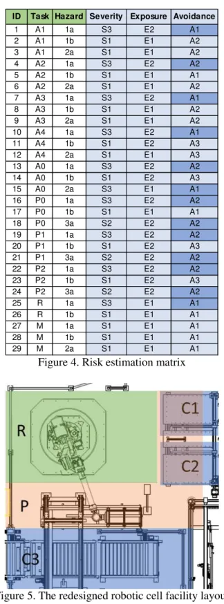
and pallets forming activities. Based on the risk assessment rank [23] (Figure 2) there are the following tasks and exposure to hazards: A1, A2, A3, A4 – loads/unloads cardboard sheet (Exposure to hazard - E2); R – teaching the robot (E1); A0, P1, P2 – jam clearing (E2); M - Conveyors, feeders and robot maintenance (E1).
Figure 3. The evaluated robotic cell layout.
Next step was to identify the hazard sources, which were the followings: 1. Robot/End Effector; and 2. Conveyors and hazards types, were: robot/end effector (S3) – 1a: crushing, 1b: dropped parts; conveyors A1, A2, A3, A4 (S3) – 2a: in-running nip points; conveyors P0, P1, P2 (S2) – 3a: in-running nip points; conveyor A0 (S3) - 3a: in-running nip points.
In figure 3, the overview of the production facility, there are eight task zones: A1, A2, A3, A4 are the zones for cardboard sheet feeding, and A0 task zone is the zone for finalised products loading. The cardboard sheet place zone is P0 conveyor and the two zones P1, P2 are for pallets placing. The pallets conveyor (P1, P2 task zones) is the infeed for other manufacturing process within the same plant. The entire manufacturing cell have to be maintained, so task zone M is for maintenance activities which must serve all task areas.
made, and the results are presented in Figure 4 (based on approach promoted within the reference [23]).
ID Task Hazard Severity Exposure Avoidance
1 A1 1a S3 E2 A1
2 A1 1b S1 E1 A2
3 A1 2a S1 E1 A2
4 A2 1a S3 E2 A2
5 A2 1b S1 E1 A1
6 A2 2a S1 E1 A2
7 A3 1a S3 E2 A1
8 A3 1b S1 E1 A2
9 A3 2a S1 E1 A2
10 A4 1a S3 E2 A1
11 A4 1b S1 E2 A3
12 A4 2a S1 E1 A3
13 A0 1a S3 E2 A2
14 A0 1b S1 E2 A3
15 A0 2a S3 E1 A1
16 P0 1a S3 E2 A2
17 P0 1b S1 E1 A1
18 P0 3a S2 E2 A2
19 P1 1a S3 E2 A2
20 P1 1b S1 E2 A3
21 P1 3a S2 E2 A2
22 P2 1a S3 E2 A2
23 P2 1b S1 E2 A3
24 P2 3a S2 E2 A2
25 R 1a S3 E1 A1
26 R 1b S1 E1 A1
27 M 1a S1 E1 A1
28 M 1b S1 E1 A1
29 M 2a S1 E1 A1
Figure 4. Risk estimation matrix
Figure 5. The redesigned robotic cell facility layout – based on proposed methodology.
Based on the obtained risk estimation results (Figure 4) and applying the proposed methodology the layout generation process was
resume by trying to reduce the risk level and intended to segregate the layout into safety zones. After several iterations the result shown in the figure 5 was obtained. The cell layout complexity has been reduced, the amplitude of the robot movements was diminished with direct effects on productivity growth, and the cell modularity and segregation has been increased. The cardboard sheet feeding has been merged to a single conveyor - C1 zone, C3 zone has been dedicated for pallets placing, and C2 zone has been redesigned for finalised products loading.
The main advantage of the new layout is that the safety zones are well-defined as tasks zones and they can be switched off and disconnected from the controller in situations where it is needed (i.e. maintenance, evaluations etc.).
6. CONCLUSIONS
The proposed methodology facilitates getting straight to a correct result like new or redesign production facility layout without using complicated approaches or complex mathematical formalisms and give to the user documented evidence of safe automated operations within robotic cells. Also, it helps site managers to evaluate different site layout scenarios. The framework provides information to identify cell task(s) and hazards, risks, and safety zone(s).
Proposed methodology can be adapted for any industrial field. This work can be further extended to address implementation costs and time. Rigorous work is needed to meet the complete set of safety automation requirements leading to standardization of the methodology. The proposed methodology provides a framework for generate a robotic facility layout while delivers clarity to improve safety for operators, environment, equipment, identified hazards and regulatory compliance.
7. ACKNOWLEDGMENTS
The staff of the Laboratory for Robotization Manufacturing at the Technical University of Cluj-Napoca are gratefully thanked for making this research possible.
8. REFERENCES
[1.] Benjaafar, S, Heragu, S.S., Irani, S.A.,
Next generation factory layouts: research challenges and recent progress. Interfaces;
Vol. 32, No. 6, pp. 58–76, (2002).
[2.] Meller, R.D., and Gau, K.Y., The facility layout problem: Recent and emerging trends and perspectives, J. Manuf. Syst., Vol. 15,
No. 5, pp.351–366, (1996).
[3.] Hasan, M.A., Sarkis, J., Shankar, R.,
Agility and production flow layouts: an analytical decision analysis, Computers and
Industrial Engineering; Vol. 62, No. 4, pp. 898–907, (2012).
[4.] Mocan B., Buna D., Fulea M., Brad S.,
Increasing the efficiency of robotic manufacturing systems by layout optimization, Applied Mechanics and
Materials - Mechatronics and Robotics, Vol. 762, Trans Tech Publications, pp. 283-290, (2015).
[5.] Malekitabar, H., Ardeshir, A., Sebt, M.H., Stouffs, R., Construction safety risk drivers: a BIM approach., Safety Science,
Vol. 82, pp. 445-455, (2016).
[6.] Albert, A., Hallowell, M.R., Skaggs, M., Kleiner, B., Empirical measurement and improvement of hazard recognition skill.
Safety Science, Vol. 93, pp. 1–8, (2017). [7.] Mocan, B., Fulea, M., Brad, E. and Brad,
S., State-of-the-Art and Proposals on Reducing Energy Consumption in the Case of Industrial Robotic Systems, Proceedings
of the 2014 International Conference on Production Research – Regional Conference Africa, Europe and the Middle East; 3rd International Conference on Quality and Innovation in Engineering and Management, Cluj-Napoca, Romania, 1-5 July, pp. 328-334, (2014).
[8.] Leveson, N., A new accident model for engineering safer systems. Safety Science,
pp. 237–270, (2004).
[9.] ISO 12100:2010 - Safety of machinery --
General principles for design -- Risk assessment and risk reduction, International Organization for Standardization, (2010). [10.] ISO 11161:2007 Safety of machinery --
Integrated manufacturing systems -- Basic requirements, International Organization for Standardization, (2007)
[11.] ISO 10218-1:2011 Robots and robotic devices -- Safety requirements for industrial
robots -- Part 1: Robots, International Organization for Standardization, (2011). [12.] ISO 10218-2:2011 Robots and robotic
devices -- Safety requirements for industrial
robots -- Part 2: Robot systems and integration, International Organization for Standardization, (2011).
[13.] Mocan, B., Fulea, M., Olaru, M. and
Buchmüller, M., From Intuitive
Programming of Robotic Systems to Business Sustainability of Manufacturing SMEs. Amfiteatru Economic, Vol. 18, No
41, pp. 215-231,( 2016).
[14.] Funke, J., Hougardy, S., & Schneider, J.,
An exact algorithm for wirelength optimal placements in VLSI design. Integration, the
VLSI Journal, Vol. 52, pp. 355–366, (2016). [15.] Balakrishnan, J., & Cheng, C. H.,
Dynamic layout algorithms: a state-of-the art survey. Omega, Vol. 26, No 4, pp. 507–
521, (1998).
[16.] Drira, A., Pierreval, H., & Hajri-Gabouj, S., Facility layout problems: A survey.
Annual Reviews in Control, Vol. 31, No 2, pp. 255–267, (2007).
[17.] Hungerländer, P., & Rendl, F., A computational study and survey of methods for the single-row facility layout problem.
Computational Optimization and
Applications, Vol. 55, No 1, pp. 1–20, (2013).
[18.] Huang, C., & Wong, C., Optimisation of site layout planning for multiple construction stages with safety considerations and requirements.
[19.] Saravanan, M., & Kumar, S. G., Design and optimisation of loop layout problems flexible manufacturing system using sheep flock heredity algorithm. The International
Journal of Advanced Manufacturing
Technology, Vol. 77, No 9–12, pp. 1851– 1866, (2015).
[20.] Singh, S., & Sharma, R., A review of different approaches to the facility layout problems. The International Journal of
Advanced Manufacturing Technology, Vol. 30, No 5–6, pp. 425–433, (2006).
[21.] Huang, C., & Wong, C., Optimisation of site layout planning for multiple
construction stages with safety considerations and requirements.
Automation in Construction, Vol. 53, pp. 58–68, (2015).
[22.] Chen, P., Rohatg, P., Keser, C., Fuzzy
Multi – Level Security : An Experiment on Quantified Risk – Adaptive Access Control.
2007 IEEE Symposium on Security and Privacy (SP’07), pp.222–227, (2007).
[23.] RIA TR R15.306 - Technical Report for Industrial Robots and Robot Systems - Safety Requirements - Task-based Risk Assessment Methodology, Robotics Industry Association
(RIA) published, (2016).
Gestionarea siguranței în cadrul unui sistem de fabricație robotizat prin proiectarea amplasării utilajelor
Rezumat: În prezent, sistemele de producție devin din ce în ce mai complexe și mai flexibile pentru a răspunde la schimbările din piață. Studiile anterioare au tratat Problema Amplasării Utilajelor (eng. Facility Layout Problem (FLP)) ca o problemă de optimizare pentru a obține performanțe ridicate ale facilității de producție. Cu toate acestea, problema de optimizare nu acoperă în mod adecvat toate aspectele legate de analiza riscurilor și asigurarea siguranței în exploatare. Factorii de risc, cum ar fi pericolele căderii obiectelor, poluarea fonicăși asigurarea nevoilor de întreținere într-un sistem de fabricare robotizată, tind să fie neglijate. Mai mult, atunci când managerii trebuie să evalueze diverse scenarii de amplasare a utilajelor, în prezent, nu sunt disponibile metode/modalități care să-i ajute să ia decizia corectă, în ceea ce privește evaluarea riscului rezidual și al nivelului siguranței în exploatare. Prin urmare, această lucrare propune o nouă metodologie pentru rezolvarea Problemei Amplasării Utilajelor în cadrul unui sistem de fabricare robotizat, bazat pe un model de evaluare a riscurilor, inclusiv identificarea și investigarea factorilor de risc și determinarea zonelor de siguranță prin analiza amplasamentului. Metodologia propusă îi ajută pe proiectanți să genereze facilități de producție care să permită performanțe ridicate în condiții de siguranță, să asigure întreținerea facilă a echipamentelor și să ajute managerii să evalueze mai ușor și mai precis diferite scenarii de amplasare a utilajelor. În cele din urmă, un studiu de caz este folosit pentru a verifica metodologia propusă. Studiul de caz dezvoltat evidențiază designul unei linii robotizate pentru de-paletizare care ia în considerare problemele de siguranță și productivitate specifice fabricilor de mobilă. Acest studiu de caz evidențiază modul de implementare a managementului siguranței într-o facilitate de producție prin îmbunătățirea amplasamentului. Constatările contribuie la gestionarea eficientă a siguranței într-o facilitate de producție prin aranjarea adecvată a echipamentelor în etapa de proiectare garantându-se un sistem de producție sigur.
![Figure 2. Risk assessment according to TR R15.306 [23].](https://thumb-us.123doks.com/thumbv2/123dok_us/7996783.2120448/7.892.110.449.119.533/figure-risk-assessment-according-tr-r.webp)