TECHNICAL UNIVERSITY OF CLUJ-NAPOCA
ACTA TECHNICA NAPOCENSIS
Series: Applied Mathematics, Mechanics, and Engineering Vol. 62, Issue I, March, 2019
DYNAMIC MODEL OF 6R ARTICULATED INDUSTRIAL ROBOT USING
NEWTON-EULER FORMULATION
Florin BUGNAR, Claudiu Mihai NEDEZKI, Iuliana Fabiola MOHOLEA
Abstract: the article describes the process of obtaining the dynamic equations of the 6R articulated industrial robot used in welding processes. The paper uses the previously determined geometric and kinematic model. The aim of this analysis is getting the expressions of the generalized driving forces of the robot, representing the equations of the inverse dynamic model.
Key words: dynamic model, articulated robot, 6R, robotic welding.
1. INTRODUCTION
The dynamic model of an industrial robot has a significant importance, due to the complexity of factors that influence the actual performance of the robot. Among them, we can mention the mass distribution parameters (masses, mass centers, position of mass centers, moments of
inertia), the useful forces and moments applied at the end-effecter, factors that are ignored in the process of determining the equations of geometric and kinematic model.
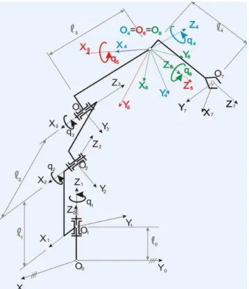
The paper determines the equations of the inverse dynamic model of the 6R articulated industrial robot, shown in fig. 1.
One of the most advantageous methods for
dynamic modelling is Newton-Euler
formulation, described in [1] and applied in [2], [3], [4], [5]. As a pre-requisite, the geometric [6] and kinematic [7] model of the 6R robot had to be determined.
An easy way to get the equations of the dynamic model is Robot_Symbolic, a MATLAB toolbox having the following components:
Robot_Definition [8], Robot_ Geometry [9],
Robot_Kinematics [10] and Robot_Dynamics
[3].
2. MASS DISTRIBUTION PARAMETERS
Beside the geometric and kinematic
parameters, the mass distribution parameters are necessary to be established in order to apply
Newton-Euler formulation [11]. Some
simplifying hypotheses are useful for setting the mass distribution parameters:
a. The mass centers Ci will be chosen into
the origins Oi of the frames Oixiyizi, i = 1÷6, such that the position vectors of
the mass centers to be null.
b. The mobile frames will be chosen such that their axes to be the main directions of inertia corresponding to the origins of these frames, the centrifugal mechanical moments of inertia being zero.
The mass distribution parameters are: the mass of element i, the position vectors of mass centers and the inertia tensors.
The masses are:
M1, M2, M3, M4, M5, M6. (1) The position vectors of mass centers, considering the first simplifying hypothesis, are:
= 0 0 0 rc11
, = 0 0 0 rc22
, = 0 0 0 rc33
, (2)
= 0 0 0 rc44
, = 0 0 0 rc55
, = 0 0 0 rc66
. (3)
The inertia tensors, considering the second simplifying hypothesis, are the following:
= 1 * z 1 * y 1 * x 1 * 1 J 0 0 0 J 0 0 0 J J , = 2 * z 2 * y 2 * x 2 * 2 J 0 0 0 J 0 0 0 J
J , (4)
= 3 * z 3 * y 3 * x 3 * 3 J 0 0 0 J 0 0 0 J J , = 4 * z 4 * y 4 * x 4 * 4 J 0 0 0 J 0 0 0 J
J , (5)
= 5 * z 5 * y 5 * x 5 * 5 J 0 0 0 J 0 0 0 J J , = 6 * z 6 * y 6 * x 6 * 6 J 0 0 0 J 0 0 0 J
J .(6)
The non-zero components of the inertia tensor, J*xi, J*yi,
i * z
J , i = 1÷6 are the axial mechanical moments of inertia with respect to the frame i, having the origin in the mass center Ci and having the same orientation as the frame attached to each of the robot’s links.
The accelerations corresponding to the mass centers are determined according to [12]. The following accelerations are established:
(
1)
c 1 1 1 1 1 c 1 1 1 1 1
c1 a r1 r1
a = +ε × +ω × ω × , (7)
[ ]
= g 0 0 a 1 1 c , (8)(
2)
c 2 2 2 2 2 c 2 2 2 2 2
c2 a r2 r2
a = +ε × +ω × ω × , (9)
[ ]
= g cq g sq 0 a 2 2 2 2 c , (10)(
3)
c 3 3 3 3 3 c 3 3 3 3 3
c3 a r3 r3
a = +ε × +ω × ω × , (11)
̄ =
+ 2
+ − + + 2 − −
+ + + + 2 − −
Due to the complexity of the equations corresponding to the mass centers 4 5 and 6 accelerations, they do not fit in this paper. Their computation formulae are the following:
(
4)
c 4 4 4 4 4 c 4 4 4 4 4
c4 a r4 r4
a = +ε × +ω × ω × , (13)
(
5)
c 5 5 5 5 5 c 5 5 5 5 5
c5 a r5 r5
a = +ε × +ω × ω × , (14)
(
6)
c 6 6 6 6 6 c 6 6 6 6 6
c6 a r6 r6
a = +ε × +ω × ω × . (15)
3. OUTWARDS ITERATIONS
According to [1], [11] and [12], the mechanical structure of the robot is parsed by outwards iterations, obtaining the system of external forces and their moments.
The external forces, applying the
computation relations, are:
[ ]
[ ]
11 c 1 1
1 M a
F = ,
=
g M
0 0 F
1 1 1
; (16)
[ ]
[ ]
2 2 c 2 22 M a
F = ,
[ ]
=
g cq M
g sq M
0 F
2 2
2 2 2 2
; (17)
[ ]
[ ]
3 3 c 3 33 M a
F = ; (18)
̄ =
+ 2
+ − + + 2 − −
+ + + + 2 − −
. (19)
The equations of external forces of the other three links are also very complex and they cannot be presented here. Their computation equations are:
[ ]
[ ]
4 4 c 4 44 M a
F = ;
[ ]
[ ]
55 c 5 5
5 M a
F = (20)
[ ]
[ ]
6 6 c 6 66 M a
F = . (21)
According to [12], the moments of the external forces are obtained as:
1 1 1 * 1 1 1 1 1 1 * 1 1
c J J
M
1 = ε +ω × ω , (22)
= 00
∗ ; (23)
2 2 2 * 2 2 2 2 2 2 * 2 2
c J J
M
2 = ε +ω × ω , (24)
=
∗ −
!∗ + ∗
!∗ + !∗ + ∗ − ∗
∗ − ∗ − ∗ +
!∗
. (25)
3 3 3 * 3 3 3 3 3 3 * 3 3
c J J
M
3 = ε +ω × ω , (26)
4 4 4 * 4 4 4 4 4 4 * 4 4
c J J
M4 = ε +ω × ω , (27)
5 5 5 * 5 5 5 5 5 5 * 5 5
c J J
M
5 = ε +ω × ω , (28)
6 6 6 * 6 6 6 6 6 6 * 6 6
c J J
M
6 = ε +ω × ω . (29)
4. INWARDS ITERATIONS
The second part of Newton-Euler formulation is dedicated to parsing the mechanical structure of the robot by inwards iterations. The connection forces and their moments are determined, as well as the generalized driving forces from the robot’s joints.
The connection forces, according to [1], [11], [12], [13], have the following computation expressions:
[ ]
66 7 l 6 7 6
l R F F
F
7
6 = ⋅ + , (30)
[ ]
55 6 l 5 6 5
l R F F
[ ]
4 4 5 l 4 5 4l R F F
F4= ⋅ 5+ , (32)
[ ]
33 4 l 3 4 3
l R F F
F
4
3 = ⋅ + , (33)
[ ]
22 3 l 2 3 2
l R F F
F2 = ⋅ 3+ , (34)
[ ]
11 2 l 1 2 1
l R F F
F
2
1 = ⋅ + , (35)
and the moments of the connection forces have the expressions:
[ ]
R M r F r[ ]
R F M ,Ml6 76 l7 c6 66 76 76 l7 c6
6 7 6 7 O 6
O = ⋅ + × + × ⋅ + (36)
[ ]
R M r F r[ ]
R F M ,M 5c
6 l 5 6 5 6 5 5 5 c 6 l 5 6 5
l 5 6 5
6 O 5
O = ⋅ + × + × ⋅ + (37)
[ ]
R M r F r[ ]
R F M ,M c4
5 l 4 5 4 5 4 4 4 c 5 l 4 5 4
lO4 = ⋅ O5 + 4× + × ⋅ 5 + 4 (38)
[ ]
R M r F r[ ]
R F M ,M 3c
4 l 3 4 3 4 3 3 3 c 4 l 3 4 3
lO3 = ⋅ O4 + 3× + × ⋅ 4+ 3 (39)
[ ]
R M r F r[ ]
R F M ,M c2
3 l 2 3 2 3 2 2 2 c 3 l 2 3 2
lO2 = ⋅ O3 + 2× + × ⋅ 3+ 2 (40)
[ ]
R M r F r[ ]
R F M ,M 1c
2 l 1 2 1 2 1 1 1 c 2 l 1 2 1
lO1 = ⋅ O2 + 1× + × ⋅ 2 + 1 (41)
giving complex equations, available at the reader’s request to the email address of the first author.
According to [1] and [13], the generalized driving forces have the following computation formulae:
[ ]
[
]
1l 1 l 1 l 1 l 1 1 T 1 l 1
m x y z z
1 O M 1 0 0 M M M k M Q = ⋅ = ⋅
= , (42)
[ ]
[
]
2l 2 l 2 l 2 l 2 2 T 2 l 2
m O2 x y z Mx
0 0 1 M M M i M Q = ⋅ = ⋅
= , (43)
[ ]
[
]
3l 3 l 3 l 3 l 3 3 T 3 l 3
m O3 x y z Mx
0 0 1 M M M i M Q = ⋅ = ⋅
= , (44)
[ ]
[
]
4l 4 l 4 l 4 l 4 4 T 4 l 4
m x y z z
4 O M 1 0 0 M M M k M Q = ⋅ = ⋅
= , (45)
[ ]
[
]
5l 5 l 5 l 5 l 5 5 T 5 l 5
m O5 x y z Mx
0 0 1 M M M i M Q = ⋅ = ⋅
= , (46)
[ ]
[
]
6l 6 l 6 l 6 l 6 6 T 6 l 6
m O6 x y z Mz
1 0 0 M M M k M Q = ⋅ = ⋅
= . (47)
In this case of articulated robot, all the generalized driving forces have the significance of moments.
5. CONCLUSION
The dynamic study of articulated robots allows choosing the proper motors for their joints, as well as the optimal arrangement of modules in a modular robotic structure, such that the energy consumption to be minimum for a given task.
The obtaining of the dynamic equations was possible using the component Robot_Dynamics
[3] from the toolbox Robot_ Symbolic [1], [8], [9], [10], [3], written in MATLAB.
6. FUTURE WORK
There are many possible ways of further development of this work. One of them is to study the errors in the 6R articulated industrial robot, by means of geometric, kinematic and dynamic operation precision [14].
Another way is to plan the motion of the robot, based on polynomial functions, having a given task in a given environment [15], [16], [17].
The latest research published in [18] - [21] opens a new approach in modeling the dynamics of the sudden motions in robotics and multibody systems, based on the acceleration energy.
7. REFERENCES
Thesis, Technical University of Cluj-Napoca, 2007.
[2] Bugnar, F., Nedezki, C.M., Trif, A.,
Dynamic Model of 5R Articulated Industrial Robot Used in Welding Processes, Acta Technica Napocensis, Series: Appplied Mathematics, Mechanics and Engineering, Vol 60, No 1, ISSN 1221-5872, Cluj-Napoca, 2016.
[3] Deteșan, O.A., The Dynamic Modelling of the Robot Mechanical Structure Using the Symbolic Computation in MATLAB, Acta Technica Napocensis, Series: Appplied Mathematics, Mechanics and Engineering, Vol 56, No 4, ISSN 1221-5872, Cluj-Napoca, 2013.
[4] Deteșan, O.A., The Dynamic Model of RTTRR Serial Robot – the Determination of the Generalized Driving Forces, Acta Technica Napocensis, Series: Appplied Mathematics, Mechanics and Engineering, Vol 59, No 1, ISSN 1221-5872, Cluj-Napoca, 2016.
[5] Deteșan, O.A., Vahnovanu, A.D., The Dynamic Model of RTTRR Serial Robot – Iterations Outwards and Inwards the Robot’s Mechanical Structure, Acta Technica Napocensis, Series: Appplied Mathematics, Mechanics and Engineering, Vol 59, No 1, ISSN 1221-5872, Cluj-Napoca, 2016. [6] Bugnar, F., Gui (Lung) R.M., Ispas, V., The
Geometric Modeling of the Articulate 6R Robot, Acta Technica Napocensis, Series: Appplied Mathematics, Mechanics and Engineering, Vol 55, No 1, ISSN 1221-5872, Cluj-Napoca, 2012.
[7] Bugnar, F., Ispas, V., Budăcan, I., The Direct Kinematic Model of the Articulate 6R Robot, Acta Technica Napocensis, Series: Appplied Mathematics, Mechanics and Engineering, Vol 56, No 1, ISSN 1221-5872, Cluj-Napoca, 2013.
[8] Deteșan, O.A., The Definition of the Robot Mechanical Structure Using the Symbolic Computation in MATLAB, Acta Technica Napocensis, Series: Appplied Mathematics and Mechanics, Vol 51, No 4, ISSN 1221-5872, Cluj-Napoca, 2008.
[9] Deteșan, O.A., Bugnar, F., Using the Symbolic Computation in MATLAB for
Determining the Geometric Model of Serial Robots, Acta Technica Napocensis, Series: Appplied Mathematics, Mechanics and Engineering, Vol 55, No 3, ISSN 1221-5872, Cluj-Napoca, 2012.
[10] Deteşan, O.A., Ispas, Vrg., The Kinematic Modelling of the Robot Mechanical Structure Using the Symbolic Computation in MATLAB, Annals of DAAAM for 2009 & Proceedings of 20th DAAAM International Symposium “Intelligent Manufacturing & Automation: Theory, Practice & Education” (ISI Proceedings), ISSN 1726-9679, Wien, 2009.
[11] Negrean, I., Duca, A., Negrean, C., Kacso, K., Mecanică avansată în robotică, U.T. Press, ISBN 978-973-662-420-9, Cluj-Napoca, 2008.
[12] Bugnar, F., Modelarea dinamică a roboţilor industriali articulaţi, Research Report III, Cluj-Napoca, 2013.
[13] Ispas, V., Manipulatoare şi roboţi industriali, Editura Didactică şi Pedagogică, ISBN 973-30-1349-8, Bucureşti, 2004.
[14] Negrean, I., Negrean, D.C., New
Formulations About Dynamic Accuracy In Robotics, A&QT-R 2004 (THETA 14), 2004 IEEE-TTTC - International Conference on Automation, Quality and Testing, Robotics, May 13 – 15, 2004, Cluj-Napoca, Romania. [15] Deteșan, O.A., The Path Planning of
Industrial Robots Using Polynomial Interpolation, with Applications to Fanuc LR-Mate 100iB, Acta Technica Napocensis, Series: Appplied Mathematics, Mechanics and Engineering, Vol 56, No 4, ISSN 1221-5872, Cluj-Napoca, 2013.
[16] Deteșan, O.A., Bugnar, F., Trif, A., Nedezki, C.M., The Path Planning of TRR Small-Sized Robot, Acta Technica Napocensis, Series: Appplied Mathematics, Mechanics and Engineering, Vol 59, No 3, ISSN 1221-5872, Cluj-Napoca, 2016. [17] Deteșan, O.A., The Path Planning of
[18] Negrean, I., New Approaches on Notions from Advanced Mechanics, Acta Technica Napocensis, Series: Appplied Mathematics, Mechanics and Engineering, Vol 61, No 2, ISSN 1221-5872, Cluj-Napoca, 2018. [19] Negrean, I., Advanced Notions and
Differential Principles of Motion in Analytical Dynamics, Journal of Engineering Sciences and Innovation, Technical Sciences Academy of Romania, Vol 1, No 1, 49-72, ISSN 2537-320X, Bucharest, 2016.
[20] Negrean I., Formulations on Input
Parameters in Advanced Dynamics,
published in ActaTechnica Napocensis, Series: Applied Mathematics, Mechanics and Engineering, Vol. 61,Issue III, 2018, ISSN 1221-5872, pp. 305-312
[21] Negrean I., Advanced Equations in Analytical Dynamics of Systems, published in ActaTechnica Napocensis, Series:
Applied Mathematics, Mechanics and
Engineering, Vol. 60,Issue IV, 2017, ISSN 1221-5872, pp. 503-514
MODELUL DINAMIC AL ROBOTULUI INDUSTRIAL ARTICULAT 6R, FOLOSIND FORMALISMUL NEWTON-EULER
Rezumat: Articolul descrie procesul de obținere a ecuațiilor dinamice ale robotului industrial articulat 6R, utilizat în procese de sudură. Lucrarea utilizează ecuațiile modelului geometric și cinematic, determinate în prealabil. Scopul acestei analize este obținerea expresiilor forțelor generalizate ale robotului, reprezentând ecuațiile modelului dinamic invers.
Florin BUGNAR, Ph.D. Eng., Technical University of Cluj-Napoca, B-dul Muncii, no. 103-105, email: [email protected], Phone: +40743111693, Cluj-Napoca, Romania.
Claudiu Mihai NEDEZKI, Ph.D. Eng., Associate Professor, Technical University of Cluj Napoca, Department of Engineering and Robotics, e-mail: [email protected], Office Phone +40264401639, Home Address: Calea Turzii street, no. 67, Home Phone +40264440639.