Sharif University of Technology
Scientia IranicaTransactions D: Computer Science & Engineering and Electrical Engineering www.scientiairanica.com
A new algorithm for the computation of the decimals of
the inverse
P. Saha
a;and D. Kumar
ba. Department of Electronics and Communication Engineering, National Institute of Technology Meghalaya, Meghalaya-793003, Shillong, India.
b. Department of Computer Science and Engineering, National Institute of Technology Meghalaya, Meghalaya-793003; Shillong, INDIA.
Received 3 November 2014; received in revised form 4 December 2015; accepted 27 February 2016
KEYWORDS Algorithm; Arithmetic; Decimal inverse; T-Spice;
Propagation delay; Ancient mathematics.
Abstract.Ancient mathematical formulae can be directly applied to the optimization of the algebraic computation. A new algorithm used to compute decimals of the inverse based on such ancient mathematics is reported in this paper. Sahayaks (auxiliary fraction) sutra has been used for the hardware implementation of the decimals of the inverse. On account of the ancient formulae, reciprocal approximation of numbers can generate \on the y" either the rst exact n decimal of inverse, n being either arbitrary large or at least 6 in almost all cases. The reported algorithm has been implemented, and functionality has been checked in T-Spice. Performance parameters, like propagation delay and dynamic switching power consumptions, are calculated through spice-spectre of 90 nm CMOS technology. The propagation delay of the resulting 4-digit reciprocal approximation algorithm was only 1:8 uS and consumed 24:7 mW power. The implementation methodology oered substantial reduction of propagation delay and dynamic switching power consumption from its counterpart (NR) based implementation.
© 2017 Sharif University of Technology. All rights reserved.
1. Introduction
Nowadays, decimal computation plays a pivotal role in human-centric areas such as nancial and internet-based applications in which exact results are expected. Thereby, hardware implementation of Applying Spe-cic Integrated Circuits (ASICs) has gained popularity during the last decade [1-5]. Generally, hardware implementation of the computer arithmetic circuits is based on binary number systems due to simplic-ity of operations from decimal number systems [6]. Moreover, lots of decimal numbers cannot be repre-sented exactly in binary format due to nite word-length eect [6], hence appropriate representation in
*. Corresponding author.
E-mail addresses: [email protected] (P. Saha); [email protected] (D. Kumar)
binary format has been impractical. Recently, decimal arithmetic has been presented for general-purposed computer [7] with the help of Binary Coded Decimal (BCD) encoding techniques.
Reciprocal approximation plays a pivotal role for several applications such as digital signal and image processing, computer graphics, scientic computing, etc. [8]. Moreover, division operation can be com-puted with the help of reciprocal approximation in the following manner: the reciprocal of divisor is computed rst, and then it is used as the multiplier in a subsequent multiplication with the dividend [9]. This method is particularly economical when dividend is varying with respect to the same divisor. Nowadays, `reciprocal approximation' methods are typically based on the Newton-Raphson method [10]. Although, due to its poor performance (high computation time), it is more infrequently used than the other two basic
arithmetic operations such as addition and multipli-cation [11].
Substantial amount of algorithms and their hard-ware implementation has been reported so far [8-12]. All of the algorithms are based on either Taylor se-ries [12] or iterative techniques (Newton-Raphson [9,10] or Gold-Schmidt [11]). These basic algorithms have been amalgamated, and extensive work has been carried out, and then reported by researchers [8-11]. The mentioned algorithms have long latencies or large area overhead due to its linear convergence rate, thereby a huge number of operations are required for computation. Moreover, the iterative methods start with an initial approximation of the reciprocal of the divisor, usually implemented through a look-up table, thereby large ROM size is required to accommodate the denominator leading to higher delay and power. Thereby, the desired precision level of the reciprocal unit is limited by the ROM size as the size of the lookup table increases with the demand of precision level.
In algorithmic and structural levels, a signicant number of algorithms and hardware implementation methodologies have been developed to reduce the propagation delay (latency), which was based on the reduction of the iteration leading to latency reduction, but the principle behind the algorithms are same. In this paper, reciprocal algorithm and its hardware architecture based on ancient mathematics has been addressed. Sahayaks (auxiliary fraction), a Sanskrit term from Vedas, is encountered to realize the recip-rocal circuitry. This paper extends the previous paper of the same authors [13] and two others, where the inversion algorithm was introduced for the rst time to discuss circuit implementation of a division unit that uses this algorithm. With the help of the ancient methodology, reciprocal algorithm has been realized by algebraic transformation of the digits to smaller ones, and the overall division has been carried out through the transformed digits; thereby, circuit complexity has been reduced substantially due to reduction in propagation delay.
To carry out the transistor level implementa-tion of decimal reciprocal unit, optimized 4221 BCD recording techniques [14,15] have been adopted in this study. The reciprocal unit is fully optimized in terms of
calculations; thereby, any conguration of input could be elaborated. Transistor-level implementation of such reciprocal circuitry has been carried out by the combi-nation of BCD arithmetic with ancient mathematics. Performance parameters, such as propagation delay and dynamic switching power consumption of the re-ported method, have been calculated by spice/spectre models through 90 nm CMOS technology and been compared with the other design like Newton-Raphson (NR) [7] based implementation. The calculated results revealed that 4-digit reciprocal units have propagation delay of only 1:8 uS with 24:7 mW dynamic switching power consumption.
2. Ancient methodology for reciprocal computation
The gifts of the ancient Indian mathematics in the eld of mathematical science are not well recognized. Ancient books oered the mathematical operations which can be carried out mentally to produce fast answers using the sutras. In this paper, sahayaks (auxiliary fraction) for implementing the reciprocal algorithm is presented.
2.1. Examples
To fully understand the algorithm, take an example of
1
a9, where a = 1; 2; ; 9. In the conversion of such
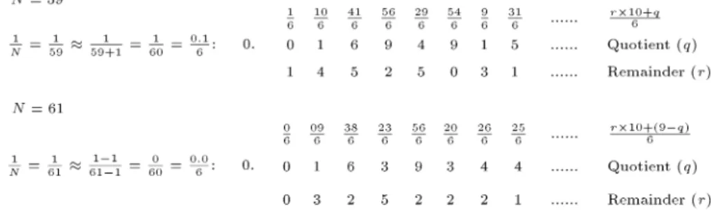
an irregular fraction into recurring decimal, ekadhika (by one more than the previous) process can be used. Assume a = 5; thus, we want to calculate the value of 1
59. Hence, ekadhika purva (one more than the
previous) is 5 + 1 = 6. The method of the division has been described in Figure 1. The description of the chart implementation procedure is described in Table 1. One more example is given in Appendix A.
2.2. Algebraic proof of sutra Let x = q0
10+100q1 +1000q2 +10000q3 + be an unknown
inverse of number N.
If N = 59, we are going to verify that 6 is the appropriate divisor in the `avalanche' of Euclidean divisions, a = bq + r, where the new dividend is obtained by concatenating the previous rest, rk, with
the previous quotient, qk, (or a function f(qk) of the
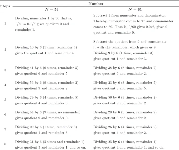
Table 1. Chart implementation procedure of the examples, shown in Figure 1.
Steps Number
N = 59 N = 61
1
Dividing numerator 1 by 60 that is, 1=60 = 0:1=6 gives quotient 0 and remainder 1.
Subtract 1 from numerator and denominator. Thereby, numerator comes to `0' and denominator comes to 60. That is, 0/60 gives 0.0/6, gives 0 quotient and remainder 0.
2 Dividing 10 by 6 (1 time, remainder 4) gives the quotient 1 and remainder 4.
Subtract the quotient from 9 and concatenate it with the remainder, which gives us 9. Dividing 9 by 6 (1 time, remainder 3) gives quotient 1 and remainder 3. 3 Dividing 41 by 6 (6 times, remainder 5)
gives quotient 6 and remainder 5.
Dividing 38 by 6 (6 times, remainder 2) gives quotient 6 and remainder 2. 4 Dividing 56 by 6 (9 times, remainder 2)
gives quotient 9 and remainder 2.
Dividing 23 by 6 (3 times, remainder 5) gives quotient 3 and remainder 5. 5 Dividing 29 by 6 (4 times, remainder 5)
gives quotient 4 and remainder 5.
Dividing 56 by 6 (9 times, remainder 2) gives quotient 9 and remainder 2. 6 Dividing 54 by 6 (9 times, no remainder)
gives quotient 9 and remainder 0.
Dividing 20 by 6 (3 times, remainder 2) gives quotient 3 and remainder 2. 7 Dividing 09 by 6 (1 time, remainder 3)
gives quotient 1 and remainder 3.
Dividing 26 by 6 (4 times, remainder 2) gives quotient 4 and remainder 2. 8 Dividing 31 by 6 (5 times and remainder 1)
gives quotient 5 and remainder 1, and so on.
Dividing 25 by 6 (4 times, remainder 1) gives quotient 4 and remainder 1, and so on.
previous quotient, in the general case): 8 > > > > > > < > > > > > > :
r0= 6q0+ r0
10r0+ q0= 6q1+ r1
10r1+ q1= 6q2+ r2
10r2+ q2= 6q3+ r3
etc. ) 8 > > > > > > < > > > > > > : r0
10 = 6q100 +r100 r0
10+100q0 = 6100q1 +100r1 r1
100+1000q1 = 61000q2 +1000r2 r2
1000+10000q2 = 610000q3 +10000r3
etc:
(1)
Considering q0 = 0, the right-hand side equations
are obtained by dividing the left-hand side equations, especially by 10, 100, 1000, . Then, adding together all these equations, except the rst one by canceling and factoring, one obtains:
r0
10+ x
10 = 6x , 59x = r0:
This equality proves that if we take r0 = 1, x is the
desired inverse of 59 with qks as its decimals as long as
all these qks are less than 10, which is the case here.
The general proof is along the same lines with: 8 > > > > > > > > < > > > > > > > > :
r0= dq0+ r0
10r0+ f(q0) = dq1+ r1
10r1+ f(q1) = dq2+ r2
10r2+ f(q2) = dq3+ r3
10r3+ f(q3) = dq4+ r4
etc:
(2)
(here also, q0= 0).
Function f(::) is to be replaced by one of the appropriate rules; for example, if fqk = 2qk, one
obtains the following by the operation having been done before (division by 10, 100, 1000, and then adding):
r0
10+ 2 x
Taking r0 = 2, one has (5d + 1)x = 1; thus, we have
obtained a recipe for getting all the decimals of the inverse of integers of the form 5d + 1. Here, qk 10.
The ancient rule for recipe implementation is given in Appendix B.
2.3. Implementation of reciprocal algorithm Pseudo-code for the implementation of the reciprocal algorithm has been given hereunder. As seen in the pseudo-code, the last digit of the denominator has been calculated through mod-10 operation. If the last digits are 2, 4, and 6, then it is multiplied by 5; if the last digit is 5, then it is multiplied by 2. If the last digit is 3, then it is multiplied by 4. If the last digit is 0, then the right-shift operation is directly performed. If the last digit is 1 or \7, 8, and 9", then the direct implementation of the algorithm is performed. The multiplication process is carried out for digit reduction from denominator. The algorithm will continue until 16 oating point number:
N //reciprocal number X = 10 //Base 10
NoD = Number of digits in Number N Num = 1 //Numerator
p = 0
Result = 0 //i.e. reciprocal of N Flag=0 ; F 1 = F 2 = 1 //ags while (F 1 AND F 2)
LSD=MoD(N,X)
while ismember(LSD, [2,3,4,5,6]) LSD = MoD(N,X)
Flag =1 switch LSD
case f2,4,6g: m = 5 case 3: m = 4 case 5: m = 2 end
Num = Num m N = N m end
switch LSD
case f7,8,9g: N = N + X LSD case 0: Flag=0
N = N + X case 1 : N = N 1
Num=Flag Num end
N = N=X p = p + 1
F 1 = (Flag == 1)
F 2 = Number of digits in N NoD end
if (NOT F 1) for d = 1 : 16
q = Num=N //integer division
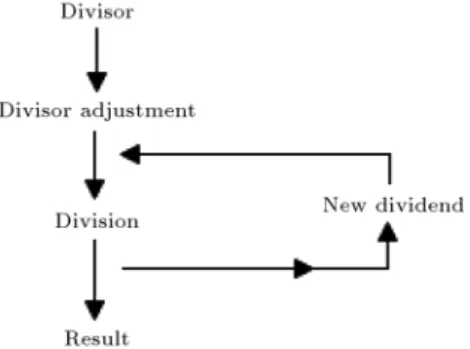
Figure 2. Block level architecture of the reciprocal architecture implementation.
r = MoD(Num; N) Result = Result X + q
q = MoD(q; X) //keep single digit if LSD==1
Num = r X 1 q else
Num = r X + q (X LSD) end
end p = d end
Result = Result X p //multiply by 10 p
3. Circuit modules
The proposed reciprocal algorithm technique, shown in Figure 2, is used to implement the hardware archi-tecture. Here, basic block diagram is included. First, the input numbers (i.e., dividend) are taken, and they are forwarded to the divisor adjustment unit. The division adjustment unit consists of comparator, adder, subtractor, and multiplier block. When dividend digits are reduced, then division adjustment unit is promoted for the division circuitry. The block level architecture is shown in Figure 2. Likewise, the reciprocal calculation algorithm is implemented.
3.1. Divisor adjustment unit
Divisor adjustment unit is shown in Figure 3, where the input is the divisor and the last digit of the divisor is propagated to the comparator. When the last digit of the divisor is 9, then ignore the last digit and increment the previous digit by one. When the last digit of the divisor is eight, then ignore the digit and send a
signal to a new dividend generation unit for the next iteration. Likewise, when the last digit is 3, then multiply the numerator and denominator by 4. When the last digit is equal to 5, then multiply the numerator and denominator by 2, then ignore the last digit of the denominator and perform the division.
3.2. Division
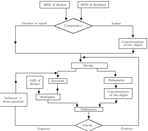
In this section, divider and hardware implementation algorithms are described to increase the speed of the operation. Where input of the algorithm is initialized as divisor (dvs) and dividend (dvd), and output is given as quotient and remainder. `n' is the number of the digits in dividend and `i' is the number of iteration. The ow chart for the algorithm is shown in Figure 4. The example of the algorithm is shown in Appendix C for this algorithm.
The divider implementation technique is shown in Figure 5. The dividend is assumed to have larger length than the divisor length for simplicity. First, the input numbers of the divisor and dividend are taken from the Most Signicant Digit (MSD) side. If the MSD of dividend is greater than MSD of divisor, then
Figure 4. High-speed division implementation of ow chart diagram.
divide the dividend MSD by divisor MSD; otherwise, the two most signicant digits taken from the dividend side are considered and divided by the divisor. After division, quotient and remainder are generated. The remainder is concatenation of the next MSD of the dividend and subtracted from the multiplication result of the quotient digit and the least signicant digit of divisor. If the result is negative, the quotient is reduced by 1 and set the new quotient digit; else it is promoted to the next stage. Likewise, the division algorithm is implemented.
3.3. BCD computation
In this paper, we consider the optimized 4221 coding technique for decimal digit representation. As we have mentioned, the use of BCD-8421 to represent decimal digits is expensive because decimal corrections in the partial product reduction binary CSA tree are required to obtain the correct decimal carry and sum. Mathematical representation for the addition technique can be represented as in the following:
Ai+ Bi+ Ci= 3
X
i=0
(ai;j+ bi;j+ ci;j)ri= 3
X
j=0
si;jrj
+ 2 X3
j=0
hi;jrj= Si+ 2Hi; (3)
where r3 r2 r1 r0 2 f(4221); (5211)g, si;j, and
hi;j are the sum and carry bits of full adders,
respec-tively. Hi; Si 2 [0; 9] are the decimal carry and sum
digits, respectively. Decimal correction is not required for this 4-bit vector expressions of Hi, Si because of
coding (4221 and 5211) techniques. Moreover, decimal multiplication by 2 is required for further usage of carry digit, Hi. The implementation procedure (algorithmic
level) for the usage of the carry bit is shown in Figure 6.
4. Results and discussions
The functionality of the proposed algorithm is ex-amined using spice-spectre simulator. Transistor-level simulation was performed through spice spectre simulator of 90 nm CMOS technology with `1' volt node voltage, operated at 250 MHz. First, all the circuit modules of full-custom cells are used, and nally the complete architecture that combines all the modules is simulated, so that the decoding performance can be considered and reected in the results. The simulations have been conducted for all possible bit combinations. The performances, shown in the result section, are the worst-case scenarios when delay and consumed power are maximized for any specic bit combinations. More examples for the calculation of the reciprocal of numbers are given in Appendix C. The reported methodology revealed that the application of
Figure 5. Hardware implementation of divider .
Figure 6. Calculation of carry digit (Hi) based on 4221 coding schemes.
the ancient mathematics for reciprocal implementation reduces the number of iterations. Thereby, hardware usage decreases; as a result, propagation delay and dynamic switching power consumptions decrease. 4.1. Error analysis
The computational error can be dened as: Er= exact value assumed valueexact value 100:
The reciprocal of the divisor, 1
N, is calculated using the
Newton-Raphson iterative method. The rst iteration uses an initial seed, herein obtained using a piecewise linear approximation based on minimax polynomials. The method converges quadratically, that is, the error
of the approximation decreases quadratically with the number of iterations. Calculation of the error in the proposed algorithm is described here:
X Y +k=
X Y
X Y
k Y
+XY
k Y
2
XY
k Y
3
+ (4) Here, the error is:
Er=Y + kX XY
= XY
(k Y
k Y
2 +
k Y
3 +
) ; (5)
=XY
k Y
( 1
k Y
1
+
k Y
2
k Y
3
+ )
; (6)
= XY Yk
1 k Y
: (7)
Percentage of error is equal to: Er(%) = EXr
Y
100 = Y +kX XY X Y
100
= XY Yk
X Y
1 k
Y
100 = Yk
1 k Y
100: (8)
Figure 7. Error analysis chart as a function of input number of digit.
Figure 8. Histogram analysis as a function of input numbers.
Computational error, Er, can be minimized if (XY(Yk)+ X
Y(Yk)2XY(Yk)3) is added to or subtracted from the
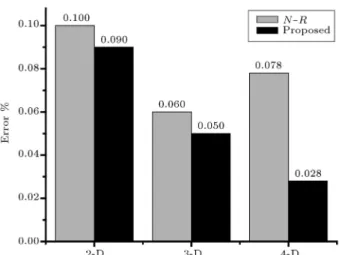
approximated result. The comparison chart based on the proposed methodology is given in Figure 7. In Figure 7, comparison of the errors and the N-R methodology are described. MATLAB programming has been implemented using IEEE single precision format, and the value has been calculated for dierent digits. The error graph shows the approximate and average errors. We have taken the algorithm (N-R) [10] from references and computed it in the same environ-ment for calculation. The number of exact decimals provided by the algorithm is shown in Figure 8. The histogram analysis, shown in Figure 8, reveals that above (approximately) 400, at least 5 decimals are exact, i.e. the error is under 10 6.
4.2. Comparison
The performance parameters, such as propagation delay and dynamic switching power consumption, are shown in Table 2 as a function of input number of digits. Input data are taken as possible digit combina-tion for experimental purposes. We have kept our main concentration on reducing the performance parameters such as propagation delay, dynamic switching power consumption, thereby energy delay product.
Proper modications for device, circuit, and
ar-Table 2. Performance parameters' comparison graph as a function of input number of digits: Propagation delay (uS) and dynamic switching power consumption (mW).
Algorithm No. of digits
Propagation delay
(uS)
Power (mW)
N-R
2-D 0.52 9.63
3-D 1.07 14.97
4-D 2.45 27.34
Proposed
2-D 0.38 7.81
3-D 0.79 12.52
4-D 1.83 24.76
chitectural levels of design hierarchy have been ana-lyzed properly for reducing propagation delay and av-erage dynamic power consumption. The values of delay and power of dierent architectures are measured. Pass transistor/Transmission Gates (TG) are used for the design of dierent modules for faster operation and better logic transformation. The basic dierence of pass-transistor logic compared to the CMOS logic style is that the source side of the logic transistor networks is connected to some input signals instead of the power lines. The advantage is that one pass-transistor net-work (either NMOS or PMOS) is sucient to perform the logic operation, which results in a smaller number of transistors and smaller input loads, demonstrated in high speed and less power consumption [16]. For each transition, the delay is computed by 50% of the input voltage swing to 50% of the output voltage swing.
The propagation delay and the power consump-tion have been measured with the assumpconsump-tion of the worst-case pattern and from the output where the delay is maximized. Individual circuit module has been simulated, and nally the complete circuit module has been carried out in a similar approach. For comparison purposes, the architectures have been taken from dierent references [9,10] and implemented using technological environment.
A comparison between dierent architectures in terms of propagation delay and dynamic switching power consumption is also shown in Table 2. Simu-lation results for 4-digit reciprocal of a number oered 25% speed compared with N-R iteration-based [10] architecture. Moreover, the improvement in terms of switching power is 9% in the same environment.
5. Conclusions
In this paper, a new algorithm for the computation of the decimals of the inverse based on ancient math-ematics is reported. By employing such an ancient methodology, decimal reciprocal has been implemented by the transformation of the digits into a smaller
one. Moreover, division has been carried out through smaller (transformed) digits. Transformation oered the reduction of circuit-level complexity, owing to the substantial reduction in propagation delay. The functionality of these circuits is checked, and the per-formance parameters, such as propagation delay and dynamic power consumptions, are calculated through spice spectre of standard 90nm CMOS technology. Simulation results for 4 digits reciprocal of a number oered 25% reduction in terms of propagation delay compared with N-R iteration-based [10] architecture, whereas the corresponding improvement in terms of switching power is equal to 9% in the same envi-ronment.
References
1. James, R.K., Shahana, T.K., Jacob, K.P. and Sasi,
S. \Decimal multiplication using compact BCD mul-tiplier", Proc. IEEE Int. Conf. Electronics Design, Penang, pp. 1-6 (2008).
2. Gorgin, S. and Jaberpur, G. \Comment on high speed
parallel decimal multiplication with redundant inter-nal encodings", ", IEEE Transactions on Computers, 64(1), pp. 293-294 (2015).
3. James, R.K., Jacob, K.P. and Sasi, S. \Performance
analysis of double digit decimal multiplier on various FPGA logic families", Proc. IEEE Int. Conf. on Programmable Logic, Sao Carlos, pp. 165-170 (2009).
4. Sutter, G., Todorovich, E., Bioul, G., Vazquez, M.
and Deschamps, J.P. \FPGA implementations of BCD multipliers", Proc. IEEE Int. Conf. on Recongurable Computing and FPGAs (ReConFig '09), Quintana Roo, pp. 36-41 (2009).
5. Zhu, M. and Jiang, Y. \An area-time ecient
archi-tecture for 16 16 decimal multiplications", Proc. of Information Technology: New Generations (ITNG), Las Vegas, pp. 210-216 (2013).
6. Veestias, M.P. and Neto, H.C. \Parallel decimal
multipliers using binary multiplier", Proc. IEEE VI Southern Programmable Logic Conf. (SPL), Ipojuca, pp. 73-78 (2010).
7. Jaberipur, G. and Kaivani, A. \Binary-coded decimal
digit multipliers", IET J. on Computer & Digital Techniques, 1(4), pp. 377-381 (2004).
8. Schulte, M.J., Stine, J.E. and Wires, K.E. \High-speed reciprocal approximations", Proc. of the Thirty-First Asilomar Conf. on Signals, Systems & Computers, Pacic Grove, pp. 1183-1187 (1997).
9. Chen, D. and Ko, S.B. \Design and implementation
of decimal reciprocal unit", Proc. Canadian Conf. on Electrical and Computer Engineering, Vancouver, pp. 1094-1097 (2007).
10. Fowler, D.L. and Smith, J.E. \An accurate, high speed
implementation of division by reciprocal approxima-tion", Proc. 9th Symp. on Computer Arithmetic, Santa Monica, pp. 60-67 (1989).
11. Pineiro, J.A. and Bruguera, J.D. \High-speed
double-precision computation of reciprocal, division, square root, and inverse square root", IEEE Trans. on Com-puters, 52(12), pp. 1377-1388 (2002).
12. Farmwald, P.M. \High bandwidth evaluation of
ele-mentary functions", Proc. Fifth IEEE Symp. Com-puter Arithmetic, Ann Arbor, pp. 139-142 (1981).
13. Saha, P., Kumar, D., Bhattacharyya, P. and
Danda-pat, A. \Reciprocal unit based on Vedic mathematics for signal processing applications", Proc. of the IEEE, Int. Symp. Electronics Design (ISED), Singapore, pp. 41-45 (2013).
14. Bhattacharya, J., Gupta, A. and Singh, A. \A high
performance binary to BCD converter for decimal multiplication", Proc. Int. Symp. on VLSI Design Au-tomation and Test (VLSI-DAT), pp. 315-318 (2010).
15. Vazquez, A., Antelo, E. and Montuschi, P. \A new
family of high-performance parallel decimal multipli-ers", Proc. IEEE Symp. on Computer Arithmetic, Montepellier, pp. 195-204 (2007).
16. Zimmermann, R. and Fichtner, W. \Low-power logic
styles: CMOS versus pass-transistor logic", IEEE Trans. on Solid State Circuits, 32(7), pp. 1070-1090 (1997).
Appendix A
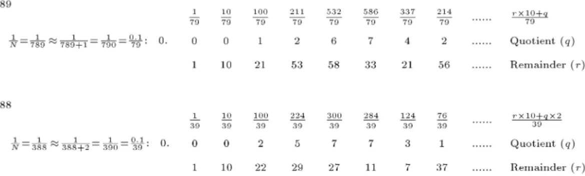
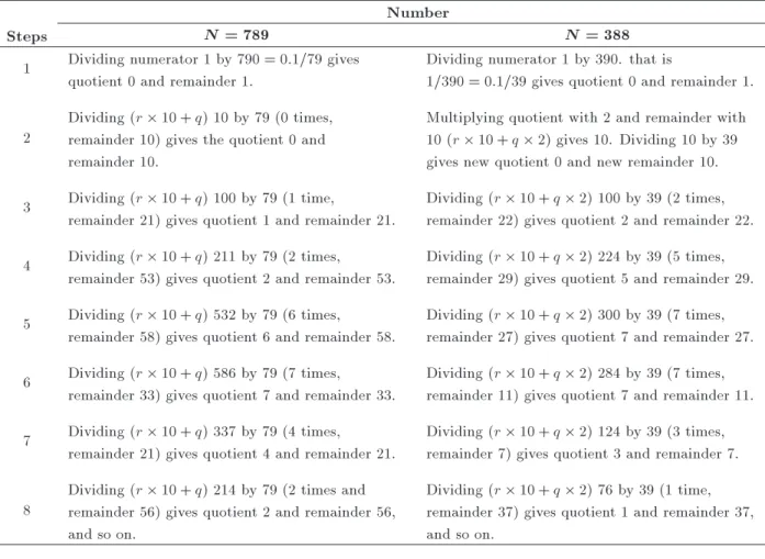
One more example is shown in Figure A.1. Chart implementation procedure is described in Table A.1.
Table A.1. Chart implementation procedure of the examples, shown in Figure A.1. Number
Steps N = 789 N = 388
1 Dividing numerator 1 by 790 = 0:1=79 gives quotient 0 and remainder 1.
Dividing numerator 1 by 390. that is
1=390 = 0:1=39 gives quotient 0 and remainder 1.
2
Dividing (r 10 + q) 10 by 79 (0 times, remainder 10) gives the quotient 0 and remainder 10.
Multiplying quotient with 2 and remainder with 10 (r 10 + q 2) gives 10. Dividing 10 by 39 gives new quotient 0 and new remainder 10. 3 Dividing (r 10 + q) 100 by 79 (1 time,
remainder 21) gives quotient 1 and remainder 21.
Dividing (r 10 + q 2) 100 by 39 (2 times, remainder 22) gives quotient 2 and remainder 22. 4 Dividing (r 10 + q) 211 by 79 (2 times,
remainder 53) gives quotient 2 and remainder 53.
Dividing (r 10 + q 2) 224 by 39 (5 times, remainder 29) gives quotient 5 and remainder 29. 5 Dividing (r 10 + q) 532 by 79 (6 times,
remainder 58) gives quotient 6 and remainder 58.
Dividing (r 10 + q 2) 300 by 39 (7 times, remainder 27) gives quotient 7 and remainder 27. 6 Dividing (r 10 + q) 586 by 79 (7 times,
remainder 33) gives quotient 7 and remainder 33.
Dividing (r 10 + q 2) 284 by 39 (7 times, remainder 11) gives quotient 7 and remainder 11. 7 Dividing (r 10 + q) 337 by 79 (4 times,
remainder 21) gives quotient 4 and remainder 21.
Dividing (r 10 + q 2) 124 by 39 (3 times, remainder 7) gives quotient 3 and remainder 7.
8
Dividing (r 10 + q) 214 by 79 (2 times and remainder 56) gives quotient 2 and remainder 56, and so on.
Dividing (r 10 + q 2) 76 by 39 (1 time, remainder 37) gives quotient 1 and remainder 37, and so on.
Appendix B
Ancient rule for recipe implementation: Let:
ri 10
D = quotientQi, remainder ri+1. then:
ri 10 = QiD + ri+1D;
where:
(Dividend = Divisor Quotient + Remainder);
) ri 10D = Qi+ri+1D ;
) ri
D = Qi10 1+ ri+1
D 10 1; i.e.:
ri
D =
1
X
i=1
Qi10 i:
Appendix C
The example of the divider algorithm is shown in Figure C.1, and chart implementation procedure is
Table C.1. Chart implementation procedure of the examples is considered in Figure C.1.
1) One digit of divisor, i.e., `8' (MSD), has been put a little down compared to the rest of divisor digits (i.e., `3'); this is going to be the actual divisor for subsequent division process. Since 1st digit of dividend (`4') is less than divisor (`8'), take two digits of dividend, i.e. `49', as temporary dividend. After division, we get `6' as 1st quotient digit and `1' as remainder at the completion of 1st stage.
2) In 2nd stage, temporary dividend (i.e., `00') is generated by concatenating the remainder of 1st stage (i.e., `1') with the next unused digit of actual divisor ( i.e. `8') and subtracting it by the product of the rest of divisor digits, `3' and quotient digit `6' of the last stage. After division, we get `0' as 2nd quotient digit and `00' as remainder at the completion of 2nd stage.
3) In 3rd stage, temporary dividend (i.e., `07') is generated like in 2nd stage, and we get `0' as 3rd quotient digit and `07' as remainder at the completion of this stage.
4) In 4th stage, temporary dividend (i.e., `73') is generated like in previous cases. But in this stage, we do not do division and stop the procedure since stopping criteria are met (i.e., the last digit of actual dividend has been used). Thus, we get `600' as quotient and temporary dividend, `73', as remainder.
Biographies
Prabir Saha was born in Kolkata, India, in February 1980. He received BTech, MTech, and PhD degrees in 2003, 2008, and 2014, respectively. Presently, he is working as an Assistant Professor in Electronics and Communication Engineering Department in National Institute of Technology Meghalaya, India. His research interest includes VLSI design, digital signal processing, and digital image processing.
Deepak Kumar was born in Muzaarpur, India, in January, 1983. He received his BE degree from VTU, Belgaum, in 2007, and ME degree from Ben-gal Engineering and Science University, Shibpur, in 2009.
Presently, he is pursuing the PhD degree at National Institute of Technology, Meghalaya, India. His research interest includes computational mathe-matics, digital signal processing, and digital image processing.