Sharif University of Technology
Scientia IranicaTransactions B: Mechanical Engineering www.scientiairanica.com
Multi-objective optimization of truss structures using
the bee algorithm
A. Moradi
a, A. Mirzakhani Nafchi
b;and A. Ghanbarzadeh
a a. Department of Mechanical Engineering, Shahid Chamran University, Ahvaz, Iran.b. Department of Mechanical Engineering, Payame Noor University, Tehran, P.O. Box 19395-3697, Iran. Received 5 August 2012; received in revised form 17 May 2014; accepted 6 December 2014
KEYWORDS Bee Algorithm (BA); Multi-objective; Optimization; Pareto; Truss design.
Abstract.This paper aims to apply a multi-objective optimization method for optimizing a truss design problem. This method is named the Multi-Objective Bee Algorithm (MOBA). In the rst problem, objective functions minimize stress in two members and minimize the volume of the truss. In each of the other three problems, the objectives to be optimized are the value of the total weight of the structure and the total displacement of nodes, considering limits on the cross section of the elements. The bee algorithm is developed based on the principle of multi-objective problems. A clustering algorithm is applied for the multi-objective bee algorithm in order to manage the size of the Pareto-optimal set. The results provide good evidence of the robustness and eectiveness of the multi-objective bee algorithm in solving the multi-objective optimal truss design.
© 2015 Sharif University of Technology. All rights reserved.
1. Introduction
Optimization methods play very important roles in practical issues, in particular, computer sciences, en-gineering and business decision making. Conventional optimization methods, such as calculus based, listing based and random search, have a high probability of being trapped in a local optimum.
Many population-based algorithms have been in-troduced and used that are less prone to becoming stuck in local optimum. In mentioning some of these algorithms, we can begin with Particle Swarm Optimization (PSO). This algorithm is developed by considering the nature of bird ocks. Another is Ant Colony Optimization (ACO), which is inspired by the foraging behavior of ants and emphasizes the question of how ants can nd the shortest path between their nest and food.
*. Corresponding author.
E-mail addresses: [email protected] (A. Moradi); [email protected] (A. Mirzakhani Nafchi); [email protected] (A. Ghanbarzadeh)
The basic version of all these algorithms is de-signed for a single objective problem. However, many real-world problems are categorized as multi-objective problems. In multi-objective optimization problems, several goals must be achieved concurrently in order to obtain an optimal solution. These objectives are usu-ally in conict with each other, are not commensurable and must be achieved simultaneously. One way to solve this kind of problem is to take one of the objectives as a main objective and the others as constraints. The disadvantage of this approach is the limiting of available choices, which makes the optimization process a complex task. Another approach is to combine all the objectives and make a single objective function.
During the last decade, multi-objective optimiza-tion has become a well-studied research area. The rst application of multi-objective optimization con-cepts in structures began in 1968, in a paper by Krokosky [1]. Stadler [2] described the scientic application of the concept of Pareto optimality to problems of natural structural shapes. He used this concept for the optimal initial shapes of uniform shal-low arches. Rao [3,4] undertook signicant work in
multi-objective structural optimization with uncertain parameters. Carmichael [5] suggested the use of the e-constraint method to the multi-objective optimum design of trusses. Another more formal treatment of this subject was given by Koski and Silvennoinen [6] who proposed a numerical method to generate the Pareto optimal set of a truss. In further research, Koski and Silvennoinen [7] proposed scalarization of the dimension of the problem using a partial weighting method. Fu and Frangopol [8] formulated a multi-objective structural optimization technique based on structural reliability theory. This approach was ex-plained by solving a hyper static truss. EI-Sayed et al. [9] used linear goal-programming techniques with successive linearization to solve nonlinear structural optimization problems. Hajela and Shin [10] presented a slight variation of the global criterion approach, used in conjunction with a branch and bound algorithm. Another variant of the global criterion approach was suggested by Saravanos and Chamis [11]. Tseng and Lu [12] applied goal programming. Grandhi et al. [13] presented a reliability-based decision criterion approach for multi-objective optimization of struc-tures with a large number of design variables and constraints. Lounis and Cohu [14] used a projected Lagrangian algorithm to transform the multi-objective optimization of prestressed concrete structures into single objective optimization problems. A book by Eschenanuer et al. [15] is a very valuable guide to some of the most relevant work in multi-objective design optimization in the last few years. Good surveys on multi-objective structural optimization may be found in [16-18]. Various algorithms for generating the Pareto set of various optimization problems, such as the (bounded) knapsack problem [19], ant-Q algo-rithms [20], fuzzy logic [21], neural networks [21,22], and genetic algorithms [23-27] have also been devel-oped.
Nowadays, a more appropriate way to deal with multiple objective problems is to use techniques that were originally designed for that purpose in this re-search area. The bee algorithm is one of these new techniques in the optimization eld.
This algorithm does not use mathematical equa-tions but is a population-based algorithm which mimics the foraging behavior of honey bees and is inspired by their swarm intelligence [28]. It is based on three main components: (1) Food source position, corresponding to a feasible solution to the given problem; (2) Amount of nectar, which indicates the quality of the solution; and (3) The bee type: employed, onlooker, and scout bee.
The bee algorithm has two balanced searches. The rst is a local search that explores a neighborhood around some determined answers, and the second is a random global search that explores the total feasible
area. All these features contribute to the novelty of the bee algorithm.
In this study, the design of truss systems is performed by the bee algorithm. The multi-objective bee algorithm is used in solving the problem. The goals in this optimization process are, in the rst case, to minimize stress and volume, and for the other three cases, to minimize the weight of the structure and the displacement.
The paper is organized as follows. Section 2 ex-plains the multi-objective optimization problems math-ematically. Section 3 explains the Pareto optimality. Section 4 briey discusses the colony of honey bees in nature. Section 5 outlines the main steps of the bee algorithm. Section 6 explains optimization problems. Section 7 presents the results obtained using the bee algorithm and other optimization procedures.
2. Multi-objective optimization
This paper describes application of the bee algorithm to objective optimization problems. The multi-objective optimization procedure yields a set of non-determined solutions, called a Pareto optimal set, each of which is a trade-o between objectives and can be selected by the user, regarding application and the project limits. The bee algorithm is a search procedure inspired by the way honey bees forage for food. The general multi-objective optimization problem is posed as follows [29]:
minimize fi(x) i = 1; 2; :::; l
subject to Cj(x) = 0 j = 1; 2; :::; m
hk(x) 0 k = 1; 2; :::; p
X = (x1; x2; :::; xn)T; (1)
where fi(x) are the objective functions, X is the
column vector of the n independent variables, cj(x)
are equality constraints, and hk(x) are inequality
constraints. Taken together fi(x), cj(x) and hk(x) are
known as the problem function. The word `minimize` means that we aim to minimize all objective functions simultaneously. If there is no conict between the objective functions, then, a solution can be found where every objective function reaches its optimum. To avoid such trivial cases, it is assumed that there is not a single solution that is optimal with respect to every objective function. This means that objective functions are at least partly conicting. They may also have dierent units.
3. Pareto optimum
We say that a point, x 2 F , is Pareto optimal if, for
x 2 I fi(x) = fi(x); (2)
or there is at least one i 2 I, such that:
fi(x) < fi(x): (3)
Simply, this denition says that xis Pareto optimal if
no feasible vector x exists, which would decrease some criteria without causing a simultaneous increase in at least one criterion. Unfortunately, the Pareto optimum almost always gives not a single solution, but rather a set of solutions called non-dominated solutions. 4. Bees in nature
A colony of honey bees can develop and extend itself over long distances in order to exploit a large number of food sources at the same time [30,31]. The foraging process starts in a colony by scout bees being sent to search for promising ower patches. Scouts y around and look for food. When they nd a source of nectar or pollen, they y back to the colony and start dancing to communicate with other bees in a particular region in the comb. Figure 1 presents the decoding of the language of the bee dance [32].
Hence, the behavior of the scout scenario is
Figure 1. Decoding the language of the bee dance.
summarized according to the following activities:
The scout leaves its colony, searching for food sources in a random way.
Once it nishes a full trip, it returns to its colony.
When a scout arrives at the colony, it goes inside the hive and announces its presence by wing vibrations. This means that it has a message to communicate.
If it has found a nearby source of nectar or pollen, it created a circular dance. The nearby bees follow it through this circular dance and smell it for the identity of the owers. They listen to the intensity of the wing vibrations to indicate the value of the food source.
If the source is near, no direction is given. Alter-natively, if the ower source is far from the colony, careful directions must be given.
The abstract convention that the scout uses is that the up position on the comb is the position of the sun. Because bees can see polarized light, they can tell the sun's position without actually watching it. The scout dances in a precise angle from the vertical direction. This equals the horizontal angle of the sun, with reference to the colony exit, with the location of the food source.
In the next step, the scout bee must tell the other bees how far away the ower source is. This will be done by waggling the abdomen from side to side. The slower the waggling, the farther away is the distance of the food ower from the colony.
Thus, the dance of the scouts shows the direction, distance, and quality of the food source. What Von Frisch notes is that the various groups of scouting bees compete with each other and, therefore, the decision is nally made in favor of the best domicile [33].
5. The bee algorithm
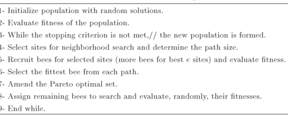
This section summarizes the main steps of the Bee Algorithm (BA). Pham et al. [34,35] proposed the bee algorithm, which is a population-based algorithm imitating the food foraging behavior of swarms of honey bees. For more detail, the reader is referred to [36-41]. Table 1 shows the pseudo code for the bee algorithm. The algorithm requires a number of parameters which should be set, namely: the number of scout bees (n), the number of sites selected for the neighborhood search (out of n visited sites) (m), the number of top-rated (elite) sites among m selected sites (e), the number of bees recruited for the best e sites (nep), the number of bees recruited for the other
(m e) selected sites (nsp), the initial size of each
patch (ngh) (a patch is a region in the search space
Table 1. Psudeo code of the bees algorithm. 1- Initialize population with random solutions.
2- Evaluate tness of the population.
3- While the stopping criterion is not met,// the new population is formed. 4- Select sites for neighborhood search and determine the path size.
5- Recruit bees for selected sites (more bees for best e sites) and evaluate tness. 6- Select the ttest bee from each path.
7- Amend the Pareto optimal set.
8- Assign remaining bees to search and evaluate, randomly, their tnesses. 9- End while.
and the stopping criterion. The algorithm starts with n scout bees randomly distributed in the search space (step 1). The tness of the sites (i.e. the performance of the candidate solutions) visited by the scout bees is evaluated in step 2. While the stopping criterion is not met, the new population is formed (step 3).
In step 4, the m non-dominated sites are desig-nated as \selected sites" and selected for a neighbor-hood search. If there are more than m non-dominated sites in the population, the rst m will be selected, because it is not possible to dierentiate between them. If there are less than m non-dominated sites, from those which have been dominated only once, the rest will be selected, and this procedure is continued until a sucient number of sites have been chosen. In step 5, a large patch size is chosen initially. For each patch, the initial size is kept unchanged as long as the recruited bees can nd better solutions in its neighborhood. If the neighborhood search does make any progress, the patch size is decreased. This strategy aims at making the local search more exploitative, searching the area around the local optimum more densely. Henceforth, this step will be called the \shrinking method" as well. In step 6, the algorithm searches around the se-lected sites. In the basic version of the bee algorithm, it assigned more bees to search in the vicinity of the best e sites and selection of the best sites was made according to the tness associated with them. In the multi-objective optimization version of the bee algorithm, as it involves more than one objective function, it is not possible to rank the solution candidates all the time. So, all the selected sites have the same number of recruited bees to search around the neighborhood. In step 7, the representative bee will be the original one, unless it is dominated by one of the recruited ones; in that case, the representative would be the new non-dominated bee. In step 8, which has been added to the basic version of the bee algorithm, in order to be capable of dealing with multi-objective optimization problems, if the ttest is a non-dominated solution, it will be added to the Pareto optimal set. In addition, if this solution dominates the other solutions in the performed Pareto optimal set, the dominated
ones will be removed from the set. In step 9, in a case where no improvement is gained using the shrinking method, it is assumed that the patch is centered on the local peak performance of the solution space. Once the neighborhood search has found a local optimum, no further progress is possible. Consequently, the exploration of the patch is terminated. Henceforth, this step is referred to as \abandon sites without new information". In step 10, the remaining bees in the population are placed randomly around the search space to scout for new potential feasible solutions. At the end of each iteration, the colony has two parts to its new population: representatives from the selected patches, and scout bees assigned to conduct random searches. These steps are repeated until a stopping criterion is met.
6. Multi-objective optimization problems To introduce our new BA-based multi-objective opti-mization approach, we will use four design problems. In the rst example, objective functions minimize stresses in each of the two members, AC and BC, and minimize volume. In each of the other three examples, two ob-jectives will be considered: minimizing the weight, and minimizing the sum of deection nodes using the cross sectional area of each element as the design variables. These objectives are conicting in nature, because, if we wish to reduce displacement, we need to increase the cross-sectional area, consequently, increasing the weight of the structure. These objectives are also non-commensurable, because, whereas weight usually has large values, maximum allowable displacement has, in general, small values.
A simple diagram of truss analysis and multi-objective optimization is described in Figure 2. 6.1. Multi-objective optimization of 2-bar
truss design
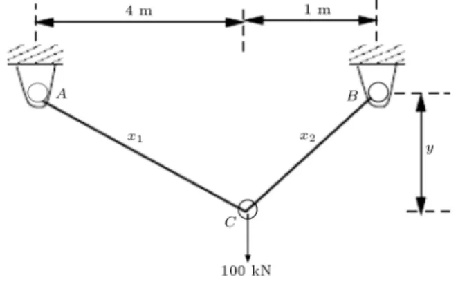
Figure 3 illustrates the two-bar truss that is to be optimized. This problem was originally studied using the "-constraint method [42]. It is comprised of two stationary pinned joints, A and B, where each one is
Figure 2. Simple diagram for a multiobjective optimization problem.
Figure 3. 2-bar truss with the objective of minimizing the stresses in AC and BC and the total structural weight.
connected to one of the two bars in the truss. The two bars are pinned where they join one another at joint C, and a 100 kN force acts directly downward at that point. The cross-sectional areas of the two bars are represented as x1 and x2; the cross-sectional
areas of trusses AC and BC, respectively. Finally, y represents the perpendicular distance from the line AB that contains the two-pinned base joints to the connection of the bars where the force acts (joint C). The problem has been modied into a two-objective
problem in order to show the non-inferior Pareto set clearly in two dimensions. The stresses in AC and BC should not exceed 100,000 kPa. Hence, in order to generate Pareto optimal solutions in a reasonable range, objective constraints are imposed. The problem formulation is shown below:
min 8 > < > :
f1(x) = x1
p
16 + y2+ x2p1 + y2
f2(x) = max (AC; BC)
(4) Subject to:
max (AC; BC) 1(105)
1 y 3
xi 0; (5)
where: AC= 20
p 16 + y2
yx1
BC= 80
p 1 + y2
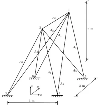
Figure 4. 9-bar space truss with the objective of minimizing weight and the sum of deection of nodes 1 and 2.
Table 2. The loading and displacement bounds for 9-bar space truss system.
Joint
number Loading (kN)
Displacement limitation
(cm)
X Y Z X Y
1 80 0 -32 0.2 0.2
2 -80 48 -32 0.2 0.2
6.2. Multi-objective optimization of 9-bar truss design
The design of the 9-bar space truss, shown in Figure 4, is considered with the objective of minimizing weight and the sum of deection of nodes 1 and 2. Location of the external load is shown in Figure 4. The loading of the truss and the upper bounds for the displacements of the restricted joints are given in Table 2. The members of the space truss are collected in 3 groups. The minimum cross-sectional area for members is chosen as 2 cm2. The modulus of elasticity is taken as
2:06 104 kN/cm2. This problem can be written
compactly as: min
8 > < > :
w(x) =P9i=1Aili
(x) =P2i=1q 2
ik+ 2iy+ iz2
: (7)
The design variables are bounded as:
A(l)i Ai A(u)i i = 1; 2; 3; (8)
Figure 5. 56-bar space truss with the objective of minimizing the total structural weight and the 1st nodal displacement.
where the limiting values are taken as: A(l)i = 2:0 cm2; A(u)
i = 10 cm2; i = 1; 2; 3: (9)
6.3. Multi-objective optimization of 56-bar truss design
This problem includes 56-bar space trusses whose members are collected in three groups, which are shown in Figure 5. Angle sections are adopted for members. Joint 1 is loaded with 4 kN in the Y -direction and 30 kN in the Z--direction, while the others are loaded with 4 kN in the Y -direction and 10 kN in the Z-direction. The vertical displacements of joints 4, 5, 6, 12, 13 and 14 are restricted to 4 cm, while the displacement of joint 8 in the Y-direction is limited to 2 cm. The loading of the truss and the upper bounds for the displacements of the restricted joints are given in Table 3. The modulus of elasticity and the minimum member cross-sectional areas are taken as 2:06 104 kN/cm2 and 2 cm2,
respectively.
The total structural weight, w(x), and the 1st nodal displacement, (x), have to be minimized simul-taneously. We write the two objective optimization
Table 3. The loading and displacement bounds for 56-bar space truss system.
Joint number
Loading (kN)
Displacement limitation
(cm)
X Y Z Y Z
1 0 4 30 -
-2 0 4 10 -
-3 0 4 10 -
-4 0 4 10 - 4
5 0 4 10 - 4
6 0 4 10 - 4
7 0 4 10 -
-8 0 4 10 2
-9 0 4 10 -
-10 0 4 10 -
-11 0 4 10 -
-12 0 4 10 - 4
13 0 4 10 - 4
14 0 4 10 - 4
15 0 4 10 -
-16 0 4 10
17 0 4 10
problems as follows: min
8 < :
w(x) =P56i=1Aili
(x) =q 2
ix+ iy2 + iz2
(10)
The design variables are bounded as:
A(l)i Ai A(u)i ; i = 1; 2; 3 (11)
where the limiting values are taken as: A(l)i = 2:0 cm2; A(u)
i = 20 cm2; i = 1; 2; 3: (12)
6.4. Multi-objective optimization of 120-bar truss design
The fourth structure is a 120-bar nonlinear space truss whose members are collected in 7 groups, as shown in Figure 6. Angle sections are adopted for members. The loading of the truss and the upper bounds for the displacements of the restricted joints are given in Table 4. The modulus of elasticity and the minimum member cross-sectional area are taken as 2:06 104 kN/cm2 and 2 cm2, respectively. The
problem formulation is shown below: min
8 > < > :
w(x) =P120i=1Aili
(x) =q 2
ix+ iy2 + iz2
(13)
The design variables are bounded as:
A(l)i Ai A(u)i ; i = 1; 2; :::; 7 (14)
where the limiting values are taken as:
Figure 6. 120-bar space truss with the objective of minimizing the total structural weight and the 1st nodal displacement.
Table 4. The loading and displacement bounds for 120-bar space truss system.
Joint
number Loading (kN)
Displacement limitation (cm)
X Y Z Z
1 0 0 60 1
2 0 0 30 1
. . . . .
. . . . .
. . . . .
14 0 0 30 1
15 0 0 10 1
. . . . .
. . . . .
. . . . .
37 0 0 10 1
A(l)i = 2:0 cm2; A(u)
i = 10 cm2; i = 1; 2; 3: (15)
7. Results and discussion
7.1. Multi-objective optimization of two-bar truss design
The empirically chosen parameters for the bee algo-rithm are given in Table 5. Figure 7 shows the
non-Table 5. Parameter of the bees algorithm. n m e nep nsp ngh imax
100 20 4 50 8 0.1 200
Figure 7. Non-dominated solutions obtained for the 2-bar truss design problem using the bees algorithm and other optimization methods.
dominated solutions obtained using the bee algorithm. Deb has investigated this problem [43] using the non-dominated sorting GA (or NSGA), and another dif-ferent predecessor, NSGA, called NASGA-II, for nd-ing multiple Pareto optimal solution. In comparison with the number of solutions found by non-dominated sorting genetic algorithms, it can be seen that the bee algorithm can nd more non-dominated solutions.
According to Table 6, the solutions are spread in the following range: [(0.00403 m3, 99642.131 kPa),
(0.07877 m3, 7661.940 kPa)], respectively, which
indi-cates the superiority of the bee algorithm compared to other optimization methods.
If minimization of stress is important, the bee algorithm nds a solution with stress as low as 7661.940 kPa, whereas the NSGA-II has found a solution with minimum stress of 8439 kPa. Also, if minimization of volume is important, NSGA-II nds the amount of 0.00407 m3 for volume, whereas the
bee algorithm nds a solution with a minimum volume of 0.00403 m3. According to results (Figure 7. and
Figure 8. Non-dominated solutions obtained for the 9-bar truss design problem using the bees algorithm and other optimization methods.
Table 6), bee algorithm solutions are better than other methods, both in terms of closeness to the optimum front and in their spread. Another detail worth mentioning is that all these solutions have been found in just one simulation run of the bee algorithm. 7.2. Multi-objective optimization of 9-bar
truss design
The empirically chosen parameters for the bee al-gorithm are given in Table 5. Figure 8 shows the non-dominated solutions obtained using the bee algo-rithm. According to Figure 8, regarding the number of solutions found by non-dominated sorting genetic algorithms, it can be seen that the bee algorithm can nd more non-dominated solutions. Also, in Fig-ure 8, the solutions are spread in the following ranges: [(2.4020 cm, 52,280 cm3), (4.5506 cm, 27,428 cm3)],
respectively, which indicates the superiority of the bee algorithm compared to other optimization methods. All these solutions have been found in just one sim-ulation run of the bee algorithm.
Kelesoglu has investigated this problem [44] using fuzzy optimization for nding the optimal solution. Table 7 summarizes the best solutions for dierent optimization methods. This table also provides a com-parison between the optimal design results reported by
Table 6. Results for 2-bar truss design obtained using the bees algorithm and other optimization methods. Objective function Methods Min (volume) (m3) Min (max stress) (KPa)
Min(max stress) BA 0.07877 7661.940
Min(volume) BA 0.00403 99642.131
Min(max stress) NSGAII [43] 0.00407 99755
Min(volume) NSGAII [43] 0.05304 8439
Min(max stress) NSGA [43] 0.042012 9474.692
Min(volume) NSGA [43] 0.021023 69996.461
Min(max stress) Palli et al. [42] 0.004445 89983
Table 7. Results for 9-bar truss design obtained using the bees algorithm and other optimization methods.
Variables Methods
Fuzzy-
Fuzzy-linear non-linear BA
[44] [44]
A1(cm2) 7.99 7.95 9.67
A2(cm2) 2.04 2.05 2.64
A3(cm2) 6.72 6.74 4.57
Min (w=) (cm3) 38,846 38,808 36,741
Min (cm) 3.33 3.37 3.30
the bee algorithm and other algorithms. According to Table 7, if min (w=) is important, the bee algorithm nds a solution with (w=) as low as 36,741 cm3, but
fuzzy-linear and fuzzy-non-linear algorithms obtained solutions of 38,846 cm3 and 38,808 cm3, respectively.
Also, for displacement, the BA found 3.30 cm, whereas, the fuzzy-linear and fuzzy-non-linear found 3.33 cm and 3.37 cm. Comparing results (Figure 8 and Table 7), one can conclude that bee algorithm solutions are better than other methods, both in terms of closeness to the optimum front and in their spread.
7.3. Multi-objective optimization of 56-bar truss design
The empirically chosen parameters for the bee al-gorithm are given in Table 5. The results for the multi-objective optimization of a 56-bar truss design are shown in Figure 9. If we attend to Figure 9, in comparison with the number of solutions found by fuzzy optimization, it can be seen that the bee algorithm can nd more non-dominated solutions, so that the solutions are spread in the following ranges: [(0.2180 cm, 39,074 cm3), (3.6427 cm, 44,088 cm3)],
respectively. This indicates the superiority of the bee algorithm compared to other optimization methods.
It should be pointed out that Kelesoglu solved this
Figure 9. Non-dominated solutions obtained for the 56-bar truss design problem using the bees algorithm and other optimization method.
Table 8. Results for 56-bar truss design obtained using the bees algorithm and other optimization methods.
Variables Methods
Fuzzy
optimization [45] BA
A1 (cm2) 12.3217 12.8042
A2 (cm2) 11.8822 1.65603
A3 (cm2) 13.0863 3.60747
Min (w=) (cm3) 326,212 164,384
Min (cm) 0.44208 0.41622
problem using the genetic algorithm to nd optimal solutions [45]. Table 8 compares the results obtained in this research with the outcome of other research. According to Table 8, if min (w=) is important, the bee algorithm nds a solution with the amount of 164,384 cm3, but fuzzy optimization calculated
326,212 cm3 for (w=). Also, for displacement, BA
found 0.41622 cm, whereas fuzzy optimization found 0.44208 cm. In comparison with the results (Figure 8 and Table 7), one can conclude that bee algorithm solutions have a very good performance, both in terms of closeness to the optimum front and in their spread. So, the bee algorithm method can nd a wide variety of solutions.
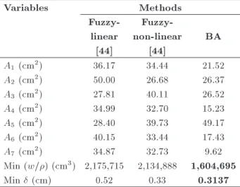
7.4. Multi-objective optimization of 120-bar truss design
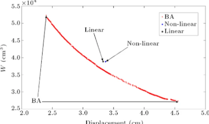
The empirically chosen parameters for the bee algo-rithm are given in Table 5. In Figure 10, we show the real Pareto-optimal solution and the result of the bee algorithm for the multi-objective optimization of the 120-bar truss design. According to Figure 10, the solu-tions are spread in the following ranges: [(0.1666 cm, 2,441,573 cm3), (0.7834 cm, 995,963 cm3)], which
shows that the bee algorithm method can nd a wide variety of solutions.
Kelesoglu has investigated this problem [44] using the Genetic Algorithm (GA) for nding optimal
solu-Figure 10. Non-dominated solutions obtained for the 120-bar truss design problem using the bees algorithm and other optimization methods.
Table 9. Results for 120-bar truss design obtained using the bees algorithm and other optimization methods.
Variables Methods
Fuzzy-
Fuzzy-linear non-linear BA
[44] [44]
A1 (cm2) 36.17 34.44 21.52
A2 (cm2) 50.00 26.68 26.37
A3 (cm2) 27.81 40.11 26.52
A4 (cm2) 34.99 32.70 15.23
A5 (cm2) 28.40 39.73 49.17
A6 (cm2) 40.15 33.44 17.43
A7 (cm2) 34.87 32.73 9.62
Min (w=) (cm3) 2,175,715 2,134,888 1,604,695
Min (cm) 0.52 0.33 0.3137
tions. Table 9 has performed a comparison between the results of the bee algorithm with the results of other optimization methods. It can be seen that the results of the proposed algorithm are better than those of the previously reported methods. If min (w=) is important, the bee algorithm nds a solu-tion with an amount of 1,604,695 cm3, but
fuzzy-linear and fuzzy-non-fuzzy-linear obtained 2,175,715 cm3and
2,134,888 cm3, respectively. Also, for displacement, BA
found 0.3137 cm, whereas the linear and fuzzy-non-linear found 0.52 and 0.33 cm, respectively. In comparison with results (Figure 10 and Table 9), one can conclude that the bee algorithm solutions have a very good performance, both in terms of closeness to the optimum front and in their spread. This indicates the superiority of the bee algorithm compared to other optimization methods.
8. Conclusion
We have presented a novel approach to solve engi-neering design problems based on a simple evolution strategy. The proposed approach has described a mod-ied version of the bee algorithm and its application to the search for multiple Pareto optimal solutions in mechanical engineering problems. We compared our results with those obtained by other algorithms that are found to perform well in the same problems. The bee algorithm found many trade-o solutions compared to the number of solutions obtained using other algo-rithms. Also, the computational cost of our approach (measured in terms of the number of evaluations of the objective function) is very low and the proposed approach is very simple and easy to implement. Thus, the bee algorithm is a computationally fast, objective optimizer tool for complex engineering multi-objective optimization problems.
References
1. Krokosky, E.M. \The ideal multifunctional construc-tural material", Int. J. of Strucconstruc-tural Division, ASCE., 94, pp. 959-982 (1968).
2. Stadler, W. \Preference optimality and application of Pareto optimality", In Marzollo/Leitmann, edi-tor, Multicriterion Decision Making, Springer Velag, Berlin, Germany (1975).
3. Rao, S.S. \Multiobjecive optimization in structural design with uncertain parameters and stochastic pro-cesses", Int. J. of AIAA, 22, pp. 1670-1678 (1984). 4. Rao, S.S. \Multi-objective optimization of fuzzy
struc-tural systems", Int. J. of Numerical Methods in Engi-neering, 24, pp. 1157-1171 (1987).
5. Carmichael, D.G. \Computation of Pareto optima in structural design", Int. J. of Numerical Methods in Engineering, 15, pp. 925-952 (1980).
6. Koski, J. and Silvennoinen, R. \Pareto optima of isostatic trusses", Int. J. of Computers Methods in Applied Mechanics and Engineering, 31, pp. 265-279 (1982).
7. Koski, J. and Silvennoinen, R. \Norm methods and partial weighting in multi-criterion optimization of structures", Int. J. of Numerical Methods in Engineer-ing, 24, pp. 1101-1121 (1987).
8. Fu, C. and Frangopol, D.M. \Reliability-based vector optimization of structural systems", Int. J. of Struc-tural Engineering, 116, pp. 2143-2161 (1990). 9. EI-Sayed, M.E., Ridgely, B.J. and Sandgren, E.
\Non-linear structural optimization using goal program-ming", Int. J. of Computers and Structures, 32, pp. 69-73 (1989).
10. Hajela, P. and Shih, C.J. \Multiobjective optimum design in mixed integer and discrete design variable problems", Int. J. of AIAA, 28, pp. 670-675 (1990). 11. Saravanos, D.A. and Chamis, C.C. \Multi-objective
shape and material optimization of composite struc-tures including damping", Int. J. of AIAA, 30, pp. 805-813 (1992).
12. Tseng, C.H. and Tung-wu, L. \Minimax multi-objective optimization in structural design", Int. J. of Numerical Methods in Engineering, 30, pp. 1213-1228 (1990).
13. Grandhi, V., Bharatram, G. and Venkayya, B. \Multi-objective optimization of large-scale structures", Int. J. of AIAA, 31, pp. 1329-1337 (1993).
14. Lounis, Z. and Chon, M.Z. \Multiobjective optimiza-tion of prestressed concrete structures", Int. J. of Structural Engineering, 119, pp. 794-808 (1993). 15. Eschenauer, H., Koski, J. and Syczka, A., Eds.
\Multicriteria Design Optimization", Procedures and Applications., 1 ed., Springer, Verla, (1990).
16. Stadler, W. \Multicriteria optimization in mechanics (a survey)", Applied Mechanics Review., 37, pp. 277-286 (1984).
17. Duckstein, L. \Multiobjective optimization in struc-tural design: The model choice problem", Arizona Univ. Tucson, Defense Technical Information Center (1981)
18. Coello, C. \An empirical study of evolutionary tech-niques for multiobjective optimization in engineering design", PhD Thesis, Department of Computer Sci-ence, Tulane University, New Orleans, LA (April, 1996).
19. Klamroth, K. and Wiecek, M. \Dynamic programming approaches to the multiple criteria knapsack problem", Int. J. of Naval Research Logistics, 47, pp. 57-76 (2000).
20. Mariano, C.E. and Morales, E. \A multiple objective ant-Q algorithm for the design of water distribution irrigation networks", Technical report HC-9904, Insti-tuto Mexicano de Tecnologa del Agua, (1999). 21. Rao, S.S., Sundararaju, K., Prakash, B.G. and
Bal-akrishna, C. \Multi-objective fuzzy optimization tech-niques for engineering design", Int. J. of Comput Struct, 42, pp. 37-44 (1992).
22. Balicki, J., Kitowski, Z. and Stateczny, A. \Extended Hopeld models of neural networks for combinatorial multi-objective optimization problems", In: The IEEE International Joint Conference on Neural Networks. IEEE World Congress on Computational Intelligence, pp. 1646-51 (1998).
23. Deb, K., Multi-Objective Optimization Using Evolu-tionary Algorithms, 1 Ed., John Wiley and Sons, New York (2001).
24. Zitzler, E., Deb, K., Thiele, L., Coello, C.A. and Corne, D. Eds., Evolutionary Multi-Criterion Opti-mization, Springer, Berlin (2001).
25. Coello, C.A., Van Veldhuizen, D.A. and Lamont, G.B. Evolutionary Algorithms for Solving Multi-Objective Problems, Kluwer Academic Publishers, New York (2002).
26. Osyczka, A., Evolutionary Algorithms for Single and Multicriteria Design Optimization, Germany: Physica Verlag (2002).
27. Nemhauser, L. and Ullmann, Z. \Discrete dynamic programming and capital allocation", Int. J. of Man-agement Science, 15, pp. 494-505 (1969).
28. Pham, D.T., Ghanbarzadeh, A., Koc, E., Otri, S., Rahim, S. and Zaidi, M. \The bees algorithm", Tech-nical Note, Cardi University, UK (2005).
29. Coello, C.A. \Multi-objective engineering design op-timization using genetic algorithms", PhD Thesis, Department of Computer Science, Tulane University (1996).
30. Osyczka, A. \Multicriteria optimization for engineer-ing design", In J.S. Gero, editor, Design Optimization, Academic Press, pp. 193-227 (1985).
31. Von Frisch, K. \Bees: their vision", Chemical Senses
and Language, Cornell University Press, Ithaca (1976). 32. Seeley, T.D., The Wisdom of the Hive: The Social Physiology of Honey Bee Colonies, Harvard University Press, Cambridge (1996).
33. Von Frisch, K. \Decoding the language of the bee", Science, 185, pp. 663-668 (1974).
34. Pham, D.T., Ghanbarzadeh, A., Koc, E., Otri, S., Rahim, S. and Zaidi, M. \The bees algorithm", Cardi University Technical Report - MEC 0501, Cardi Manufacturing Engineering Centre (2005).
35. Pham, D.T., Ghanbarzadeh, A., Koc, E., Otri, S., Rahim, S. and Zaidi, M. \The bees algorithm, a novel tool for complex optimisation problems", Proceedings of the 2nd Int Virtual Conf on Intelligent Production Machines and Systems, Oxford: Elsevier, pp. 454-459 (2006).
36. Pham, D.T., Ghanbarzadeh, A., Koc, E., Otri, S., Rahim, S. and Zaidi, M. \Technical note: Bees al-gorithm", Technical Report No MEC 0501, Manufac-turing Engineering Centre, Cardi University: Cardi (2005).
37. Pham, D.T., Ghanbarzadeh, A., Koc, E. and Otri, S. \Application of the bees algorithm to the training of radial basis function networks for control chart pattern recognition", Proceedings of the 5th CIRP International Seminar on Intelligent Computation in Manufacturing Engineering (CIRP ICME '06), Ischia, Italy, pp. 711-716 (2006).
38. Mirzakhani Nafchi, A., Moradi, A., Ghanbarzadeh, A., Rezazadeh, A. and Soodmand, E. \Solving engineering optimization problems using the bees algorithm", Pro-ceedings of the 2011 IEEE Colloquium on Humanities Science and Engineering, Penang, Malaysia, pp. 162-166 (2011).
39. Moradi, A., Mirzakhani Nafchi, G.A., Hanbarzadeh, A. and Soodmand, E. \Optimization of linear and nonlinear full vehicle model for improving ride comfort vs. road holding with the bees algorithm", Proceedings of the 2011 IEEE Colloquium on Humanities Science and Engineering, Penang, Malaysia, pp. 17-22 (2011). 40. Ahangarpoura, A., Moradi, A., Mirzakhani Nafchi, A., Ghanbarzadeh, A. and Farbod, M. \Optimization of continual production of CNTs by CVD method by using the bees algorithm and neural network", Proceedings of the 4th International Conference on Nanostructures (ICNS4), Kish Island, I.R. Iran (2012). 41. Mirzakhani Nafchi, A., Moradi, A., Ghanbarzadeh, A., Yaghoubi, S. and Moradi, M. \An improved bees algorithm for solving optimization mechanical prob-lems", Proceedings of the 20th Annual International Iranian Mechanical Engineering Conference, Shiraz Iran (2012).
42. Palli, N., Azram, S., McCluskey, P. and Sundararajan, R. \An interactive multistage inequality constraint method for multiple objectives decision making", Int. J. of Mechanical Design, 120, pp. 678-686 (1999).
43. Deb, K., Pratap, A. and Moitra, S. \Mechanical com-ponent design for multiple objectives using elitist non-dominated sorting GA", Proceedings of the Parallel Problem Solving from Nature VI Conference, Paris, France, pp. 859-868 (2000).
44. Kelesoglu, O. and Ulker, M. \Fuzzy optimization of geometrical nonlinear space truss design", Int. J. of Eng. Env. Sci., 29, pp. 321-329 (2005).
45. Kelesoglu, O. and Ulker, M. \Fuzzy multiobjective op-timization of truss-structures using genetic algorithm", Int. J. of Advances in Engineering Software, 38, pp. 717-721 (2007).
Biographies
Abbas Moradi was born in 1985 in Izeh, Iran. He received his BS degree in Mechanical Engineering from the Department of Engineering, Islamic Azad University, Ahwaz, Iran, in 2008, and his MS degree from Chamran University of Ahwaz, Iran, in 2011. He has published several research papers in refereed
international journals and conferences. He works at the National Iranian Oil Company (NIOC).
Amin Mirzakhani Nafchi was born in 1985 in Shahrekord, Iran. He received his BS and MS degrees in Mechanical Engineering from the Department of En-gineering at Chamran University of Ahwaz, in 2008 and 2011, respectively, and is currently an instructure in the Department of Mechanical Engineering at Payame Noor University, Tehran, Iran. He has published sev-eral research papers in refereed international journals and conferences. His research interests mainly focus on structural optimization, neural networks, and damage detection by ultrasonic waves.
Afshin Ghanbarzadeh received his BS and MS degrees from Chamran University, Ahwaz, Iran, and his PhD degree from Cardi University, UK. He is currently Associate Professor in the Department of Me-chanical Engineering at Chamran University, Ahwaz, Iran.