© 2009-2012 Microchip Technology Inc. DS61154C-page 34-1
Controller Area
Network
(CAN)
34
HIGHLIGHT
This section of the manual contains the following topics:
34.1 Introduction... 34-2 34.2 CAN Message Formats ... 34-4 34.3 CAN Registers... 34-9 34.4 Enabling and Disabling the CAN Module ... 34-47 34.5 CAN Module Operating Modes... 34-47 34.6 CAN Message Handling ... 34-49 34.7 Transmitting a CAN Message... 34-56 34.8 CAN Message Filtering... 34-68 34.9 Receiving a CAN Message... 34-75 34.10 Bit Timing... 34-83 34.11 CAN Error Management ... 34-87 34.12 CAN Interrupts ... 34-90 34.13 CAN Received Message Time Stamping... 34-94 34.14 Power-Saving Modes ... 34-95 34.15 Related Application Notes ... 34-96 34.16 Revision History... 34-97
DS61154C-page 34-2 © 2009-2012 Microchip Technology Inc.
34.1
INTRODUCTION
The PIC32 Controller Area Network (CAN) module implements the CAN Specification 2.0B, which is used primarily in industrial and automotive applications. This asynchronous serial data communication protocol provides reliable communication in an electrically noisy environment. The PIC32 device family integrates up to two CAN modules. Figure 34-1 illustrates a typical CAN bus topology.
Figure 34-1: Typical CAN Bus Network
The CAN module supports the following key features: • Standards Compliance:
- Full CAN Specification 2.0B compliance - Programmable bit rate up to 1 Mbps • Message Reception and Transmission:
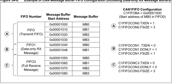
- 32 message FIFOs
- Each FIFO can have up to 32 messages for a total of 1024 messages - FIFO can be a transmit message FIFO or a receive message FIFO - User-defined priority levels for message FIFOs used for transmission - 32 acceptance filters for message filtering
- Four acceptance filter mask registers for message filtering - Automatic response to Remote Transmit Request (RTR) - DeviceNet™addressing support
Please consult the note at the beginning of the “Controller Area Network (CAN)”
chapter in the current device data sheet to check whether this document supports the device you are using.
Device data sheets and family reference manual sections are available for download from the Microchip Worldwide Web site at: http://www.microchip.com
CAN bus
CAN1
PIC® with Integrated
ECAN CAN
Transceiver
dsPIC33F with Integrated
ECAN™
dsPIC30F with Integrated
CAN
TransceiverCAN TransceiverCAN TransceiverCAN CAN2
CAN Transceiver PIC32
© 2009-2012 Microchip Technology Inc. DS61154C-page 34-3
Controller Area
Network (CAN)
34
- Loopback, Listen All Messages and Listen-Only modes for self-test, system diagnostics and bus monitoring
- Low-power operating modes
- CAN module is a bus master on the PIC32 system bus
- Does not require Direct Memory Access (DMA) channels for operation - Dedicated time stamp timer
- Data-only Message Reception mode
Figure 34-2 illustrates the general structure of the CAN module.
Figure 34-2: PIC32 CAN Module Block Diagram
The CAN module consists of a protocol engine, message acceptance filters and Message Assembly Buffers (MABs). The protocol engine transmits and receives messages to and from the CAN bus (as per CAN Specification 2.0B). Received messages are assembled in the receive message assembly buffer. The received message is then filtered by the message acceptance filters. The transmit message assembly buffer holds the message to be transmitted as it is processed by the protocol engine.
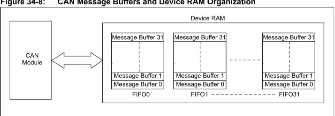
The CAN message buffers reside in device RAM. There are no CAN message buffers in the CAN module. Therefore, all messages are stored in device RAM. The CAN module is a bus master on the PIC32 system bus, and will read and write data to device RAM as required. The CAN module does not use DMA for its operation and fetches messages from the device RAM without DMA or CPU intervention.
Message Buffer 31
Message Buffer 1 Message Buffer 0 Message Buffer 31
Message Buffer 1 Message Buffer 0 Message Buffer 31
Message Buffer 1 Message Buffer 0
FIFO0 FIFO1 FIFO31
Device RAM
Up
to
32
Me
ssag
e B
u
ffer
s
CAN Message FIFO (up to 32 FIFOs)
Message Buffer Size 2 or 4 Words System Bus
CPU CAN Module
32 Filters 4 Masks CxTX
DS61154C-page 34-4 © 2009-2012 Microchip Technology Inc.
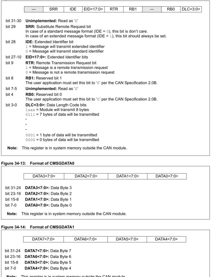
contents of the data frame as illustrated in Figure 34-3.
Each frame begins with a Start of Frame (SOF) bit field and terminates with an End of Frame (EOF) bit field. The SOF is followed by the Arbitration and Control fields, which identify the message type, format, length and priority. This information allows each node on the CAN bus to respond appropriately to the message. The Data field conveys the message content and is of variable length, ranging from 0 bytes to 8 bytes. Error protection is provided by the Cyclic Redundancy Check (CRC) and Acknowledgement (ACK) fields.
Figure 34-3: CAN Bus Message Frame
The CAN bus protocol supports four frame types:
• Data Frame – carries data from transmitter to the receivers
• Remote Frame – transmitted by a node on the bus, to request transmission of a data
frame with the same identifier from another node
• Error Frame – transmitted by any node when it detects an error
• Overload Frame – provides an extra delay between successive Data or remote frames
• Interframe Space – provides a separation between successive frames
The CAN Specification 2.0B defines two additional data formats:
• Standard Data Frame –intended for standard messages that use 11 identifier bits
• Extended Data Frame – intended for extended messages that use 29 identifier bits
There are three CAN Specification versions: • 2.0A – considers 29-bit identifier as error
• 2.0BPassive – ignores 29-bit identifier messages
• 2.0B Active – handles both 11-bit and 29-bit identifiers
The PIC32 CAN module is compliant with the CAN Specification 2.0B, while providing enhanced message filtering capabilities.
Note: For detailed information on the CAN protocol, refer to the Bosch CAN Bus
Specification 2.0B, which is available for download at:
http://www.semiconductors.bosch.de S
O F
E O F
© 2009-2012 Microchip Technology Inc. DS61154C-page 34-5
Controller Area
Network (CAN)
34
The standard data frame message begins with an SOF bit followed by a 12-bit Arbitration field as illustrated in Figure 34-4. The Arbitration field contains an 11-bit identifier and RTR bit. The identifier defines the type of information contained in the message, and is used by each receiving node to determine if the message is of interest to it. The RTR bit distinguishes a data frame from a remote frame. For a standard data frame, the RTR bit is clear.
Following the Arbitration field is a 6-bit Control field, which provides more information about the contents of the message. The first bit in the Control field is an Identifier Extension (IDE) bit, which distinguishes the message as either a standard or extended data frame. A standard data frame is indicated by a dominant state (logic level ‘0’) during transmission of the IDE bit. The second bit in the Control field is a reserved (RB0) bit, which is in the dominant state (logic level ‘0’). The last four bits in the Control field represent the Data Length Code (DLC), which specifies the number of data bytes present in the message.
The Data field follows the Control field. This field carries the message data – the actual payload of the data frame. This field is of variable length, ranging from 0 bytes to eight bytes. The number of bytes is user-selectable.
The Data field is followed by the CRC field, which is a 15-bit CRC sequence with one delimiter bit. The Acknowledgement (ACK) field is sent as a recessive bit (logic level ‘1’), and is overwritten as a dominant bit by any receiver that has received the data correctly. The message is acknowledged by the receiver regardless of the result of the acceptance filter comparison. The last field is the EOF field, which consists of seven recessive bits that indicate the end of message.
Figure 34-4: Format of the Standard Data Frame
SID10 SID1
S O F
IDENTIFIER 11 Bits
R T R
I D E RB0
DLC 4 Bits
DATA 8 Bytes
CRC 16 Bits
ACK 2 Bits
EOF 7 Bits
IFS 3 Bits
SID0
9/19/2006 - 9/26/2006
11-bit Identifier Interframe Space
9/19/2006 - 9/26/2006 9/19/2006 - 9/26/2006Data 9/19/2006 - 9/26/2006
9/19/2006 - 9/26/20069 - 9/26/2006
Frame Interframe Space
9/19/2006 - 9/26/2006
IDE is Dominant (Logical ‘0’) RTR is Dominant (Logical ‘0’) RB0 is Dominant (Logical ‘0’)
/19/
Arbitration
End-of-DS61154C-page 34-6 © 2009-2012 Microchip Technology Inc.
bits in two fields separated by a Substitute Remote Request (SRR) bit and an IDE bit. The SRR bit determines if the message is a remote frame. SRR = 1 for extended data frames. The IDE bit indicates the data frame type. For the extended data frame, IDE = 1.
The extended data frame Control field consists of seven bits. The first bit is the RTR. For the extended data frame, RTR = 0. The next two bits, RB1 and RB0, are reserved bits that are in the dominant state (logic level ‘0’). The last four bits in the Control field are the DLC, which specifies the number of data bytes present in the message.
The remaining fields in an extended data frame are identical to a standard data frame.
Figure 34-5: Format of the Extended Data Frame
SID10 SID1 S
O F
IDENTIFIER 11 Bits
S R R
I D E
R T R
DLC 4 BITS
CRC 16 BITS
ACK 2 BITS
EOF 7 BITS
IFS 3 BITS
SID0 Field
29-bit Identifier
9/19/2006 - 9/26/2006
Control 9/19/2006 - 9/26/2006CRC
9/19/2006 - 9/26/2006
IDENTIFIER 18 BITS
EID17 EID1 EID0 R B 1
R B 0
IDE is Recessive (Logical ‘1’) SRR is Recessive (Logical ‘1’) RTR is Dominant (Logical ‘0’) RB0 is Dominant (Logical ‘0’) RB1 is Dominant (Logical ‘0’)
9/19/2006 - 9/26/2006
ACK End of Frame
9/19/2006 - 9/26/2006 9/19/2006 - 9/26/2006
Data
DATA 8 Bytes Arbitration
© 2009-2012 Microchip Technology Inc. DS61154C-page 34-7
Controller Area
Network (CAN)
34
A node expecting to receive data from another node can initiate transmission of the respective data by the source node, by sending a remote frame. A remote frame can be in standard format (Figure 34-6) or the extended format (Figure 34-7).
A Remote frame is similar to a data frame, with the following exceptions: • The RTR bit is recessive (RTR = 1)
• There is no Data field (DLC = 0)
Figure 34-6: Format of the Standard Remote Frame
Figure 34-7: Format of the Extended Remote Frame
SID10 SID1 S O F IDENTIFIER 11 Bits R T R I D E DLC 4 Bits CRC 16 Bits ACK 2 Bits EOF 7 Bits IFS 3 Bits SID0 11-bit Identifier RB0
IDE is Dominant (Logical ‘0’) RTR is Recessive (Logical ‘1’) RB0 is Dominant (Logical ‘0’)
Arbitration Field Control Field CRC Field ACK Field End of Frame
SID10 SID0 S O F IDENTIFIER 11 Bits S R R I D E R T R DLC 4 Bits CRC 16 Bits ACK 2 Bits EOF 7 Bits IFS 3 Bits SID1 Arbitration Field 29-bit Identifier
Control Field CRC Field
IDENTIFIER 18 Bits
EID17 EID1 EID0 R B 1 R B 0
IDE is Recessive (Logical ‘1’) SRR is Recessive (Logical ‘1’) RTR is Recessive (Logical ‘1’) RB0 is Dominant (Logical ‘0’) RB1 is Dominant (Logical ‘0’) ACK Field
End of Frame
DS61154C-page 34-8 © 2009-2012 Microchip Technology Inc.
bits and allows the bus nodes to restart communication cleanly after an error has occurred. There are two types of error flag fields, depending on the error status of the node that detects the error:
• Error Active Flag – contains six consecutive dominant bits, which forces all other nodes
on the network to generate Error Echo Fags, thereby resulting in a series of 6 to 12 dominant bits on the bus
• Error Passive Flag – contains six consecutive recessive bits, with the result that unless
the bus error is detected by the transmitting node, the transmission of an Error Passive Flag will not affect the communication of any other node on the network
34.2.5
Overload Frame
An Overload Frame can be generated by a node either when a dominant bit is detected during Interframe Space or when a node is not ready to receive the next message (for example, if it is still reading the previous received message). An Overload Frame has the same format as an Error Frame with an Active Error Flag, but can only be generated during Interframe Space. It consists of an Overload Fag field with six dominant bits followed by an Overload Delimiter field with eight recessive bits. A node can generate a maximum of two sequential overload frames to delay the start of the next message.
34.2.6
Interframe Space
Interframe Space separates successive frames being transmitted on the CAN bus. It consists of at least three recessive bits, referred to as intermission. The Interframe Space allows nodes time to internally process the previously received message before the start of the next frame. If the transmitting node is in the Error Passive state, an additional eight recessive bits will be inserted in the Interframe Space before any other message is transmitted by the node. This period is called a Suspend Transmit field and allows time for other transmitting nodes to take control of the bus.
© 2009-2012 Microchip Technology Inc. DS61154C-page 34-9
Controller Area
Network (CAN)
34
34.3
CAN REGISTERS
The CAN module registers can be classified by their function into the following groups: • Module and CAN bit rate Configuration registers
• Interrupt and Status registers
• Mask and Filter Configuration registers • FIFO Control registers
34.3.1
Module and CAN Bit Rate Configuration Registers
• CiCON: CAN Module Control Register
This register is used to set up the CAN module operational mode and DeviceNetaddressing.
• CiCFG: CAN Baud Rate Configuration Register
This register contains control bits to set the period of each time quantum, using the baud rate prescaler, and specifies Synchronization Jump Width (SJW) in terms of time quanta. It is also used to program the number of time quanta in each CAN bit segment, including the propagation and phase segments 1 and 2.
34.3.2
Interrupt and Status Registers
• CiINT: CAN Interrupt Register
This register allows various CAN module interrupt sources to be enabled and disabled. It also contains interrupt status flags.
• CiVEC: CAN Interrupt Code Register
This register provides status bits which provide information on CAN module interrupt source and message filter hits. These values can be used to implement a jump table for handling different cases.
• CiTREC: CAN Transmit/Receive Error Count Register
This register provides information on Transmit and Receive Error Counter values. It also has bits which indicate various warning states.
• CiFSTAT: CAN FIFO Status Register
This register contains interrupt status flag for all the FIFOs.
• CiRXOVF: CAN Receive FIFO Overflow Status Register
This register contains overflow interrupt status flag for all the FIFOs.
• CiTMR: CAN TImer Register
This register contains CAN Message Timestamp timer and a Prescaler.
34.3.3
Mask and Filter Configuration Registers
• CiRXMn: CAN Acceptance Filter Mask n Register (n = 0, 1, 2 or 3)
These registers allow the configuration of the filter masks. A total of four masks are available.
• CiFLTCON0: CAN Filter Control Register 0throughCiFLTCON7: CAN Filter Control Register 7
These registers allow the association of FIFO and Masks with a filter. A Filter can be associated with any one mask. It also contains a filter enable/disable bit.
• CiRXFn: CAN Acceptance Filter n Register 7 (n = 0 through 31)
These registers specify the filter to be applied to the received message. A total of 32 filters are available.
DS61154C-page 34-10 © 2009-2012 Microchip Technology Inc.
physical address.
• CiFIFOCONn: CAN FIFO Control Register (n = 0 through 31)
These registers allow the control and configuration of CAN Message FIFOs.
• CiFIFOINTn: CAN FIFO Interrupt Register (n = 0 through 31)
These registers allow the individual FIFO interrupt sources to be enabled or disabled. They also contain interrupt status bits.
• CiFIFOUAn: CAN FIFO User Address Register (n = 0 through 31)
These registers provide the address of the memory location in the CAN message FIFO from where the next message can be read or where the next message should be written to.
• CiFIFOCIn: CAN Module Message Index Register (n = 0 through 31)
These registers provide the message buffer index (in the message FIFO) of the next message that the CAN module will transmit or where the next received message will be saved.
Table 34-1 provides a summary of all CAN-related registers. Corresponding registers appear after the summary, followed by a detailed description of each register. All unimplemented registers and/or bits within a register read as zeros.
© 2009-2012 Microchip Technology Inc. DS61154C-page 34-11
Controller Area
Network (CAN)
34
Table 34-1: CAN Controller Register Summary
Name RangeBit 31/2315/7Bit 30/22/14/6Bit 29/21/13/5Bit 28/20/12/4Bit 27/19/11/3Bit 26/18/10/2Bit 25/17/9/1Bit 24/16/8/0Bit
CiCON(1) 31:24 — — — — ABAT REQOP<2:0>
23:16 OPMOD<2:0> CANCAP — — — —
15:8 ON — SIDLE — CANBUSY — — —
7:0 — — — DNCNT<4:0>
CiCFG(1) 31:24 — — — — — — — —
23:16 — WAKFIL — — — SEG2PH<2:0>
15:8 SEG2PHTS SAM SEG1PH<2:0> PRSEG<2:0> 7:0 SJW<1:0> BRP<5:0>
CiINT(1) 31:24 IVRIE WAKIE CERRIE SERRIE RBOVIE — — —
23:16 — — — — MODIE CTMRIE RBIE TBIE
15:8 IVRIF WAKIF CERRIF SERRIF RBOVIF — — —
7:0 — — — — MODIF CTMRIF RBIF TBIF
CiVEC(1) 31:24 — — — — — — — —
23:16 — — — — — — — —
15:8 — — — FILHIT<4:0>
7:0 — ICODE<6:0>
CiTREC(1) 31:24 — — — — — — — —
23:16 — — TXBO TXBP RXBP TXWARN RXWARN EWARN
15:8 TERRCNT<7:0>
7:0 RERRCNT<7:0>
CiFSTAT(1) 31:24 FIFOIP31 FIFOIP30 FIFOIP29 FIFOIP28 FIFOIP27 FIFOIP26 FIFOIP25 FIFOIP24
23:16 FIFOIP23 FIFOIP22 FIFOIP21 FIFOIP20 FIFOIP19 FIFOIP18 FIFOIP17 FIFOIP16 15:8 FIFOIP15 FIFOIP14 FIFOIP13 FIFOIP12 FIFOIP11 FIFOIP10 FIFOIP9 FIFOIP8 7:0 FIFOIP7 FIFOIP6 FIFOIP5 FIFOIP4 FIFOIP3 FIFOIP2 FIFOIP1 FIFOIP0 CiRXOVF(1) 31:24 RXOVF31 RXOVF30 RXOVF29 RXOVF28 RXOVF27 RXOVF26 RXOVF25 RXOVF24
23:16 RXOVF23 RXOVF22 RXOVF21 RXOVF20 RXOVF19 RXOVF18 RXOVF17 RXOVF16 15:8 RXOVF15 RXOVF14 RXOVF13 RXOVF12 RXOVF11 RXOVF10 RXOVF9 RXOVF8
7:0 RXOVF7 RXOVF6 RXOVF5 RXOVF4 RXOVF3 RXOVF2 RXOVF1 RXOVF0
CiTMR(1) 31:24 CANTS<15:8>
23:16 CANTS<7:0>
15:8 CANTSPRE<15:8>
7:0 CANTSPRE<7:0>
CiRXM0(1) 31:24 SID<10:3>
23:16 SID<2:0> -— MIDE — EID<17:16>
15:8 EID<15:8>
7:0 EID<7:0>
CiRXM1(1) 31:24 SID<10:3>
23:16 SID<2:0> -— MIDE — EID<17:16>
15:8 EID<15:8>
7:0 EID<7:0>
CiRXM2(1) 31:24 SID<10:3>
23:16 SID<2:0> -— MIDE — EID<17:16>
15:8 EID<15:8>
7:0 EID<7:0>
Legend: ‘—’ = unimplemented; read as ‘0’.
Note 1: This register has an associated Clear, Set, and Invert register at an offset of 0x4, 0x8, or 0xC bytes, respectively. These registers have the same name with CLR, SET, or INV appended to the end of the register name (For example, CiCONCLR). Writing a ‘1’ to any bit position in these registers will clear, set, or invert valid bits in the associated register. Reads from these registers should be ignored.
DS61154C-page 34-12 © 2009-2012 Microchip Technology Inc. 23:16 SID<2:0> -— MIDE — EID<17:16>
15:8 EID<15:8>
7:0 EID<7:0>
CiFLTCON0(1) 31:24 FLTEN3 MSEL3<1:0> FSEL3<4:0> 23:16 FLTEN2 MSEL2<1:0> FSEL2<4:0> 15:8 FLTEN1 MSEL1<1:0> FSEL1<4:0> 7:0 FLTEN0 MSEL0<1:0> FSEL0<4:0> CiFLTCON1(1) 31:24 FLTEN7 MSEL7<1:0> FSEL7<4:0> 23:16 FLTEN6 MSEL6<1:0> FSEL6<4:0> 15:8 FLTEN5 MSEL5<1:0> FSEL5<4:0> 7:0 FLTEN4 MSEL4<1:0> FSEL4<4:0> CiFLTCON2(1) 31:24 FLTEN11 MSEL11<1:0> FSEL11<4:0> 23:16 FLTEN10 MSEL10<1:0> FSEL10<4:0> 15:8 FLTEN9 MSEL9<1:0> FSEL9<4:0>
7:0 FLTEN8 MSEL8<1:0> FSEL8<4:0> CiFLTCON3(1) 31:24 FLTEN15 MSEL15<1:0> FSEL15<4:0>
23:16 FLTEN14 MSEL14<1:0> FSEL14<4:0> 15:8 FLTEN13 MSEL13<1:0> FSEL13<4:0> 7:0 FLTEN12 MSEL12<1:0> FSEL12<4:0> CiFLTCON4(1) 31:24 FLTEN19 MSEL19<1:0> FSEL19<4:0> 23:16 FLTEN18 MSEL18<1:0> FSEL18<4:0> 15:8 FLTEN17 MSEL17<1:0> FSEL17<4:0> 7:0 FLTEN16 MSEL16<1:0> FSEL16<4:0: CiFLTCON5(1) 31:24 FLTEN23 MSEL23<1:0> FSEL23<4:0>
23:16 FLTEN22 MSEL22<1:0> FSEL22<4:0> 15:8 FLTEN21 MSEL21<1:0> FSEL21<4:0> 7:0 FLTEN20 MSEL20<1:0> FSEL20<4:0> CiFLTCON6(1) 31:24 FLTEN27 MSEL27<1:0> FSEL27<4:0> 23:16 FLTEN26 MSEL26<1:0> FSEL26<4:0> 15:8 FLTEN25 MSEL25<1:0> FSEL25<4:0> 7:0 FLTEN24 MSEL24<1:0> FSEL24<4:0> CiFLTCON7(1) 31:24 FLTEN31 MSEL31<1:0> FSEL31<4:0> 23:16 FLTEN30 MSEL30<1:0> FSEL30<4:0> 15:8 FLTEN29 MSEL29<1:0> FSEL29<4:0> 7:0 FLTEN28 MSEL28<1:0> FSEL28<4:0> CiRXFn(1)
(n = 0 through 31) 31:2423:16 SID<2:0> -—SID<10:3>EXID — EID<17:16>
15:8 EID<15:8>
7:0 EID<7:0>
CiFIFOBA(1) 31:24 CiFIFOBA<31:24>
23:16 CiFIFOBA<23:16>
15:8 CiFIFOBA<15:8>
7:0 CiFIFOBA<7:0>
CiFIFOCONn(1)
(n = 0 through 31) 31:2423:16 —— —— —— — — FSIZE<4:0>— — —
15:8 — FRESET UINC DONLY — — — —
7:0 TXEN TXABAT TXLARB TXERR TXREQ RTREN TXPR<1:0>
Legend: ‘—’ = unimplemented; read as ‘0’.
Note 1: This register has an associated Clear, Set, and Invert register at an offset of 0x4, 0x8, or 0xC bytes, respectively. These registers have the same name with CLR, SET, or INV appended to the end of the register name (For example, CiCONCLR). Writing a ‘1’ to any bit position in these registers will clear, set, or invert valid bits in the associated register. Reads from these registers should be ignored.
© 2009-2012 Microchip Technology Inc. DS61154C-page 34-13
Controller Area
Network (CAN)
34
CiFIFOINTn(1)
(n = 0 through 31) 31:2423:16 —— —— —— —— RXOVFLIE— TXNFULLIERXFULLIE RXHALFIETXHALFIE RXNEMPTYIETXEMPTYIE
15:8 — — — — — TXNFULLIF TXHALFIF TXEMPTYIF
7:0 — — — — RXOVFLIF RXFULLIF RXHALFIF RXNEMPTYIF CiFIFOUAn(1)
(n = 0 through 31) 31:2423:16 CiFIFOUA<31:24>CiFIFOUA<23:16>
15:8 CiFIFOUA<15:8>
7:0 CiFIFOUA<7:0>
CiFIFOCIn(1)
(n = 0 through 31) 31:2423:16 —— —— —— —— —— —— —— ——
15:8 — — — — — — — —
7:0 — — — CiFIFOCI<4:0>
Name RangeBit 31/2315/7Bit 30/22/14/6Bit 29/21/13/5Bit 28/20/12/4Bit 27/19/11/3Bit 26/18/10/2Bit 25/17/9/1Bit 24/16/8/0Bit
Legend: ‘—’ = unimplemented; read as ‘0’.
Note 1: This register has an associated Clear, Set, and Invert register at an offset of 0x4, 0x8, or 0xC bytes, respectively. These registers have the same name with CLR, SET, or INV appended to the end of the register name (For example, CiCONCLR). Writing a ‘1’ to any bit position in these registers will clear, set, or invert valid bits in the associated register. Reads from these registers should be ignored.
DS61154C-page 34-14 © 2009-2012 Microchip Technology Inc.
31:24 U-0 U-0 U-0 U-0 S/HC-0 R/W-1 R/W-0 R/W-0 — — — — ABAT REQOP<2:0>
23:16 R-1 R-0 R-0 R/W-0 U-0 U-0 U-0 U-0 OPMOD<2:0> CANCAP — — — —
15:8 R/W-0 U-0 R/W-0 U-0 R-0 U-0 U-0 U-0
ON(1) — SIDLE — CANBUSY — — —
7:0 U-0 U-0 U-0 R/W-0 R/W-0 R/W-0 R/W-0 R/W-0
— — — DNCNT<4:0>
Legend:
R = Readable bit W = Writable bit U = Unimplemented bit, read as ‘0’
-n = Value at POR ‘1’ = Bit is set ‘0’ = Bit is cleared x = Bit is unknown
bit 31-28 Unimplemented: Read as ‘0’
bit 27 ABAT: Abort All Pending Transmissions bit
1 = Signal all transmit buffers to abort transmission
0 = Module will clear this bit when all transmissions aborted bit 26-24 REQOP<2:0>: Request Operation Mode bits
111 = Set Listen All Messages mode
110 = Reserved; do not use
101 = Reserved; do not use
100 = Set Configuration mode
011 = Set Listen-Only mode
010 = Set Loopback mode
001 = Set Disable mode
000 = Set Normal Operation mode bit 23-21 OPMOD<2:0>: Operation Mode Status bits
111 = Module is in Listen All Messages mode
110 = Reserved
101 = Reserved
100 = Module is in Configuration mode
011 = Module is in Listen-Only mode
010 = Module is in Loopback mode
001 = Module is in Disable mode
000 = Module is in Normal Operation mode
bit 20 CANCAP: CAN Message Receive Time Stamp Timer Capture Enable bit
1 = CANTMR value is stored on valid message reception and is stored with the message
0 = Disable CAN message receive time stamp timer capture and stop CANTMR to conserve power bit 19-16 Unimplemented: Read as ‘0’
bit 15 ON: CAN On bit(1)
1 = CAN module is enabled
0 = CAN module is disabled bit 14 Unimplemented: Read as ‘0’
Note 1: If the user application clears this bit, it may take a number of cycles before the CAN module completes the
current transaction and responds to this request. The user application should poll the CANBUSY bit to verify that the request has been honored.
© 2009-2012 Microchip Technology Inc. DS61154C-page 34-15
Controller Area
Network (CAN)
34
bit 13 SIDLE: CAN Stop in Idle bit
1 = CAN Stops operation when system enters Idle mode
0 = CAN continues operation when system enters Idle mode bit 12 Unimplemented: Read as ‘0’
bit 11 CANBUSY: CAN Module is Busy bit
1 = The CAN module is active
0 = The CAN module is completely disabled bit 10-5 Unimplemented: Read as ‘0’
bit 4-0 DNCNT<4:0>: Device Net Filter Bit Number bits
11111 = Invalid Selection (compare up to 18-bits of data with EID)
•
• •
10011 = Invalid Selection (compare up to 18-bits of data with EID)
10010 = Compare up to data byte 2 bit 6 with EID17 (CiRXFn<17>) •
• •
00001 = Compare up to data byte 0 bit 7 with EID0 (CiRXFn<0>)
00000 = Do not compare data bytes
Note 1: If the user application clears this bit, it may take a number of cycles before the CAN module completes the
current transaction and responds to this request. The user application should poll the CANBUSY bit to verify that the request has been honored.
DS61154C-page 34-16 © 2009-2012 Microchip Technology Inc.
31:24 U-0 U-0 U-0 U-0 U-0 U-0 U-0 U-0
— — — — — — — —
23:16 U-0 R/W-0 U-0 U-0 U-0 R/W-0 R/W-0 R/W-0 — WAKFIL — — — SEG2PH<2:0>(1,4) 15:8 R/W-0 R/W-0 R/W-0 R/W-0 R/W-0 R/W-0 R/W-0 R/W-0
SEG2PHTS(1) SAM(2) SEG1PH<2:0> PRSEG<2:0>
7:0 R/W-0 R/W-0 R/W-0 R/W-0 R/W-0 R/W-0 R/W-0 R/W-0
SJW<1:0>(3) BRP<5:0>
Legend:
R = Readable bit W = Writable bit U = Unimplemented bit, read as ‘0’
-n = Value at POR ‘1’ = Bit is set ‘0’ = Bit is cleared x = Bit is unknown
bit 31-23 Unimplemented: Read as ‘0’
bit 22 WAKFIL: CAN Bus Line Filter Enable bit
1 = Use CAN bus line filter for wake-up
0 = CAN bus line filter is not used for wake-up bit 21-19 Unimplemented: Read as ‘0’
bit 18-16 SEG2PH<2:0>: Phase Buffer Segment 2 bits(1,5)
111 = Length is 8 x TQ
• • •
000 = Length is 1 x TQ
bit 15 SEG2PHTS: Phase Segment 2 Time Select bit(1)
1 = Freely programmable
0 = Maximum of SEG1PH or Information Processing Time, whichever is greater bit 14 SAM: Sample of the CAN Bus Line bit(2)
1 = Bus line is sampled three times at the sample point
0 = Bus line is sampled once at the sample point bit 13-11 SEG1PH<2:0>: Phase Buffer Segment 1 bits(4)
111 = Length is 8 x TQ
• • •
000 = Length is 1 x TQ
Note 1: SEG2PH ≤ SEG1PH. If SEG2PHTS is clear, SEG2PH will be set automatically.
2: 3 Time bit sampling is not allowed for BRP < 2.
3: SJW ≤ SEG2PH.
4: The Time Quanta per bit must be greater than 7 (that is, TQBIT > 7).
Note: This register can only be modified when the CAN module is in Configuration mode (OPMOD<2:0>
© 2009-2012 Microchip Technology Inc. DS61154C-page 34-17
Controller Area
Network (CAN)
34
bit 10-8 PRSEG<2:0>: Propagation Time Segment bits(4)
111 = Length is 8 x TQ
• • •
000 = Length is 1 x TQ
bit 7-6 SJW<1:0>: Synchronization Jump Width bits(3)
11 = Length is 4 x TQ
10 = Length is 3 x TQ
01 = Length is 2 x TQ
00 = Length is 1 x TQ
bit 5-0 BRP<5:0>: Baud Rate Prescaler bits
111111 = TQ = (2 x 64)/FSYS
111110 = TQ = (2 x 63)/FSYS
• • •
000001 = TQ = (2 x 2)/FSYS
000000 = TQ = (2 x 1)/FSYS
Note 1: SEG2PH ≤ SEG1PH. If SEG2PHTS is clear, SEG2PH will be set automatically.
2: 3 Time bit sampling is not allowed for BRP < 2.
3: SJW ≤ SEG2PH.
4: The Time Quanta per bit must be greater than 7 (that is, TQBIT > 7).
Note: This register can only be modified when the CAN module is in Configuration mode (OPMOD<2:0>
DS61154C-page 34-18 © 2009-2012 Microchip Technology Inc.
31:24 R/W-0 R/W-0 R/W-0 R/W-0 R/W-0 U-0 U-0 U-0 IVRIE WAKIE CERRIE SERRIE RBOVIE — — — 23:16 U-0 U-0 U-0 U-0 R/W-0 R/W-0 R/W-0 R/W-0
— — — — MODIE CTMRIE RBIE TBIE
15:8 R/W-0 R/W-0 R/W-0 R/W-0 R/W-0 U-0 U-0 U-0
IVRIF WAKIF CERRIF SERRIF(1) RBOVIF — — —
7:0 U-0 U-0 U-0 U-0 R/W-0 R/W-0 R/W-0 R/W-0
— — — — MODIF CTMRIF RBIF TBIF
Legend:
R = Readable bit W = Writable bit U = Unimplemented bit, read as ‘0’
-n = Value at POR ‘1’ = Bit is set ‘0’ = Bit is cleared x = Bit is unknown
bit 31 IVRIE: Invalid Message Received Interrupt Enable bit
1 = Interrupt request enabled
0 = Interrupt request not enabled
bit 30 WAKIE: CAN Bus Activity Wake-up Interrupt Enable bit
1 = Interrupt request enabled
0 = Interrupt request not enabled
bit 29 CERRIE: CAN Bus Error Interrupt Enable bit
1 = Interrupt request enabled
0 = Interrupt request not enabled
bit 28 SERRIE: System Error Interrupt Enable bit
1 = Interrupt request enabled
0 = Interrupt request not enabled
bit 27 RBOVIE: Receive Buffer Overflow Interrupt Enable bit
1 = Interrupt request enabled
0 = Interrupt request not enabled bit 26-20 Unimplemented: Read as ‘0’
bit 19 MODIE: Mode Change Interrupt Enable bit
1 = Interrupt request enabled
0 = Interrupt request not enabled
bit 18 CTMRIE: CAN Timestamp Timer Interrupt Enable bit
1 = Interrupt request enabled
0 = Interrupt request not enabled bit 17 RBIE: Receive Buffer Interrupt Enable bit
1 = Interrupt request enabled
0 = Interrupt request not enabled
bit 16 TBIE: Transmit Buffer Interrupt Enable bit
1 = Interrupt request enabled
0 = Interrupt request not enabled
bit 15 IVRIF: Invalid Message Received Interrupt Flag bit
1 = An invalid messages interrupt has occurred
0 = An invalid message interrupt has not occurred bit 14 WAKIF: CAN Bus Activity Wake-up Interrupt Flag bit
1 = A bus wake-up activity interrupt has occurred
0 = A bus wake-up activity interrupt has not occurred
Note 1: This bit can only be cleared by turning the CAN module OFF and ON by clearing or setting the ON bit
© 2009-2012 Microchip Technology Inc. DS61154C-page 34-19
Controller Area
Network (CAN)
34
bit 13 CERRIF: CAN Bus Error Interrupt Flag bit
1 = A CAN bus error has occurred
0 = A CAN bus error has not occurred bit 12 SERRIF: System Error Interrupt Flag bit
1 = A system error occurred (typically an illegal address was presented to the system bus)
0 = A system error has not occurred
bit 11 RBOVIF: Receive Buffer Overflow Interrupt Flag bit
1 = A receive buffer overflow has occurred
0 = A receive buffer overflow has not occurred bit 10-4 Unimplemented: Read as ‘0’
bit 3 MODIF: CAN Mode Change Interrupt Flag bit
1 = A CAN module mode change has occurred (OPMOD<2:0> has changed to reflect REQOP)
0 = A CAN module mode change has not occurred bit 2 CTMRIF: CAN Timer Overflow Interrupt Flag bit
1 = A CAN timer (CANTMR) overflow has occurred
0 = A CAN timer (CANTMR) overflow has not occurred bit 1 RBIF: Receive Buffer Interrupt Flag bit
1 = A receive buffer interrupt is pending
0 = A receive buffer interrupt is not pending bit 0 TBIF: Transmit Buffer Interrupt Flag bit
1 = A transmit buffer interrupt is pending
0 = A transmit buffer interrupt is not pending
Note 1: This bit can only be cleared by turning the CAN module OFF and ON by clearing or setting the ON bit
DS61154C-page 34-20 © 2009-2012 Microchip Technology Inc.
31:24 U-0 U-0 U-0 U-0 U-0 U-0 U-0 U-0
— — — — — — — —
23:16 U-0 U-0 U-0 U-0 U-0 U-0 U-0 U-0
— — — — — — — —
15:8 U-0 U-0 U-0 R-0 R-0 R-0 R-0 R-0
— — — FILHIT<4:0>
7:0 U-0 R-1 R-0 R-0 R-0 R-0 R-0 R-0 — ICODE<6:0>(1)
Legend:
R = Readable bit W = Writable bit U = Unimplemented bit, read as ‘0’
-n = Value at POR ‘1’ = Bit is set ‘0’ = Bit is cleared x = Bit is unknown
bit 31-13 Unimplemented: Read as ‘0’ bit 12-8 FILHIT<4:0>: Filter Hit Number bit
11111 = Filter 31
11110 = Filter 30
• •
•
00001 = Filter 1
00000 = Filter 0
bit 7 Unimplemented: Read as ‘0’
bit 6-0 ICODE<6:0>: Interrupt Flag Code bits(1)
1111111 = Reserved
• • •
1001000 = Reserved
1001000 = Invalid message received (IVRIF)
1000111 = CAN module mode change (MODIF)
1000110 = CAN timestamp timer (CTMRIF)
1000101 = Bus bandwidth error (SERRIF)
1000100 = Address error interrupt (SERRIF)
1000011 = Receive FIFO overflow interrupt (RBOVIF)
1000010 = Wake-up interrupt (WAKIF)
1000001 = Error Interrupt (CERRIF)
1000000 = No interrupt
0111111 = Reserved
• • •
0100000 = Reserved
0011111 = FIFO31 Interrupt (CiFSTAT<31> set)
0011110 = FIFO30 Interrupt (CiFSTAT<30> set)
• • •
0000001 = FIFO1 Interrupt (CiFSTAT<1> set)
0000000 = FIFO0 Interrupt (CiFSTAT<0> set)
© 2009-2012 Microchip Technology Inc. DS61154C-page 34-21
Controller Area
Network (CAN)
34
Register 34-5: CiTREC: CAN Transmit/Receive Error Count Register
Bit Range Bit 31/23/15/7 Bit 30/22/14/6 Bit 29/21/13/5 Bit 28/20/12/4 Bit 27/19/11/3 Bit 26/18/10/2 Bit 25/17/9/1 Bit 24/16/8/0
31:24 U-0 U-0 U-0 U-0 U-0 U-0 U-0 U-0
— — — — — — — —
23:16 U-0 U-0 R-0 R-0 R-0 R-0 R-0 R-0 — — TXBO TXBP RXBP TXWARN RXWARN EWARN 15:8 R-0 R-0 R-0 R-0 R-0 R-0 R-0 R-0
TERRCNT<7:0>
7:0 R-0 R-0 R-0 R-0 R-0 R-0 R-0 R-0 RERRCNT<7:0>
Legend:
R = Readable bit W = Writable bit U = Unimplemented bit, read as ‘0’
-n = Value at POR ‘1’ = Bit is set ‘0’ = Bit is cleared x = Bit is unknown
bit 31-22 Unimplemented: Read as ‘0’
bit 21 TXBO: Transmitter in Error State Bus OFF (TERRCNT ≥ 256) bit 20 TXBP: Transmitter in Error State Bus Passive (TERRCNT ≥ 128) bit 19 RXBP: Receiver in Error State Bus Passive (RERRCNT ≥ 128) bit 18 TXWARN: Transmitter in Error State Warning (128 > TERRCNT ≥ 96) bit 17 RXWARN: Receiver in Error State Warning (128 > RERRCNT ≥ 96) bit 16 EWARN: Transmitter or Receiver is in Error State Warning
bit 15-8 TERRCNT<7:0>: Transmit Error Counter bit 7-0 RERRCNT<7:0>: Receive Error Counter
Register 34-6: CiFSTAT: CAN FIFO Status Register
Bit Range Bit 31/23/15/7 Bit 30/22/14/6 Bit 29/21/13/5 Bit 28/20/12/4 Bit 27/19/11/3 Bit 26/18/10/2 Bit 25/17/9/1 Bit 24/16/8/0
31:24 R-0 R-0 R-0 R-0 R-0 R-0 R-0 R-0 FIFOIP31 FIFOIP30 FIFOIP29 FIFOIP28 FIFOIP27 FIFOIP26 FIFOIP25 FIFOIP24 23:16 R-0 R-0 R-0 R-0 R-0 R-0 R-0 R-0
FIFOIP23 FIFOIP22 FIFOIP21 FIFOIP20 FIFOIP19 FIFOIP18 FIFOIP17 FIFOIP16 15:8 R-0 R-0 R-0 R-0 R-0 R-0 R-0 R-0
FIFOIP15 FIFOIP14 FIFOIP13 FIFOIP12 FIFOIP11 FIFOIP10 FIFOIP9 FIFOIP8
7:0 R-0 R-0 R-0 R-0 R-0 R-0 R-0 R-0
FIFOIP7 FIFOIP6 FIFOIP5 FIFOIP4 FIFOIP3 FIFOIP2 FIFOIP1 FIFOIP0
Legend:
R = Readable bit W = Writable bit U = Unimplemented bit, read as ‘0’
-n = Value at POR ‘1’ = Bit is set ‘0’ = Bit is cleared x = Bit is unknown
bit 31-0 FIFOIP<31:0>: FIFOn Interrupt Pending bits
1 = One or more enabled FIFO interrupts are pending
DS61154C-page 34-22 © 2009-2012 Microchip Technology Inc.
31:24 R-0 R-0 R-0 R-0 R-0 R-0 R-0 R-0 RXOVF31 RXOVF30 RXOVF29 RXOVF28 RXOVF27 RXOVF26 RXOVF25 RXOVF24 23:16 R-0 R-0 R-0 R-0 R-0 R-0 R-0 R-0
RXOVF23 RXOVF22 RXOVF21 RXOVF20 RXOVF19 RXOVF18 RXOVF17 RXOVF16 15:8 R-0 R-0 R-0 R-0 R-0 R-0 R-0 R-0
RXOVF15 RXOVF14 RXOVF13 RXOVF12 RXOVF11 RXOVF10 RXOVF9 RXOVF8 7:0 R-0 R-0 R-0 R-0 R-0 R-0 R-0 R-0
RXOVF7 RXOVF6 RXOVF5 RXOVF4 RXOVF3 RXOVF2 RXOVF1 RXOVF0
Legend:
R = Readable bit W = Writable bit U = Unimplemented bit, read as ‘0’
-n = Value at POR ‘1’ = Bit is set ‘0’ = Bit is cleared x = Bit is unknown
bit 31-0 RXOVF<31:0>: FIFOn Receive Overflow Interrupt Pending bit
1 = FIFO has overflowed
0 = FIFO has not overflowed
Register 34-8: CiTMR: CAN TImer Register
Bit Range
Bit 31/23/15/7
Bit 30/22/14/6
Bit 29/21/13/5
Bit 28/20/12/4
Bit 27/19/11/3
Bit 26/18/10/2
Bit 25/17/9/1
Bit 24/16/8/0
31:24 R/W-0 R/W-0 R/W-0 R/W-0 R/W-0 R/W-0 R/W-0 R/W-0 CANTS<15:8>
23:16 R/W-0 R/W-0 R/W-0 R/W-0 R/W-0 R/W-0 R/W-0 R/W-0 CANTS<7:0>
15:8 R/W-0 R/W-0 R/W-0 R/W-0 R/W-0 R/W-0 R/W-0 R/W-0 CANTSPRE<15:8>
7:0 R/W-0 R/W-0 R/W-0 R/W-0 R/W-0 R/W-0 R/W-0 R/W-0 CANTSPRE<7:0>
Legend:
R = Readable bit W = Writable bit U = Unimplemented bit, read as ‘0’
-n = Value at POR ‘1’ = Bit is set ‘0’ = Bit is cleared x = Bit is unknown
bit 31-0 CANTS<15:0>: CAN Time Stamp Timer bits
This is a free-running timer that increments every CANTSPRE system clocks when the CANCAP bit (CiCON<20>) is set.
bit 15-0 CANTSPRE<15:0>: CAN Time Stamp Timer Prescaler bits
65535 = CAN time stamp timer (CANTS) increments every 65,535 system clocks •
• •
0 = CAN time stamp timer (CANTS) increments every system clock
Note 1: CiTMR will be frozen when CANCAP = 0.
© 2009-2012 Microchip Technology Inc. DS61154C-page 34-23
Controller Area
Network (CAN)
34
Register 34-9: CiRXMn: CAN Acceptance Filter Mask n Register (n = 0, 1, 2 or 3)
Bit Range
Bit 31/23/15/7
Bit 30/22/14/6
Bit 29/21/13/5
Bit 28/20/12/4
Bit 27/19/11/3
Bit 26/18/10/2
Bit 25/17/9/1
Bit 24/16/8/0
31:24 R/W-0 R/W-0 R/W-0 R/W-0 R/W-0 R/W-0 R/W-0 R/W-0 SID<10:3>
23:16 R/W-0 R/W-0 R/W-0 U-0 R/W-0 U-0 R/W-0 R/W-0 SID<2:0> — MIDE — EID<17:16> 15:8 R/W-0 R/W-0 R/W-0 R/W-0 R/W-0 R/W-0 R/W-0 R/W-0
EID<15:8>
7:0 R/W-0 R/W-0 R/W-0 R/W-0 R/W-0 R/W-0 R/W-0 R/W-0 EID<7:0>
Legend:
R = Readable bit W = Writable bit U = Unimplemented bit, read as ‘0’
-n = Value at POR ‘1’ = Bit is set ‘0’ = Bit is cleared x = Bit is unknown
bit 31-21 SID<10:0>: Standard Identifier bits
1 = Include bit, SIDx, in filter comparison
0 = Bit SIDx is ‘don’t care’ in filter operation bit 20 Unimplemented: Read as ‘0’
bit 19 MIDE: Identifier Receive Mode bit
1 = Match only message types (standard/extended address) that correspond to the EXID bit in filter
0 = Match either standard or extended address message if filters match (that is, if (Filter SID) = (Message SID) or if (FILTER SID/EID) = (Message SID/EID))
bit 18 Unimplemented: Read as ‘0’ bit 17-0 EID<17:0>: Extended Identifier bits
1 = Include bit, EIDx, in filter comparison
0 = Bit EIDx is ‘don’t care’ in filter operation
Note: This register can only be modified when the CAN module is in Configuration mode (OPMOD<2:0>
DS61154C-page 34-24 © 2009-2012 Microchip Technology Inc.
31:24 R/W-0 R/W-0 R/W-0 R/W-0 R/W-0 R/W-0 R/W-0 R/W-0 FLTEN3 MSEL3<1:0> FSEL3<4:0>
23:16 R/W-0 R/W-0 R/W-0 R/W-0 R/W-0 R/W-0 R/W-0 R/W-0 FLTEN2 MSEL2<1:0> FSEL2<4:0>
15:8 R/W-0 R/W-0 R/W-0 R/W-0 R/W-0 R/W-0 R/W-0 R/W-0 FLTEN1 MSEL1<1:0> FSEL1<4:0>
7:0 R/W-0 R/W-0 R/W-0 R/W-0 R/W-0 R/W-0 R/W-0 R/W-0 FLTEN0 MSEL0<1:0> FSEL0<4:0>
Legend:
R = Readable bit W = Writable bit U = Unimplemented bit, read as ‘0’
-n = Value at POR ‘1’ = Bit is set ‘0’ = Bit is cleared x = Bit is unknown
bit 31 FLTEN3: Filter 3 Enable bit
1 = Filter is enabled
0 = Filter is disabled
bit 30-29 MSEL3<1:0>: Filter 3 Mask Select bits
11 = Acceptance Mask 3 selected
10 = Acceptance Mask 2 selected
01 = Acceptance Mask 1 selected
00 = Acceptance Mask 0 selected bit 28-24 FSEL3<4:0>: FIFO Selection bits
11111 = Message matching filter is stored in FIFO buffer 31
11110 = Message matching filter is stored in FIFO buffer 30 •
• •
00001 = Message matching filter is stored in FIFO buffer 1
00000 = Message matching filter is stored in FIFO buffer 0 bit 23 FLTEN2: Filter 2 Enable bit
1 = Filter is enabled
0 = Filter is disabled
bit 22-21 MSEL2<1:0>: Filter 2 Mask Select bits
11 = Acceptance Mask 3 selected
10 = Acceptance Mask 2 selected
01 = Acceptance Mask 1 selected
00 = Acceptance Mask 0 selected bit 20-16 FSEL2<4:0>: FIFO Selection bits
11111 = Message matching filter is stored in FIFO buffer 31
11110 = Message matching filter is stored in FIFO buffer 30 •
• •
00001 = Message matching filter is stored in FIFO buffer 1
00000 = Message matching filter is stored in FIFO buffer 0
© 2009-2012 Microchip Technology Inc. DS61154C-page 34-25
Controller Area
Network (CAN)
34
bit 15 FLTEN1: Filter 1 Enable bit
1 = Filter is enabled
0 = Filter is disabled
bit 14-13 MSEL1<1:0>: Filter 1 Mask Select bits
11 = Acceptance Mask 3 selected
10 = Acceptance Mask 2 selected
01 = Acceptance Mask 1 selected
00 = Acceptance Mask 0 selected bit 12-8 FSEL1<4:0>: FIFO Selection bits
11111 = Message matching filter is stored in FIFO buffer 31
11110 = Message matching filter is stored in FIFO buffer 30 •
• •
00001 = Message matching filter is stored in FIFO buffer 1
00000 = Message matching filter is stored in FIFO buffer 0 bit 7 FLTEN0: Filter 0 Enable bit
1 = Filter is enabled
0 = Filter is disabled
bit 6-5 MSEL0<1:0>: Filter 0 Mask Select bits
11 = Acceptance Mask 3 selected
10 = Acceptance Mask 2 selected
01 = Acceptance Mask 1 selected
00 = Acceptance Mask 0 selected bit 4-0 FSEL0<4:0>: FIFO Selection bits
11111 = Message matching filter is stored in FIFO buffer 31
11110 = Message matching filter is stored in FIFO buffer 30 •
• •
00001 = Message matching filter is stored in FIFO buffer 1
00000 = Message matching filter is stored in FIFO buffer 0
DS61154C-page 34-26 © 2009-2012 Microchip Technology Inc.
31:24 R/W-0 R/W-0 R/W-0 R/W-0 R/W-0 R/W-0 R/W-0 R/W-0 FLTEN7 MSEL7<1:0> FSEL7<4:0>
23:16 R/W-0 R/W-0 R/W-0 R/W-0 R/W-0 R/W-0 R/W-0 R/W-0 FLTEN6 MSEL6<1:0> FSEL6<4:0>
15:8 R/W-0 R/W-0 R/W-0 R/W-0 R/W-0 R/W-0 R/W-0 R/W-0 FLTEN5 MSEL5<1:0> FSEL5<4:0>
7:0 R/W-0 R/W-0 R/W-0 R/W-0 R/W-0 R/W-0 R/W-0 R/W-0
FLTEN4 MSEL4<1:0> FSEL4<4:0>
Legend:
R = Readable bit W = Writable bit U = Unimplemented bit, read as ‘0’
-n = Value at POR ‘1’ = Bit is set ‘0’ = Bit is cleared x = Bit is unknown
bit 31 FLTEN7: Filter 7 Enable bit
1 = Filter is enabled
0 = Filter is disabled
bit 30-29 MSEL7<1:0>: Filter 7 Mask Select bits
11 = Acceptance Mask 3 selected
10 = Acceptance Mask 2 selected
01 = Acceptance Mask 1 selected
00 = Acceptance Mask 0 selected bit 28-24 FSEL7<4:0>: FIFO Selection bits
11111 = Message matching filter is stored in FIFO buffer 31
11110 = Message matching filter is stored in FIFO buffer 30 •
• •
00001 = Message matching filter is stored in FIFO buffer 1
00000 = Message matching filter is stored in FIFO buffer 0 bit 23 FLTEN6: Filter 6 Enable bit
1 = Filter is enabled
0 = Filter is disabled
bit 22-21 MSEL6<1:0>: Filter 6 Mask Select bits
11 = Acceptance Mask 3 selected
10 = Acceptance Mask 2 selected
01 = Acceptance Mask 1 selected
00 = Acceptance Mask 0 selected bit 20-16 FSEL6<4:0>: FIFO Selection bits
11111 = Message matching filter is stored in FIFO buffer 31
11110 = Message matching filter is stored in FIFO buffer 30 •
• •
00001 = Message matching filter is stored in FIFO buffer 1
00000 = Message matching filter is stored in FIFO buffer 0
© 2009-2012 Microchip Technology Inc. DS61154C-page 34-27
Controller Area
Network (CAN)
34
bit 15 FLTEN5: Filter 5 Enable bit
1 = Filter is enabled
0 = Filter is disabled
bit 14-13 MSEL5<1:0>: Filter 5 Mask Select bits
11 = Acceptance Mask 3 selected
10 = Acceptance Mask 2 selected
01 = Acceptance Mask 1 selected
00 = Acceptance Mask 0 selected bit 12-8 FSEL5<4:0>: FIFO Selection bits
11111 = Message matching filter is stored in FIFO buffer 31
11110 = Message matching filter is stored in FIFO buffer 30 •
• •
00001 = Message matching filter is stored in FIFO buffer 1
00000 = Message matching filter is stored in FIFO buffer 0 bit 7 FLTEN4: Filter 4 Enable bit
1 = Filter is enabled
0 = Filter is disabled
bit 6-5 MSEL4<1:0>: Filter 4 Mask Select bits
11 = Acceptance Mask 3 selected
10 = Acceptance Mask 2 selected
01 = Acceptance Mask 1 selected
00 = Acceptance Mask 0 selected bit 4-0 FSEL4<4:0>: FIFO Selection bits
11111 = Message matching filter is stored in FIFO buffer 31
11110 = Message matching filter is stored in FIFO buffer 30 •
• •
00001 = Message matching filter is stored in FIFO buffer 1
00000 = Message matching filter is stored in FIFO buffer 0
DS61154C-page 34-28 © 2009-2012 Microchip Technology Inc.
31:24 R/W-0 R/W-0 R/W-0 R/W-0 R/W-0 R/W-0 R/W-0 R/W-0 FLTEN11 MSEL11<1:0> FSEL11<4:0>
23:16 R/W-0 R/W-0 R/W-0 R/W-0 R/W-0 R/W-0 R/W-0 R/W-0 FLTEN10 MSEL10<1:0> FSEL10<4:0>
15:8 R/W-0 R/W-0 R/W-0 R/W-0 R/W-0 R/W-0 R/W-0 R/W-0 FLTEN9 MSEL9<1:0> FSEL9<4:0>
7:0 R/W-0 R/W-0 R/W-0 R/W-0 R/W-0 R/W-0 R/W-0 R/W-0 FLTEN8 MSEL8<1:0> FSEL8<4:0>
Legend:
R = Readable bit W = Writable bit U = Unimplemented bit, read as ‘0’
-n = Value at POR ‘1’ = Bit is set ‘0’ = Bit is cleared x = Bit is unknown
bit 31 FLTEN11: Filter 11 Enable bit
1 = Filter is enabled
0 = Filter is disabled
bit 30-29 MSEL11<1:0>: Filter 11 Mask Select bits
11 = Acceptance Mask 3 selected
10 = Acceptance Mask 2 selected
01 = Acceptance Mask 1 selected
00 = Acceptance Mask 0 selected bit 28-24 FSEL11<4:0>: FIFO Selection bits
11111 = Message matching filter is stored in FIFO buffer 31
11110 = Message matching filter is stored in FIFO buffer 30 •
• •
00001 = Message matching filter is stored in FIFO buffer 1
00000 = Message matching filter is stored in FIFO buffer 0 bit 23 FLTEN10: Filter 10 Enable bit
1 = Filter is enabled
0 = Filter is disabled
bit 22-21 MSEL10<1:0>: Filter 10 Mask Select bits
11 = Acceptance Mask 3 selected
10 = Acceptance Mask 2 selected
01 = Acceptance Mask 1 selected
00 = Acceptance Mask 0 selected bit 20-16 FSEL10<4:0>: FIFO Selection bits
11111 = Message matching filter is stored in FIFO buffer 31
11110 = Message matching filter is stored in FIFO buffer 30 •
• •
00001 = Message matching filter is stored in FIFO buffer 1
00000 = Message matching filter is stored in FIFO buffer 0
© 2009-2012 Microchip Technology Inc. DS61154C-page 34-29
Controller Area
Network (CAN)
34
bit 15 FLTEN9: Filter 9 Enable bit
1 = Filter is enabled
0 = Filter is disabled
bit 14-13 MSEL9<1:0>: Filter 9 Mask Select bits
11 = Acceptance Mask 3 selected
10 = Acceptance Mask 2 selected
01 = Acceptance Mask 1 selected
00 = Acceptance Mask 0 selected bit 12-8 FSEL9<4:0>: FIFO Selection bits
11111 = Message matching filter is stored in FIFO buffer 31
11110 = Message matching filter is stored in FIFO buffer 30 •
• •
00001 = Message matching filter is stored in FIFO buffer 1
00000 = Message matching filter is stored in FIFO buffer 0 bit 7 FLTEN8: Filter 8 Enable bit
1 = Filter is enabled
0 = Filter is disabled
bit 6-5 MSEL8<1:0>: Filter 8 Mask Select bits
11 = Acceptance Mask 3 selected
10 = Acceptance Mask 2 selected
01 = Acceptance Mask 1 selected
00 = Acceptance Mask 0 selected bit 4-0 FSEL8<4:0>: FIFO Selection bits
11111 = Message matching filter is stored in FIFO buffer 31
11110 = Message matching filter is stored in FIFO buffer 30 •
• •
00001 = Message matching filter is stored in FIFO buffer 1
00000 = Message matching filter is stored in FIFO buffer 0
DS61154C-page 34-30 © 2009-2012 Microchip Technology Inc.
31:24 R/W-0 R/W-0 R/W-0 R/W-0 R/W-0 R/W-0 R/W-0 R/W-0 FLTEN15 MSEL15<1:0> FSEL15<4:0>
23:16 R/W-0 R/W-0 R/W-0 R/W-0 R/W-0 R/W-0 R/W-0 R/W-0 FLTEN14 MSEL14<1:0> FSEL14<4:0>
15:8 R/W-0 R/W-0 R/W-0 R/W-0 R/W-0 R/W-0 R/W-0 R/W-0 FLTEN13 MSEL13<1:0> FSEL13<4:0>
7:0 R/W-0 R/W-0 R/W-0 R/W-0 R/W-0 R/W-0 R/W-0 R/W-0 FLTEN12 MSEL12<1:0> FSEL12<4:0>
Legend:
R = Readable bit W = Writable bit U = Unimplemented bit, read as ‘0’
-n = Value at POR ‘1’ = Bit is set ‘0’ = Bit is cleared x = Bit is unknown
bit 31 FLTEN15: Filter 15 Enable bit
1 = Filter is enabled
0 = Filter is disabled
bit 30-29 MSEL15<1:0>: Filter 15 Mask Select bits
11 = Acceptance Mask 3 selected
10 = Acceptance Mask 2 selected
01 = Acceptance Mask 1 selected
00 = Acceptance Mask 0 selected bit 28-24 FSEL15<4:0>: FIFO Selection bits
11111 = Message matching filter is stored in FIFO buffer 31
11110 = Message matching filter is stored in FIFO buffer 30 •
• •
00001 = Message matching filter is stored in FIFO buffer 1
00000 = Message matching filter is stored in FIFO buffer 0 bit 23 FLTEN14: Filter 14 Enable bit
1 = Filter is enabled
0 = Filter is disabled
bit 22-21 MSEL14<1:0>: Filter 14 Mask Select bits
11 = Acceptance Mask 3 selected
10 = Acceptance Mask 2 selected
01 = Acceptance Mask 1 selected
00 = Acceptance Mask 0 selected bit 20-16 FSEL14<4:0>: FIFO Selection bits
11111 = Message matching filter is stored in FIFO buffer 31
11110 = Message matching filter is stored in FIFO buffer 30 •
• •
00001 = Message matching filter is stored in FIFO buffer 1
00000 = Message matching filter is stored in FIFO buffer 0
© 2009-2012 Microchip Technology Inc. DS61154C-page 34-31
Controller Area
Network (CAN)
34
bit 15 FLTEN13: Filter 13 Enable bit
1 = Filter is enabled
0 = Filter is disabled
bit 14-13 MSEL13<1:0>: Filter 13 Mask Select bits
11 = Acceptance Mask 3 selected
10 = Acceptance Mask 2 selected
01 = Acceptance Mask 1 selected
00 = Acceptance Mask 0 selected bit 12-8 FSEL13<4:0>: FIFO Selection bits
11111 = Message matching filter is stored in FIFO buffer 31
11110 = Message matching filter is stored in FIFO buffer 30 •
• •
00001 = Message matching filter is stored in FIFO buffer 1
00000 = Message matching filter is stored in FIFO buffer 0 bit 7 FLTEN12: Filter 12 Enable bit
1 = Filter is enabled
0 = Filter is disabled
bit 6-5 MSEL12<1:0>: Filter 12 Mask Select bits
11 = Acceptance Mask 3 selected
10 = Acceptance Mask 2 selected
01 = Acceptance Mask 1 selected
00 = Acceptance Mask 0 selected bit 4-0 FSEL12<4:0>: FIFO Selection bits
11111 = Message matching filter is stored in FIFO buffer 31
11110 = Message matching filter is stored in FIFO buffer 30 •
• •
00001 = Message matching filter is stored in FIFO buffer 1
00000 = Message matching filter is stored in FIFO buffer 0
DS61154C-page 34-32 © 2009-2012 Microchip Technology Inc.
31:24 R/W-0 R/W-0 R/W-0 R/W-0 R/W-0 R/W-0 R/W-0 R/W-0 FLTEN19 MSEL19<1:0> FSEL19<4:0>
23:16 R/W-0 R/W-0 R/W-0 R/W-0 R/W-0 R/W-0 R/W-0 R/W-0 FLTEN18 MSEL18<1:0> FSEL18<4:0>
15:8 R/W-0 R/W-0 R/W-0 R/W-0 R/W-0 R/W-0 R/W-0 R/W-0 FLTEN17 MSEL17<1:0> FSEL17<4:0>
7:0 R/W-0 R/W-0 R/W-0 R/W-0 R/W-0 R/W-0 R/W-0 R/W-0 FLTEN16 MSEL16<1:0> FSEL16<4:0>
Legend:
R = Readable bit W = Writable bit U = Unimplemented bit, read as ‘0’
-n = Value at POR ‘1’ = Bit is set ‘0’ = Bit is cleared x = Bit is unknown
bit 31 FLTEN19: Filter 19 Enable bit
1 = Filter is enabled
0 = Filter is disabled
bit 30-29 MSEL19<1:0>: Filter 19 Mask Select bits
11 = Acceptance Mask 3 selected
10 = Acceptance Mask 2 selected
01 = Acceptance Mask 1 selected
00 = Acceptance Mask 0 selected bit 28-24 FSEL19<4:0>: FIFO Selection bits
11111 = Message matching filter is stored in FIFO buffer 31
11110 = Message matching filter is stored in FIFO buffer 30 •
• •
00001 = Message matching filter is stored in FIFO buffer 1
00000 = Message matching filter is stored in FIFO buffer 0 bit 23 FLTEN18: Filter 18 Enable bit
1 = Filter is enabled
0 = Filter is disabled
bit 22-21 MSEL18<1:0>: Filter 18 Mask Select bits
11 = Acceptance Mask 3 selected
10 = Acceptance Mask 2 selected
01 = Acceptance Mask 1 selected
00 = Acceptance Mask 0 selected bit 20-16 FSEL18<4:0>: FIFO Selection bits
11111 = Message matching filter is stored in FIFO buffer 31
11110 = Message matching filter is stored in FIFO buffer 30 •
• •
00001 = Message matching filter is stored in FIFO buffer 1
00000 = Message matching filter is stored in FIFO buffer 0
© 2009-2012 Microchip Technology Inc. DS61154C-page 34-33
Controller Area
Network (CAN)
34
bit 15 FLTEN17: Filter 17 Enable bit
1 = Filter is enabled
0 = Filter is disabled
bit 14-13 MSEL17<1:0>: Filter 17 Mask Select bits
11 = Acceptance Mask 3 selected
10 = Acceptance Mask 2 selected
01 = Acceptance Mask 1 selected
00 = Acceptance Mask 0 selected bit 12-8 FSEL17<4:0>: FIFO Selection bits
11111 = Message matching filter is stored in FIFO buffer 31
11110 = Message matching filter is stored in FIFO buffer 30 •
• •
00001 = Message matching filter is stored in FIFO buffer 1
00000 = Message matching filter is stored in FIFO buffer 0 bit 7 FLTEN16: Filter 16 Enable bit
1 = Filter is enabled
0 = Filter is disabled
bit 6-5 MSEL16<1:0>: Filter 16 Mask Select bits
11 = Acceptance Mask 3 selected
10 = Acceptance Mask 2 selected
01 = Acceptance Mask 1 selected
00 = Acceptance Mask 0 selected bit 4-0 FSEL16<4:0>: FIFO Selection bits
11111 = Message matching filter is stored in FIFO buffer 31
11110 = Message matching filter is stored in FIFO buffer 30 •
• •
00001 = Message matching filter is stored in FIFO buffer 1
00000 = Message matching filter is stored in FIFO buffer 0
DS61154C-page 34-34 © 2009-2012 Microchip Technology Inc.
31:24 R/W-0 R/W-0 R/W-0 R/W-0 R/W-0 R/W-0 R/W-0 R/W-0 FLTEN23 MSEL23<1:0> FSEL23<4:0>
23:16 R/W-0 R/W-0 R/W-0 R/W-0 R/W-0 R/W-0 R/W-0 R/W-0 FLTEN22 MSEL22<1:0> FSEL22<4:0>
15:8 R/W-0 R/W-0 R/W-0 R/W-0 R/W-0 R/W-0 R/W-0 R/W-0 FLTEN21 MSEL21<1:0> FSEL21<4:0>
7:0 R/W-0 R/W-0 R/W-0 R/W-0 R/W-0 R/W-0 R/W-0 R/W-0 FLTEN20 MSEL20<1:0> FSEL20<4:0>
Legend:
R = Readable bit W = Writable bit U = Unimplemented bit, read as ‘0’
-n = Value at POR ‘1’ = Bit is set ‘0’ = Bit is cleared x = Bit is unknown
bit 31 FLTEN23: Filter 23 Enable bit
1 = Filter is enabled
0 = Filter is disabled
bit 30-29 MSEL23<1:0>: Filter 23 Mask Select bits
11 = Acceptance Mask 3 selected
10 = Acceptance Mask 2 selected
01 = Acceptance Mask 1 selected
00 = Acceptance Mask 0 selected bit 28-24 FSEL23<4:0>: FIFO Selection bits
11111 = Message matching filter is stored in FIFO buffer 31
11110 = Message matching filter is stored in FIFO buffer 30
• • •
00001 = Message matching filter is stored in FIFO buffer 1
00000 = Message matching filter is stored in FIFO buffer 0 bit 23 FLTEN22: Filter 22 Enable bit
1 = Filter is enabled
0 = Filter is disabled
bit 22-21 MSEL22<1:0>: Filter 22 Mask Select bits
11 = Acceptance Mask 3 selected
10 = Acceptance Mask 2 selected
01 = Acceptance Mask 1 selected
00 = Acceptance Mask 0 selected bit 20-16 FSEL22<4:0>: FIFO Selection bits
11111 = Message matching filter is stored in FIFO buffer 31
11110 = Message matching filter is stored in FIFO buffer 30 •
• •
00001 = Message matching filter is stored in FIFO buffer 1
00000 = Message matching filter is stored in FIFO buffer 0
© 2009-2012 Microchip Technology Inc. DS61154C-page 34-35
Controller Area
Network (CAN)
34
bit 15 FLTEN21: Filter 21 Enable bit
1 = Filter is enabled
0 = Filter is disabled
bit 14-13 MSEL21<1:0>: Filter 21 Mask Select bits
11 = Acceptance Mask 3 selected
10 = Acceptance Mask 2 selected
01 = Acceptance Mask 1 selected
00 = Acceptance Mask 0 selected bit 12-8 FSEL21<4:0>: FIFO Selection bits
11111 = Message matching filter is stored in FIFO buffer 31
11110 = Message matching filter is stored in FIFO buffer 30 •
• •
00001 = Message matching filter is stored in FIFO buffer 1
00000 = Message matching filter is stored in FIFO buffer 0 bit 7 FLTEN20: Filter 20 Enable bit
1 = Filter is enabled
0 = Filter is disabled
bit 6-5 MSEL20<1:0>: Filter 20 Mask Select bits
11 = Acceptance Mask 3 selected
10 = Acceptance Mask 2 selected
01 = Acceptance Mask 1 selected
00 = Acceptance Mask 0 selected bit 4-0 FSEL20<4:0>: FIFO Selection bits
11111 = Message matching filter is stored in FIFO buffer 31
11110 = Message matching filter is stored in FIFO buffer 30 •
• •
00001 = Message matching filter is stored in FIFO buffer 1
00000 = Message matching filter is stored in FIFO buffer 0
DS61154C-page 34-36 © 2009-2012 Microchip Technology Inc.
31:24 R/W-0 R/W-0 R/W-0 R/W-0 R/W-0 R/W-0 R/W-0 R/W-0 FLTEN27 MSEL27<1:0> FSEL27<4:0>
23:16 R/W-0 R/W-0 R/W-0 R/W-0 R/W-0 R/W-0 R/W-0 R/W-0 FLTEN26 MSEL26<1:0> FSEL26<4:0>
15:8 R/W-0 R/W-0 R/W-0 R/W-0 R/W-0 R/W-0 R/W-0 R/W-0 FLTEN25 MSEL25<1:0> FSEL25<4:0>
7:0 R/W-0 R/W-0 R/W-0 R/W-0 R/W-0 R/W-0 R/W-0 R/W-0 FLTEN24 MSEL24<1:0> FSEL24<4:0>
Legend:
R = Readable bit W = Writable bit U = Unimplemented bit, read as ‘0’
-n = Value at POR ‘1’ = Bit is set ‘0’ = Bit is cleared x = Bit is unknown
bit 31 FLTEN27: Filter 27 Enable bit
1 = Filter is enabled
0 = Filter is disabled
bit 30-29 MSEL27<1:0>: Filter 27 Mask Select bits
11 = Acceptance Mask 3 selected
10 = Acceptance Mask 2 selected
01 = Acceptance Mask 1 selected
00 = Acceptance Mask 0 selected bit 28-24 FSEL27<4:0>: FIFO Selection bits
11111 = Message matching filter is stored in FIFO buffer 31
11110 = Message matching filter is stored in FIFO buffer 30 •
• •
00001 = Message matching filter is stored in FIFO buffer 1
00000 = Message matching filter is stored in FIFO buffer 0 bit 23 FLTEN26: Filter 26 Enable bit
1 = Filter is enabled
0 = Filter is disabled
bit 22-21 MSEL26<1:0>: Filter 26 Mask Select bits
11 = Acceptance Mask 3 selected
10 = Acceptance Mask 2 selected
01 = Acceptance Mask 1 selected
00 = Acceptance Mask 0 selected bit 20-16 FSEL26<4:0>: FIFO Selection bits
11111 = Message matching filter is stored in FIFO buffer 31
11110 = Message matching filter is stored in FIFO buffer 30 •
• •
00001 = Message matching filter is stored in FIFO buffer 1
00000 = Message matching filter is stored in FIFO buffer 0
© 2009-2012 Microchip Technology Inc. DS61154C-page 34-37
Controller Area
Network (CAN)
34
bit 15 FLTEN25: Filter 25 Enable bit
1 = Filter is enabled
0 = Filter is disabled
bit 14-13 MSEL25<1:0>: Filter 25 Mask Select bits
11 = Acceptance Mask 3 selected
10 = Acceptance Mask 2 selected
01 = Acceptance Mask 1 selected
00 = Acceptance Mask 0 selected bit 12-8 FSEL25<4:0>: FIFO Selection bits
11111 = Message matching filter is stored in FIFO buffer 31
11110 = Message matching filter is stored in FIFO buffer 30 •
• •
00001 = Message matching filter is stored in FIFO buffer 1
00000 = Message matching filter is stored in FIFO buffer 0 bit 7 FLTEN24: Filter 24 Enable bit
1 = Filter is enabled
0 = Filter is disabled
bit 6-5 MSEL24<1:0>: Filter 24 Mask Select bits
11 = Acceptance Mask 3 selected
10 = Acceptance Mask 2 selected
01 = Acceptance Mask 1 selected
00 = Acceptance Mask 0 selected bit 4-0 FSEL24<4:0>: FIFO Selection bits
11111 = Message matching filter is stored in FIFO buffer 31
11110 = Message matching filter is stored in FIFO buffer 30 •
• •
00001 = Message matching filter is stored in FIFO buffer 1
00000 = Message matching filter is stored in FIFO buffer 0
DS61154C-page 34-38 © 2009-2012 Microchip Technology Inc.
31:24 R/W-0 R/W-0 R/W-0 R/W-0 R/W-0 R/W-0 R/W-0 R/W-0 FLTEN31 MSEL31<1:0> FSEL31<4:0>
23:16 R/W-0 R/W-0 R/W-0 R/W-0 R/W-0 R/W-0 R/W-0 R/W-0 FLTEN30 MSEL30<1:0> FSEL30<4:0>
15:8 R/W-0 R/W-0 R/W-0 R/W-0 R/W-0 R/W-0 R/W-0 R/W-0 FLTEN29 MSEL29<1:0> FSEL29<4:0>
7:0 R/W-0 R/W-0 R/W-0 R/W-0 R/W-0 R/W-0 R/W-0 R/W-0 FLTEN28 MSEL28<1:0> FSEL28<4:0>
Legend:
R = Readable bit W = Writable bit U = Unimplemented bit, read as ‘0’
-n = Value at POR ‘1’ = Bit is set ‘0’ = Bit is cleared x = Bit is unknown
bit 31 FLTEN31: Filter 31 Enable bit
1 = Filter is enabled
0 = Filter is disabled
bit 30-29 MSEL31<1:0>: Filter 31 Mask Select bits
11 = Acceptance Mask 3 selected
10 = Acceptance Mask 2 selected
01 = Acceptance Mask 1 selected
00 = Acceptance Mask 0 selected bit 28-24 FSEL31<4:0>: FIFO Selection bits
11111 = Message matching filter is stored in FIFO buffer 31
11110 = Message matching filter is stored in FIFO buffer 30 •
• •
00001 = Message matching filter is stored in FIFO buffer 1
00000 = Message matching filter is stored in FIFO buffer 0 bit 23 FLTEN30: Filter 30 Enable bit
1 = Filter is enabled
0 = Filter is disabled
bit 22-21 MSEL30<1:0>: Filter 30 Mask Select bits
11 = Acceptance Mask 3 selected
10 = Acceptance Mask 2 selected
01 = Acceptance Mask 1 selected
00 = Acceptance Mask 0 selected bit 20-16 FSEL30<4:0>: FIFO Selection bits
11111 = Message matching filter is stored in FIFO buffer 31
11110 = Message matching filter is stored in FIFO buffer 30 •
• •
00001 = Message matching filter is stored in FIFO buffer 1
00000 = Message matching filter is stored in FIFO buffer 0