Australian Journal of Basic and Applied Sciences ISSN: 1991-8178, EISSN: 2309-8414
Correspondence Author: Yuri R. Fischer, Department of Mechanical Engineering, Federal University of Pernambuco, Recife, Brazil.
Received date: 15 July 2019, Accepted date: 28 September 2019, Online date: 25 October 2019
Copyright: © 2019 Yuri R. Fischer et al, This is an open-access article distributed under the terms of the Creative Commons Attribution License, which permits unrestricted use, distribution, and reproduction in any medium, provided the original author and source are credited.
Keywords: Thermoelectric; Cooling; TEC; External temperature
INTRODUCTION
Thermoelectric is a physical phenomenon that involves the interaction between electrical and thermal energy between semiconducting materials (Lundgaard and Sigmund, 2019). Thermoelectric cooling modules (TEC) converts electrical energy in thermal energy by the Peltier effect. This effect is achieved in these devices when a voltage is applied to their semiconduct ors which provides heating on one side of the module and cooling on the other side.
Thermoelectric cooling has different advantages than other refrigeration systems as high reliability, no mechanical moving parts, compact size and lightweight, and no working fluid and some disadvantages like lower energy efficiency and higher cost (Zhao and Tan, 2014). Cooling thermoelectric systems are generally used in applications where the advantages of these systems are needed. Thermoelectric refrigeration is found in electronic and automobile cooling systems, photovoltaic-thermoelectric hybrid cooling system, thermoelectric air-conditioning, among others (Mirmanto, et al., 2019).
Electrical current is an important parameter that affects the performance of the thermoelectric cooler module (TEC) (Eslami et al., 2018). The maximum electrical current is the electrical current in which occurs the highest heat remove by thermoelectric module, so that current can distinct the TEC by the cooling capacity. In general, TEC with higher maximum existing can provides higher heat removed in the thermoelectrical system.
For cooling boxes, the external temperature (Text) is an essential parameter to the performance of the thermoelectric cooling system because this temperature can limit the cooling effect. In the present paper a cooling box thermoelectric system modelling was elaborated and the effect of the external temperature in its performance was analyzed.
MODELING OF THE SINGLE-EFFECT ABSORPTION CHILLER
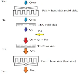
The thermoelectric cooling system in the modelling consists of a cooling box cooled by a thermoelectric cooling module (TEC) coupled with fan and heat sink in each side. Figs. 1 and 2 represent the thermodynamic cooling system analyzed.
Abstract
Figure 1: Thermoelectric cooling box.
In this cooling box, a thermoelectric cooling module (TEC) is coupled in each side with two fan/heatsink. Fig. 2 shows these components.
Figure 2: Thermoelectric cooling module (TEC) and the coupled fan/heatsinks.
Considering the steady-state condition, the principal equation from the energy balance are:
Qrem = (Tint – Tc) / ϴtc (1)
Qrem = Qc (2)
Qc = ( . I . Tc) - (0,5 R . I²) - [K . (Th – Tc)] (3)
Qrej = (Th – Text) / ϴth (4)
Qrej = Qh (5)
Qh = ( . I . Th) + (0,5 R . I²) - [K . (Th – Tc)] (6)
Qh = Qc + Pel (7)
Pel = I . V (8)
The coefficient of performance (COP) is expressed in the equation 9:
COP = Qc/Pel (9)
where:`
electrical resistance and the thermal conductance from the TEC were obtained by Ferrotec. The TEC adopted was a Ferrotec 9500/127/060 B module that has 6A of maximum current. In the cold side of the thermoelectric module is coupled a fan/heat sink with thermal resistance value of 0,7 °C/W and in the hot side of the thermoelectric module is coupled a fan/heat sink with thermal resistance value of 0,2 °C/W.
The input data range of the cooling box internal temperature (Tint) is from 0°C to 10 °C. Considering 12 V input voltage, the other parameters were found in the modelling. Then the modelling equations were calculated and graphs with different heat removed and external temperature conditions were plotted and analyzed to understand the impact of this temperature in this thermoelectric cooling system.
RESULTS AND DISCUSSION
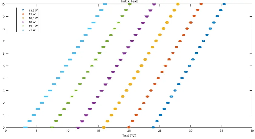
Fig. 3 shows for different values of heat removed what is the external temperature that the internal temperature of the cooling box is reached with the rated voltage.
Figure 3: Internal temperature of the box (Tint) versus external temperature (Text).
In the graph of Fig. 3 it can be seen that the heat removed from the cooling box by this thermoelectric cooling system is limited by the external temperature. In a certain external temperature, the higher is the heat to be removed, the less cold the internal temperature is obtained. Observing in another way, a certain internal temperature desired in the cooling box in a high external temperature can be reached only with a lower heat removed. This occurs due the higher external temperatures limit the dissipation of the heat rejected from the thermoelectric module.
Figure 4: Internal temperature (Tint) versus TEC cold side temperature (Tc).
The graph of Fig. 4 shows the Tc temperature necessary do attain a setpoint temperature in the cooling box for different values of heat removed. High heat to be removed implies the lower Tc required to obtain the set point cooling box temperature (Tint). In other words, for a certain temperature of the TEC cold side (Tc), the lower is the heat removed (Qrem), the lower is the Tint obtained. This is consequence of equation 1 which shows that Qrem subtracts the Tc value in its expression.
It was observed in the graphs of Figs. 3 and 4 that for this thermoelectric cooling system the internal temperature of the cooling box (Tint) is limited by its the external temperature (Text). A possibility to improve this thermoelectric cooling system substitutes the thermoelectric module to another with higher capacity. In general, thermoelectric modules obtain higher heat removed when its current is higher for the same voltage. The TEC specification normally shows the maximum current (Imax) that achieve the higher heat removed by the thermoelectric cooling module. Thereby, TEC with different Imax has different performance to reach a certain set point temperature in the cooling box.
The graphs plotted in Figs. 5, 6 and 7 show the values of heat removed from the cooling box in different external temperatures for each TEC module. Each graph is for a distinct cooling box internal temperature (Tint).
Figure 5: Heat removed (Qrem) versus Text (Tint = 10 °C).
Figure 6: Heat removed (Qrem) versus Text (Tint = 5 °C).
The graph of Fig. 6 has the same behaviour of the graph seen in Fig. 3, however each value of heat removed is obtained with lower external temperature (Text) than the graph of Fig. 3. When it needs a lower set point cooling box temperature (Tint) for the same external temperature (Text) and the same heat removed, the TEC changing sometimes is not sufficient. This can be observed especially in high values of Text where the difference of the heat removed by the differents TEC is lower.
Figure 7: Heat removed (Qrem) versus Text (Tint = 0 °C).
The graph in Fig. 7 presents the same behavior of higher heat removed (Qrem) by TEC with higher Imax at the same external temperature and this difference increases for lowers values of Text. This probably occurs due the fact that to achieve a lower temperature in the cooling box (Tint) demands more heat rejected in the TEC hot side and sometimes the external temperature limit the dissipation of this heat. For 0°C value of Tint, for thermoelectric system reach the same heat removed (Qrem) at sa me Text value and 10 °C value of Tint is not more possible as can be seen comparing the graphs of the Figs. 5 and 7.
The results of the thermodynamic model elaborated of the thermoelectric system showed that the external temperature (Text) limited the cooling performance. Higher external (Text) temperatures imply in lower cooling capacity and less cold internal temperatures (Tint) are reached.
Changing the thermoelectric cooling module (TEC) is a possible solution to improve the cooling effect. However is important to check if the external temperature doesn’t limit the internal temperature (Tint) set point of the cooling box.
ACKNOWLEDGEMENTS
The first author would like to thank CAPES for the Master’s scholarship. The second author would like to thank FACEPE for the scientific research scholarship.
REFERENCES
Ferrotec. Thermoelectrical Reference Guide.
Eslami, M., Tajeddini, F., Etaati, N., 2018. Thermal analysis and optimization of a system for water harvesting from humid air using thermoelectric coolers. Energy Conversion and Management, Vol. 174, pp. 417-429.
Lundgaard, C., Sigmund, O. (2019). Design of segmented thermoelectric Peltier coolers by topology optimization. Applied Energy, Vol. 239, pp. 1003-1013.
Mirmanto, M., Syahrul, S., Wirdan, Y. (2019). Experimental performances of a thermoelectric cooler box with thermoelectric positions variations. Engineering Science and Technology, an International Journal, Vol. 22, pp. 177-184.


![Appoximation assisted [sic] estimation of eigenvectors under quadratic loss](data:image/gif;base64,R0lGODlhAQABAIAAAP///wAAACH5BAEAAAAALAAAAAABAAEAAAICRAEAOw==)