Wind Energy
Leasing Handbook
Wind Energy
Leasing Handbook
E-1033
Oklahoma Cooperative Extension Service
Division of Agricultural Sciences and Natural Resources
Oklahoma State University
In cooperation with:
Extension
Handbook funding made possible by a grant from the USDA Risk Management Agency through the Southern Risk Management Education Center – Project RME-MD-303936.
Oklahoma State University, in compliance with Title VI and VII of the Civil Rights Act of 1964, Executive Order 11246 as amended, Title IX of the Education Amendments of 1972, Americans with Disabilities Act of 1990, and other federal laws and regulations, does not discriminate on the basis of race, color, national origin, gender, age, religion, disability, or status as a veteran in any of its policies, practices or procedures. This includes but is not limited to admissions, employment, financial aid, and educational services.
Issued in furtherance of Cooperative Extension work, acts of May 8 and June 30, 1914, in cooperation with the U.S. Department of Agriculture, Director of Oklahoma Cooperative Extension Service, Oklahoma State University, Stillwater, Oklahoma. This publication is printed and issued by Oklahoma State University as authorized by the Vice President, Dean, and Director of the Division of Agricultural Sciences and Natural Resources and has been prepared and distributed at not cost to the taxpayer. 1212. GH.
Table of Contents
Understanding the Electrical Power Industry ... 1
By Shannon L. Ferrell and Rusty Rumley What is electricity? ... 1
How is electricity generated and moved? ... 1
How do electrical generators convert other forms of energy into electricity? ... 4
What is the electrical grid? ... 8
How do power companies buy power from generators and sell it to customers, and how are these prices set? .. 15
How do electric companies price power? ... 19
How does wind fit in the electrical power industry? ... 20
Understanding the Wind Power Industry ... 23
By Shannon L. Ferrell, Steve Stadler, and Rusty Rumley What is wind, and what causes it? ... 23
Why is there so much wind in Oklahoma?... 24
How is wind measured and analyzed? ... 24
How has wind been used to generate power in the past? ... 29
How do modern wind turbines work? ... 31
What do wind developers consider in locating wind energy projects? ... 34
How do power companies use electricity from wind? ... 37
How do companies and individuals invest in wind energy projects? ... 38
Understanding Wind Energy Agreements ... 39
By Shannon L. Ferrell and Rusty Rumley The wind energy agreement ... 39
How are wind energy agreements structured? ... 39
Why do wind energy agreements have long durations? ... 42
What are your obligations as a landowner under the wind energy agreement?... 43
How are payments set by the wind energy agreement? ... 45
What happens when the wind energy agreement is over? ... 47
How can landowners manage the expense of legal assistance?... 47
How to find an attorney to help you analyze your agreement ... 48
Impacts of Wind Leasing Projects ... 49
by Rusty Rumley, Charles Cunningham, and Shannon L. Ferrell Introduction ... 49
What environmental impacts can a wind energy project have on its surroundings? ... 49
How does the Endangered Species Act impact wind energy projects? ... 50
How does the Clean Water Act impact wind energy projects? ... 51
What is the doctrine of nuisance? ... 53
What are the nuisance impacts of wind turbine noise and shadow flicker? ... 54
What are the aesthetic impacts of wind energy projects? ... 55
Are there dangers to life and property posed by wind energy projects? ... 56
What is the doctrine of trespass? ... 57
How are injunctions used to prevent construction of wind energy facilities? ... 57
What are the economic impacts of a wind development project? ... 58
Understanding
the Electrical Power Industry
Objectives
After reading this section, you will un-derstand:
1. What is electricity?
2. How is electricity generated and moved through electrical circuits? 3. How is electricity measured? 4. How do electrical generators
con-vert other forms of energy into electricity?
5. How does the electrical grid con-nects generators, transmission as-sets and consumers together? 6. How is electricity transmitted from
the generator to the user?
7. How do electric companies buy and sell power?
8. How do electric companies price power?
9. How does wind fit in the electrical power industry?
What is electricity?
Electricity is an immensely important part of modern life. We use electricity to keep us cool in the summer and warm in the winter, to provide light in the dark, to cook our food, to power the machines that make other products, to process and move agricultural goods, and increasingly, to get us from place to place. But what is electricity, anyway?To answer this question, we start with the atom. All matter is made up of atoms. Atoms, in turn, are made up of three basic kinds of particles. The nucleus, or center, of the atom is made up of protons and neutrons. Electrons orbit around the nucleus. Importantly, pro-tons have a positive (+) charge and electrons
have a negative (-) charge (neutrons have no charge). As long as the atom has the same number of protons and electrons, the positive charge of the protons and the negative charge of the electrons balance each other.
Strong forces hold the nucleus of the atom together, but the application of a relatively small amount of energy to the atom can knock an electron out of its orbit. Once we do this, the atom has more protons than electrons and has a positive charge. Similarly, the electron now represents a lone negative charge. The elec-tron wants to find another nucleus to orbit, and once it does, it transfers the energy it carries to that atom. That energy transfer may knock another electron out of its orbit, and so on. As we keep applying energy, more and more electrons jump from atom to atom. This flow of electrons is what we typically call electricity or current.1
How is electricity
generated and moved?
To move electrons, we need some source of energy to act on the atoms and knock the elec-trons from one atom to another. We also need a pathway of atoms for the electrons to move along; electrons must have a new atom to orbit or they will strongly resist being moved.
Generally speaking, there are two ways to deliver the energy that moves an electron from one atom to another. Applying a magnetic field to the atoms can move the electrons from one atom to another since electrons react strong-ly to such fields. This is the process used in both electric motors and electric generators, as a magnet is moved through an electrical field or vice versa. In a way, this is also how solar cells (also called photovoltaic cells) generate
1 An abundance of electrons that are not flowing is often called static electricity.
electricity. Light particles called photons are actually tiny packets of electromagnetic ener-gy, which strikes the atoms in the cell, knocking electrons from atom to atom and generating an electrical current.
The other way to cause electrons to move from atom to atom is by a chemical reaction that causes the substances in the battery to exchange electrons. Batteries are made up of three basic components: (1) a cathode which forms the positive side of the battery and is made up of a substance that wants to accept electrons, (2) an electrolyte, which is a sub-stance that makes the exchange of electrons easier, and (3) an anode which forms the neg-ative side of the battery and is made of a sub-stance that wants to give up electrons. For example, in an alkaline battery, the cathode is manganese dioxide, the electrolyte is zinc chloride, and the anode is zinc. The chem-ical process in the battery causes an excess of electrons at the negative end of the battery, and these electrons want to move away from one another. Since they are prevented from moving toward the positive end of the battery by a separator within the battery, they will move through a circuit when one is connected to the battery.
While magnetic fields and chemical reac-tions are the most common ways we create a flow of electrons, there are other ways elec-trons can be moved as well. For example, when pressure is applied to some substances, they generate very small amounts of electrical cur-rent. This is how microphones and some elec-tronic scales work. In other substances, apply-ing heat can create a small flow of electrons, and this is how some thermometers measure temperature. The processes of using pressure and heat to cause electrons to flow can be very useful, but they produce only tiny amounts of electricity.
Once we have created an abundance of electrons, we need to provide a path for them to move along in order to accomplish any work. Conductor materials such as copper, aluminum, and iron (or steel) are made up of atoms with electrons that easily leave their orbits and move to other atoms make the flow of electrons pos-sible. A pathway for the electrons to follow from their source (a generator or battery) through a conductor and back to their source is called a circuit. Electrons must have a complete circuit
before they will flow. This is because electrons do not want to move from one atom unless there is another atom nearby. Otherwise, they will go nowhere. To see this, connect a wire from one end of a battery to a switch and a bulb, and then connect the switch and bulb with a wire attached to the other end of the battery. Close the switch, and electrons flow through the cir-cuit lighting up the bulb. Open the switch and nothing happens because the electrons cannot flow.
If the atoms of a material do not readily give up their electrons, this hampers the flow of electricity, and we call the material an insulator. Insulators serve a valuable role in moving elec-tricity too, as they form barriers that prevent the electrons from going where we do not want them to go.
How is electricity measured?
As we discuss electrical systems, we need some terms to describe what happens to the flow of electrons. As we do this, it might help to think of something else that flows: water. So, before we begin, think of a water system with a water tower on top of a hill, a series of pipes,and a number of taps for its customers.
One thing we care about with a water sys-tem is the amount of flow and we often measure flow in gallons per minute. In other words, we ask how much water passes by a given point during a given amount of time. With electricity, we are dealing with the flow of electrons, so it makes sense to measure how many electrons flow past a given point during a given amount of time too. Instead of gallons per minute, we must count electrons per second. Since elec-trons are so very small, we must count a lot of them. We call 6.289 x 10¹⁸ electrons (or more
than sixty quintillion – that is a 6 with eighteen zeroes after it) a coulomb. A coulomb passing by a given point in one second is called an am-pere which is usually shortened to amp. You may also see it represented by the symbol “A.” Another thing we care about in a water system is the amount of pressure, because pressure, combined with flow, can sometimes determine how much can be accomplished by the water. We often measure water pressure in pounds per square inch. Electrons do not exert this kind of pressure on their conductors or on devices that use them, but there is an
analo-gy that can help us. How do we move water through pipes? We either put a water tank in a high place so that gravity wants to pull the water down and away from it, or we put pumps in the system to push it along. In other words, we create something that puts pressure on the system, knowing that water wants to move from an area of greater pressure to an area of less-er pressure. When watless-er is raised in a watless-er tank or put under pressure, we say that it has potential energy. That energy isn’t released un-til the water starts moving. The same principle holds true for electrical circuits. Electrons try to repel each other (remember that like charges repel, and opposite charges attract), so where we have an abundance of electrons, they want to get away from each other to an area where there are not as many. Until they start moving, the electrons only have potential energy. Just as pressure on a water system makes the wa-ter want to move, a difference in electron con-centrations between two points in an electrical circuit creates a difference in the potential flow of electrons between those two points that tries to push electrons between those points. That force is called electromotive force or “EMF.” We measure this force, or pressure, with units called volts and represented by the symbol “V.” In electrical equations, this force is represent-ed with either the letter “E” (for electromotive force) or “V” (for voltage).
So how do we define what a volt is? To an-swer that, we have to talk about the other con-cept in measuring electricity: resistance. In a water system, there may be a number of things that try to prevent the flow of water through the pipes. Friction along the walls of the pipes or blockages can slow the flow of water. Similarly, if we place something that is not a good con-ductor in an electrical circuit, we will slow the flow of electrons. We measure the ability of a substance to resist the flow of electrons in units called ohms. This is often represented with the Greek letter omega, or W. In electrical
equa-tions, resistance is represented by the letter R. All substances – even the very good conduc-tors – have some level of resistance.2
So how do these factors work together? We define a volt as the amount of pressure or force needed to push one coulomb through one ohm of resistance for one second. This means you can define an ohm as the amount of resistance that would allow a current flow of one ampere if one volt of force were applied. The relationship between current (flow), voltage (pressure) and resistance is always constant in an electrical system, and can be expressed like this:
This is called Ohm’s Law and governs how all of our electrical circuits work. Once you understand this relationship, many aspects of electrical systems become clear.
Before we leave this discussion, we need to address one more aspect of measuring elec-tricity – the capacity of elecelec-tricity to do work. Work in the realm of physics is defined as force acting on a mass across a distance (for exam-ple, when you push a weight over a given dis-tance, you are producing work). In discussing electrical circuits, we define work as the action of an electromagnetic field moving electrons through a resistance. When one ampere of cur-rent moves though an electrical potential dif-ference of one volt, this is a watt (“W”). Work performed over a given amount of time consti-tutes energy and in the electrical industry, en-ergy is often measured in watts over time. For example, doing one watt of work (power) con-tinuously for an hour (energy) is a watt-hour. Doing one thousand watts of work continuously over an hour would be a kilowatt-hour (kWh) of energy. The use of electricity for homes and businesses, and the production of energy by small generators is often measured in kWh. For example, the average U.S. home has a peak electrical demand of between three and five kilowatts.3 If a home used this amount of
ener-gy over an hour, it would consume three to five kWh of energy. Doing one million watts of work for an hour would be a megawatt-hour (MWh) of energy. The use of large industrial facilities, and the production of energy by large utility generators is often measured in MWh.
2 There are certain substances called superconduc-tors that have almost no resistance to the flow of electrical current, but as of now they are relatively rare and are not frequently used in producing and
transmitting large amounts of electricity. 3 Understanding Today’s Electricity Business, p. 3. 3
How do electrical
generators convert
other forms of energy
into electricity?
We know from the previous discussion that to make electrons move through a circuit, we need to do something that causes a buildup of electrons under pressure at one point so that we can push those electrons through the circuit and then back to their source. How can we do this?
We discussed above that there were pri-marily two ways to generate current – through using magnetic fields and through chemical processes. Chemical processes tend to pro-duce relatively smaller amounts of current, so while they may be ideal for providing portable power in the form of batteries, they generally cannot provide the power needed for larger de-mands like multiple homes, industrial machin-ery, and so on. Thus, we need something capa-ble of producing much more current at higher voltages.
Long ago, scientists discovered a principle called Faraday’s Law. Faraday’s Law tells us that if we pass a conductor through a chang-ing magnetic field, a voltage is created. In oth-er words, the electromagnetic field acts on the electrons in the conductor, creating the pres-sure that makes the electrons want to move. To see this in action, connect a length of wire to a voltmeter and then pass a magnet near the wire. As the magnet moves past the wire, the voltmeter will move, indicating that a volt-age was created. If you hold the magnet still, though, nothing happens. Thus, movement through the magnetic field is required.
If you kept experimenting with this system, you might find that there were a couple of ways to increase the voltage you observe. You could create some coils in the wire and you would see that with every coil that passes through the magnetic field you are increasing the amount of voltage produced. This is because with each coil you are increasing the length of wire passing through the magnetic field in a given amount of time. You could also move the wire by the magnet faster and see that this too in-creases the voltage. Using a stronger magnet would also increase the voltage.
What you have done is create a very simple electric generator. The massive electrical gen-erators used by utility companies to produce power for thousands of customers at a time use exactly the same principles – they just operate on a larger scale. In a typical utility generator, a series of tightly wound wire coils called a sta-tor are placed around a spinning electromag-net called a rotor. The only difference between this and our homemade generator is that we moved the wires and the magnet stayed still. In the generator the wires stay still and the mag-net moves. By spinning the rotor inside the sta-tor, we are constantly moving the magnet past the coils and constantly generating a voltage. Importantly, this voltage changes as the rotor moves past the stators – this will be discussed later.
As we learned from our experiments, mov-ing the coils and magnet relative to each other is what produces the voltage and thus current, so we need to find some source of energy that can be continuously applied to the rotor to keep it spinning. We also learned that the faster we move the coils and magnet, the more voltage, and thus current, we can produce. This is what makes generators so flexible; we can use a number of energy sources to generate electric-ity so long as we can convert that energy into a rotating motion to propel our generator.
Where can we find this energy? It can come from a number of sources, and we will discuss some of the most common forms below.
Coal
The largest single source of energy for the United States is coal. In a typical coal gen-eration plant, coal is burned in a combustion chamber to release heat. Temperatures in these chambers reach well over 1,000 F, and water is then passed through tubes in a boiler coupled to the combustion chamber to turn the heat into superheated steam at pressures of more than 2,000 pounds per square inch (psi).
4 This steam is directed through the blades of a
turbine, where its tremendous pressure pushes the blades, causing them to rotate. The turbine blades are connected to a rotating shaft, which is connected to the rotor of a generator. As the
shaft spins, the rotor moves past the stator, generating electricity.
Because it takes time to get a combustion chamber and boiler up to their most optimal operating temperatures, coal generation plants are most efficient when they can run at a con-sistent level, day and night. Conversely, they become less efficient when they are forced to increase or decrease their output. This impacts how they are used in conjunction with other generators, as we will discuss below.
Nuclear
Nuclear power plants work in much the same way. The difference is that instead of burning coal, a controlled nuclear reaction is used to generate the heat used to create steam. In a nuclear reactor, highly-refined nuclear fuel (usually enriched uranium) is used. The atoms of uranium have a very large number of protons and neutrons in their nucleus, and this nucle-us is very unstable as its neutrons frequently break free and release energy from the nucleus as a result. These neutrons then slam into oth-er nearby atoms, breaking apart their nuclei as well, forming a chain reaction. These reactions generate a tremendous amount of heat, which is used to convert water into steam. The reac-tion is controlled using control rods that absorb the neutrons and slow down the reaction. This is the primary difference between a nuclear re-actor and a nuclear weapon. In nuclear weap-ons, the reaction is uncontrolled and rapidly converts large amounts of the fuel into energy. In a nuclear reactor, fuel is used very slowly, which is why a small supply of fuel may last a reactor for many years.
Nuclear plants can take even longer than coal fired power plants to reach their optimal temperature, and this too affects how they are used to produce power.
Natural Gas
Natural gas can also be burned as a fuel to create heat make power in basically the same way as coal or nuclear power. These genera-tors are sometimes called natural gas thermal generators. Like coal-powered generators, these generators can also take some time to bring into operation.
However, some electrical generators use natural gas in a different way. Natural gas can be used as a fuel for turbines almost identical
to those used as jet engines (which are them-selves turbines). Natural gas is burned in the combustion chamber of the turbine, causing the turbine blades to spin. As with other tur-bines, these blades are connected to a shaft that is used to spin the generator’s rotor. These generators can be brought into operation very quickly, and can be used to provide power when it is needed on short notice. These erators are sometimes called gas turbine gen-erators.
There is another form of electrical gener-ation from natural gas that recycles some of the thermal energy from combustion of the natural gas. In these systems, natural gas is first burned in a gas turbine generator to pro-duce electricity. This process creates heat as well, and this heat is then used to turn water into steam that is then used to propel a steam turbine that produces additional power. These systems are called natural gas combined cycle generators.5
Water (Hydropower)
Water can be used to turn a generator as well. For centuries, mills placed water wheels in the flow of a stream of river, allowing the force of the moving water to push the wheel and thus rotating millstones or other machinery. That basic principle is slightly modified to power modern hydroelectric power plants. Typically, a dam is placed across a river to raise the ele-vation of the water. With this increase in eleva-tion, the water has more potential energy (as discussed above). This water is then released through a water outlet, where it flows down a tube called a penstock and into the blades of a water turbine. As with all the other turbines dis-cussed, this causes the blades to rotate a shaft which is connected to the generator, providing electrical power.
Wind
With all this talk of mechanical forces push-ing the blades of a turbine to generate elec-tricity, you can probably guess how a wind tur-bine works; the wind passing by the blades of the turbine turns the rotor. This is just like the other kinds of generators, with two exceptions. First, since the blades of a wind turbine are so 5 Understanding Today’s Electricity Business, p. 39. 5
large, they must turn at a relatively slow rate to avoid being damaged. As a result, the rotor is connected to a transmission that turns the slow but powerful rotation of the blades into a much faster rotation that is used to move the rotor inside the generator. Second, wind cannot be controlled and thus the turbine can only gen-erate power when wind is available. For a fuller explanation of how wind turbines work, see the chapter on the wind power industry.
The Power Portfolio
Different circumstances suit some genera-tor technologies better than others. As we dis-cussed above, generators that rely on heat take a long time to reach their most efficient operat-ing state, but they may also be the least expen-sive to operate. On the other hand, natural gas turbines and hydropower can be operational in a matter of minutes, but natural gas generators can sometimes be costly to operate, and hy-dropower dams may need to conserve water. Since, at least right now, there are no technol-ogies that allow us to store electricity for later use (at least, at the scale needed by utilities), and we can only use wind power when the wind is blowing. All of this means that utilities use a portfolio of generator technologies to provide their customers with power. This means that they rely on a combination of different
gener-ator technologies used in different amounts at different times to make sure that their custom-ers have power when they need it, and at the lowest cost.
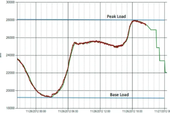
Utilities must make sure that their custom-ers have the power they need when they need it. This is not easy because electrical demand is not the same throughout the day. At night, when people are asleep and many business-es are closed, lbusiness-ess power is used. As people wake up and go to work, more energy is used. In the summer, electrical demand peaks in the late afternoon and early evening hours as tem-peratures rise and air conditioning is needed. This change in electrical demand over a day is called the load curve (Figure 1).
As you look at this curve, you see that there is a certain level of electricity that is always needed – electrical demand never dips be-low this amount. This is called baseload. Since this amount does not vary greatly, utilities often use generators powered by thermal resources, such as coal, nuclear, and natural gas thermal generators to provide this power. Some hydro-power and renewable resources may also be used in baseload generation.
Beyond baseload, we can also see that there is another stage, if you will, where more electricity is demanded than during the base-load periods, but where the demand rises and
Figure 1. Load Curve for the Southwest Power Pool. Source: Southwest Power Pool, http://www.spp.org/RealTimeLoad.html
falls slowly enough that generators have some time to respond. This is called intermediate load. These demands are often met with natural gas thermal generators, natural gas combined cycle generators and with hydropower.
Last, at the top of the curve, we see what is called peak load. This demand can change very quickly and puts the most strain on the electrical system. Think about 5 p.m. on a hot summer day. Everyone starts to arrive home from work and notices that their home is hot. They all turn on their air conditioners (which is often the largest single electrical load for their house) at about the same time. Demand for electricity across the entire area then sharply rises. As a result, the electrical utilities must be able to quickly respond with the amount of electricity needed to meet this demand. They need electrical generators that can be brought on-line quickly, so they often use natural gas turbines and hydropower for these periods.6
Because sources used to generate peak pow-er may not be as efficient as othpow-er sources, and due to market conditions, peak power can be very expensive compared to baseload power.
Where does wind fit in this discussion? As discussed above, utilities have to use wind power when it is available. Thus, the utilities need very accurate weather forecasts to help them know how much wind power will be avail-able in the day ahead. They can then adjust the generation available from other resources to save other types of fuels when wind pow-er is available. Gas turbine units are most of-ten used for this task, since they can respond rapidly if the wind should stop blowing. Since Oklahoma has a large number of natural gas powered generation, this makes wind power a good fit for many of our utilities.
While research continues into a number of technologies that would allow us to store power when electrical demand is low and release it when demand is high, there are no such tech-nologies that can operate at utility-scale right now. That means that utilities must coordinate their generation with demand in real time. Re-gardless of what energy source is being used to supply power, there must be sufficient
re-serve power available to make sure all custom-ers have the power they need should a gener-ator go offline for any reason. A certain amount of additional generation capacity must be available at all times and on a moment’s notice to step in and provide additional power. This capacity is provided by generators that can respond quickly to changes in demand, and is often called spinning reserves because the generators are kept operational and running (spinning) when they are on call.
Someone has to coordinate all of these dif-ferent kinds of generators to make sure enough electrical power is available to everyone who needs it. This is called dispatching the gener-ators. In Oklahoma and the surrounding area, this is accomplished by an organization called the Southwest Power Pool (SPP). When it is de-termining which generators need to be used at a given time, SPP is functioning as an electrical reliability organization. SPP also carries out a number of other roles in our region, which will be discussed later.
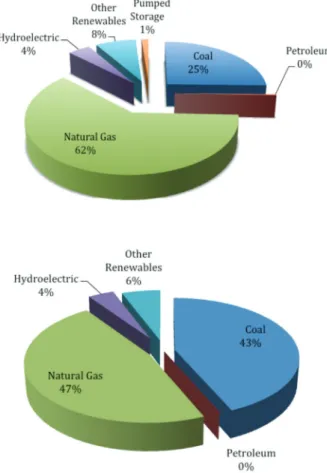
Figure 2 shows the amount of capacity Oklahoma’s utilities have in each type of elec-trical generation and how much power was generated by each type. As you will see, Okla-homa has more natural gas powered capacity than any other type, but we use more electricity from coal powered generators (which are used to provide baseload). Also note the amount of electricity that is now provided by wind power. So far, we have talked about how utilities use different types of electrical generation to provide power to their customers. Sometimes, utilities also use demand response systems as an alternative to generating more power. In such cases, these systems allow the utility to request (or in some cases, command) custom-ers to stop using certain electrical equipment. Customers usually receive reduced rates or other considerations for participating in these programs. This means less electrical power is required. Helping consumers use less power means the utility may not have to build new generating facilities, thus saving them and their customers additional costs. It also can reduce the emissions of greenhouse gases. This is why some utilities offer rebates on energy-efficient appliances or other incentives that encourage power conservation by their customers.
6 For a general discussion of how the load curve and generation dispatching is usually accomplished to meet it, see Understanding Today’s Electricity Busi-ness, pp. 47-48.
What is the
electrical grid?
Now that we have talked about the different ways electrical power can be generated, we need to talk about how to get that power to its users. To do that, we need a system of electri-cal circuits capable of reliably delivering large amounts of electrical power to a wide variety of customers. We call that system the electrical grid or the power grid.
We often talk about the national power grid, but that is not really accurate, since there is not really a continuous nation-wide network of electrical transmission lines. Instead, there
are a series of regional networks called inter-connections. All of these interconnections are overseen by an organization called the North American Electric Reliability Council, or NERC. NERC is not a government agency, but the gov-ernments of the USA and Canada have given it the authority to oversee the operation of the regional interconnections. There are four in-terconnects in North America. These are the Quebec Interconnect, the Eastern Interconnect (of which Oklahoma is a part), the Western In-terconnect and the Texas InIn-terconnect (some-times called the ERCOT Interconnect, named after the Electric Reliability Council of Texas). These interconnections operate inde-pendently, although almost all of them now have a limited number of connections with their neighbors to allow for the sale of power among them. These connections between intercon-nects require complex and expensive equip-ment as the phase and frequency of the power between the two interconnections must be syn-chronized.
Interconnections are composed of groups such as Independent System Operators (ISOs), Regional Transmission Operators (RTOs) and Regional Reliability Councils. These are non-profit organizations that operate under the jurisdiction of the Federal Energy Regulatory Commission (FERC).7 They are managed by a
board of directors made up of representatives of the generators, transmission systems, pow-er marketpow-ers and govpow-ernment agencies in their territories.
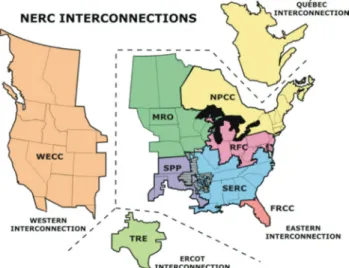
ISOs and RTOs are responsible for coordi-nating the operation of the electrical transmis-sion systems within their jurisdictions. A map showing the interconnections and their ISOs/ RTOs is shown in Figure 3.
While ISOs and RTOs carry out the import-ant task of coordinating the transmission of electrical power, the Regional Reliability Coun-cils must coordinate the generation of power (which also includes the reliability and security of such generation). There are eight such coun-cils in NERC.
SPP operates in Oklahoma, Kansas, and in parts of Texas, Arkansas and Louisiana. As you *In both charts, Other renewables includes all renewables
other than hydroelectric, but in Oklahoma, wind compris-es almost all of this category.
Figure 2. Oklahoma Generation Fleet and Production.
Source: Energy Information Administration Oklahoma electricity profile, available at http://www.eia.gov/electric-ity/state/oklahoma/
7 The exception to this is ERCOT. FERC has jurisdic-tion over the interstate transmission of power, and since all of ERCOT is within the borders of Texas, it does not engage in the interstate transmission of power.
can see from the Tables 1 and 2, SPP serves as both the RTO and Regional Reliability Coun-cil within its territory. This means SPP must ac-curately forecast how much power will be de-manded by customers, coordinate generators to make sure that sufficient power is available and plan routes along transmission lines to make sure the power gets where it needs to go. SPP also is charged with doing this in a cost-ef-fective way to make sure electrical rates stay at reasonable levels for customers.8
How is electricity
transmitted from the
generator to the user?
Generally, a vast network of high voltage power lines are used to accomplish this task.
Why do we use
such high voltages?
When people use electrical power, they are trying to accomplish some form of work with that power. They are trying to generate heat, move machinery, create light, operate comput-ers and so on. In our previous discussion, we said electrical work (and thus, power ) is often measured in watts, and that a watt is defined as one ampere of current moving though an elec-trical potential difference of one volt. If we were to express this as an equation, it would look like this:
So, if we want to get a large amount of pow-er to electrical uspow-ers, we have to eithpow-er increase the amount of voltage or increase the amount of current. What would happen if we increased the amount of current?
We discussed the fact that virtually all elec-trical conductors have some amount of resis-tance that restricts the flow of electrical cur-rent through them. The amount of power lost to resistance in a conductor is a function of the amount of current and the resistance:
Figure 3. NERC Interconnections. Table 1. NERC NERC ISOs and RTOs.
ISOs RTOs
Alberta Electric Midwest Independent System Operator Transmission System
(AESO) Operator (MISO)
California ISO (CAISO) ISO New England (ISONE)
Electric Reliability PJM Interconnection Council of Texas (PJM)
(ERCOT)
Independent Electricity Southwest Power Pool System Operator (SPP)
(IESO) (Ontario Hydro) New York ISO (NYISO)
Source: Electric Power System Basics, p. 183
Table 2. NERC Regional Reliability Councils Electric Reliability Council of Texas, Inc.
(ER-COT)
Florida Reliability Coordinating Council (FRCC) Midwest Reliability Organization (MRO)
Northeast Power Coordinating Council (NPCC) ReliabilityFirst Corporation (RFC)
SERC Reliability Corporation (SERC) Southwest Power Pool, Inc. (SPP)
Western Electricity Coordinating Council (WECC)
Source: Electric Power System Basics, p. 183 8 Understanding Today’s Electricity Business, p. 90. 9
This tells us resistance increases as a square of the amount of current we try to pass through a conductor.
This has a tremendous impact at the scales we use when discussing the transmission of power from utilities to customers. Let’s say we are an electrical utility and we need to transmit one megawatt (i.e. 1,000,000 watts) of power to our customers. Power equals voltage times current, so we can use either higher voltages and lower currents, or lower voltages and high-er currents to get this numbhigh-er. Now, let’s say we have two choices: we can choose two volt-ages, a ten kilovolt (kV) line or a 100 kV line. To deliver a megawatt of power on the 10 kV line, we would need to use 100 amperes of current (10,000 volts x 100 amperes = 1,000,000 watts). To deliver a megawatt of power on the 100 kV line, we would need to use 10 amperes of cur-rent (100,000 volts x 10 amperes = 1,000,000 watts). Both lines have a resistance of 10 ohms (10 W).9 How much power would we lose from
each line?
From this example, you can see using high-er voltages means we lose much less powhigh-er that we would by using higher currents. 10
Besides the efficiency issue, using higher currents and increasing resistance causes oth-er problems. Resistance in a conductor almost always manifests itself as heat due to the fact that more and more electrons are bumping into each other, causing frictional heat. If we tried to transmit the amount of power needed by all of a utility’s customers by increasing the amount of current, we would generate so much heat electrical lines would sag into trees and struc-tures or melt (on days when electrical demand is very high, there is a lot of current flowing through the wires, and this phenomenon can occur). The only alternative would be to use much bigger wires. Such wires would be much more expensive, and would also require much larger transmission towers and poles.
So, using higher voltages gives us a more efficient electrical transmission system. By do-ing this, we can keep the current levels rela-tively low while still delivering the same amount of power. And as you see from the equations in Table 3, increasing voltage allows us to
pro-vide more power without any increase in resis-tance, which means less heat. This means in-creasing voltage rather than current allows us to use smaller wires, which allows us also to have smaller transmission towers and poles. All of this saves money for both electrical utilities and their customers.
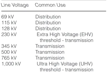
Given this, we often classify electrical lines with voltages of 69 kV or more as transmission lines. Table 4 shows the most common sizes of transmission lines and their uses.
Using high voltages also decreases the amount of land taken up by transmission sys-tems. One high voltage line can carry the same amount of power as many smaller lines, and thus only one smaller right-of-way is needed from landowners (Figure 5).11
Table 4. Common Transmission Line Voltage and Use.
Line Voltage Common Use
69 kV Distribution 115 kV Distribution 128 kV Distribution
230 kV Extra High Voltage (EHV) threshold - transmission 345 kV Transmission
500 kV Transmission 765 kV Transmission
1,000 kV Ultra High Voltage (UHV) threshold - transmission 9 This discussion adapted from Basic Electricity, p.
3-5.
10 This discussion taken from Basic Electricity, p. 3-6. 11 Electric Power Systems, p. 49.
Table 3. Comparison of Line Losses.
10 kV Line 100 kV Line
Power Lost = I2 x R Power Lost = I2 x R
Power Lost = Power Lost = (10)2 x 10
(100)2 x 10
Power Lost = Power lost = 1,000 100,000 watts watts
Why do we use alternating
current to transmit power?
We have established that high voltages are necessary for transmitting power – hence we need the ability to increase (or step up ) voltag-es to transmit large amounts of power over long distances. Once power reaches its destination, though, we also need to reduce ( step down ) the voltage to a level that we can use in our homes and businesses. If we use alternating current for our power transmission, we can use a device called a transformer to increase or de-crease these voltages (Figure 4).
The importance
of transformers
Earlier, we noted that Faraday’s Law tells us a changing magnetic field creates a voltage in a conductor. We also said passing an electrical current through a conductor creates a mag-netic field around that conductor. Using these principles together, we can induce a voltage by passing a current through a conductor (the primary ) whose magnetic field cuts across an-other conductor (the secondary ). If we contin-uously vary the magnetic field produced by the primary, we also can continuously create a volt-age in the secondary. We also can strengthen this transfer between the primary and second-ary by linking them with a magnetic material, such as iron.
The number of coils in a wire affect how many magnetic field lines intersect the wire in a given space; this principle is what enables transformers to work. If both the primary and secondary had the same number of coils, the voltage created in each of them would be basi-cally the same. However, if the number of coils in the primary were different than the second-ary, the voltage would have to change. The re-lationship between the voltages in the primary and secondary is the ratio between the number of coils in the primary the secondary. If there are 100 turns in the primary and 1,000 turns in the secondary, then the ratio is 100:1,000 Figure 4. Diagram of electrical system
Source: New Zeland Ministry of Business, Innovation and Employment, http://www.med.govt.nz/sectors-industries/ener-gy/electricity/industry
Figure 5. Diagram of Transmission Configu-rations
Source: SPP, http://www.spp.org/publications/Intro_to_ SPP.pdf
or 1:10. This means the voltage created in the secondary will be 10 times the voltage in the primary. This would be a step up transformer. On the other hand, if we reversed things, with 1,000 turns in the primary and only 100 in the secondary, the ratio would now be 10:1, and the voltage in the secondary would be 10 times less than the primary.
So, we can see how changing the voltage of power lets us adapt the flow of power to the needs of both transmission and the individual user. But what does this have to do with using alternating current (ac) power rather than di-rect current (dc)?
First, we have to explain the difference be-tween direct and alternating current. Direct current, as the name implies, flows in one di-rection constantly. Alternating current, on the other hand, alternates the direction in which it flows. In the United States, electrical systems are designed around a system where the elec-tricity completely changes its direction of flow sixty times per second (this is referred to as 60 Hertz or 60 Hz). These changes in direction do not occur instantly, though – the electrons begin to flow in one direction, slow down, and then begin to accelerate in another direction. If you were to measure this on a graph, it would look like Figure 6.
We call this a sine wave. This change in current is what enables us to use transform-ers to change voltage. If we pass ac current through the primary coil of a transformer, there is continuous change in the current. And since there is continuous change in current, there is continuous change in the magnetic field.
Ac-cording to Faraday’s Law, changing magnetic field induces current. If we used direct current in our transformers, there would be no change in the magnetic field, and thus no current would be induced by the secondary coil.
Using dc power
for transmission
Changing the voltage of dc power at the scale we need for transmission involves very complex and expensive equipment, and is gen-erally impractical except for certain long-range transmission applications. If a large amount of electrical power needs to be transmitted a long distance, a dc line does have some ad-vantages. First, it only needs two conductors rather than the three needed for ac electrici-ty. This means less right-of-way is required, and towers can be constructed with less ex-pense. Second, dc power has no frequency (as opposed to ac power, which has a 60 Hz frequency). This means it can be used to con-nect power systems that are not synchronized without expensive synchronization equipment. Third, dc transmission systems are used just to transport large amounts of power; they are not used to provide power to individual customers. This means the expensive equipment needed to convert dc to ac power is limited to the two ends of the transmission lines, which reduces cost.
The electrical
transmission system
Now that we have discussed some of the basics of how we transmit electrical power from the generator to the user, let’s talk about the electrical transmission system and its pieces.
Generator station
At the generator station, the utility will have the generator supplying the electricity, equip-ment to make sure that the power created is at the right frequency (60 Hz), and large step up transformers to increase the voltage from that of the generator to the voltage needed for transmission. The equipment needed to in-crease the voltage and to send the electricity along the proper transmission lines is often lo-cated in an area known as a switchyard. Figure 6. Diagram of AC sine wave.
Transmission lines
and towers
Three materials are most commonly used to build electrical transmission lines (also called wires or cables): copper, aluminum and steel. Copper is a very good conductor, is durable, and is relatively inexpensive. Aluminum is not as good a conductor as copper, but it is lighter. Steel is not as good a conductor as copper or aluminum, but it is strong and is often bundled together with the other two to add strength to the transmission cable.12 Multiple cables may
be bundled together to increase the capacity of the line.
Running transmission lines above ground (this is also called overhead ) keeps the trans-mission lines from coming into contact with any-thing on the ground that could short out the line (that is, create an electrical connection to the earth that would disrupt the circuit). Keeping transmission lines high overhead also reduces the risk of structures, trees, animals or people being injured by coming into contact with the lines. There are disadvantages to overhead lines, though. Keeping lines overhead exposes them to damage from lightning (though most lines have protective equipment to prevent this), wind, ice and other weather. Overhead lines take up space on the ground with their towers and are often regarded as negatively impacting the view of the landscape.
Given this, many people wonder why trans-mission lines are not kept below ground where they would be protected from weather and would not have as much of an impact on the use and enjoyment of the land. Underground trans-mission lines have their disadvantages, too. If underground lines are damaged, they may cause short circuits or stray currents (acciden-tal flows of current running through the ground), which can cause injury to people or animals on the surface. To avoid these problems, expen-sive protective coatings must be applied to the transmission lines. If there is a problem with an underground transmission line, it is much more difficult to diagnose and repair than an over-head line since the line is not visible and must be removed or dug up to be repaired. All of these factors greatly add to the cost of
under-ground transmission lines. Underunder-ground trans-mission systems usually cost between three to 10 times as much as constructing an overhead system with similar capacity.13
For these reasons, almost all large trans-mission lines are kept overhead except in ar-eas where underground cabling must be used, such as near airports.14 This means using large
towers to keep the transmission lines far away from accidental contact with the ground. Towers also will have insulators that keep the transmis-sion lines from contacting the tower itself and forming a short circuit or a circuit to anything on the ground. Many also will include lightning arrestors, which are wires or other devices that conduct the electrical discharge from lightning directly to the ground instead of through the transmission lines where it could damage the line or equipment connected to it. The kind of tower used depends on a number of factors, including the size of the transmission lines, the safety measures needed for that line, the sur-rounding terrain, and the cost of constructing the tower.
Electrical transmission is expensive to con-struct. Cost estimates for the various voltage ranges are presented in Table 5. As you can see, the amount of transmission line that must be built is a significant concern for utilities and their customers.
Right-of-Way
Transmission lines and towers need to go somewhere as they cross the landscape, and this means they will occupy part of the property
12 Electric Power System Basics, pp. 50-51. 13 14 Electric Power System Basics, p. 57.Electric Power System Basics, p. 57.
Table 5. Estimated cost of transmission con-struction.
Voltage Estimated Cost/Mile
115kV $130,000 230kV $500,000
≥ 345 kV $1,000,000
held by landowners along their route. Typically this is done by purchasing a right-of-way from these landowners. A right-of-way (sometimes called a transmission line easement ) gives the utility the legal right to go on to the property of the landowner for the purposes of building and maintaining the transmission line. Usually, the right-of-way will be defined as a line running along a direction and distance between two points on the border of the landowner’s prop-erty, and will usually have a defined width on either side of that line. The right-of-way also will specify what the landowner can and cannot do within the path of the right-of-way.
Because securing rights-of-way is so im-portant to operating the electrical system, Oklahoma gives certain utilities the power of eminent domain to secure rights-of-way if the landowner and the utility cannot negotiate an agreement. This means the utility can some-times get a right-of-way without the landown-er’s consent. Nevertheless, the landowner must be paid a fair price for the right-of-way under both the state and federal constitutions.
The expense of obtaining rights-of-way, and the impact they have on landowner’s use of their property is another reason why fewer high-voltage lines may be better than a larger number of lower-voltage lines.
Substations
The substation usually marks the point where we separate the transmission system (used to carry large amounts of power from the generator to near the location of its final use) from the distribution system (used to car-ry smaller amounts of power to the final point where the electricity will be used). You could think of the transmission system as the inter-state highways and the distribution system as city streets. Substations, then, are the inter-changes. Just as an interchange is designed to help vehicles safely transition from highway speeds to street speeds and find their final destination, substations reduce the voltage of the power to a level that can be used by the local distribution system.
Substations use a number of devices to accomplish this. Step-down transformers are
used to reduce the voltage from that used in the transmission lines to that used in distribution lines. Devices called regulators also are used to make sure the voltage sent to the distribu-tion lines does not vary so much as to damage equipment connected to the system. For U.S. systems, the target voltage is 120 V. Regulators work to make sure the voltage in the distribu-tion system never varies beyond 126 V and 114 V. Circuit breakers are used to protect the sub-station and customers if there is a surge of cur-rent in the system. These breakers are much like those used in your home, but on a much larger scale. Some can be automatically re-set, and some must be manually reset. Large scale switches also are used to control the source of power or to re-route power when needed.
Substations may include a number of other devices to ensure the safety and quality of the power supplied to the distribution system. This can include lightning arrestors to avoid disrup-tions from storms, capacitor banks (capacitors can store large amounts of energy for a short time and discharge it quickly) to deal with tem-porary changes in voltages caused when large electrical loads turn on or off and control equip-ment, which allows the utility to monitor and di-agnose the substation and the transmission/ distribution system.
Some electrical users, such as very large commercial or industrial facilities, will have their own substations located on their property, as they accept transmission-scale power directly from the utility and use their substation to make the power conform to their needs.
Distribution Lines
and Transformers
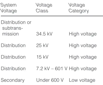
After the transmission-scale power has been reduced in voltage at the substation, it is then sent along smaller distribution lines to end users such as smaller businesses, homes and farms. We all recognize these lines as the lines that run near our houses. Often, a smaller transformer will be located on a pole where the distribution line branches into the business or home.
Table 6. Common distribution voltages.
System Voltage Voltage Voltage Class Category
Distribution or
mission 34.5 kV High voltage Distribution 25 kV High voltage Distribution 15 kV High voltage Distribution 7.2 kV – 601 V High voltage Secondary Under 600 V Low voltage Source: Electric Power System Basics, p. 103
In neighborhoods, underground distribution lines may sometimes be used to avoid some of the issues with overhead lines. As previous-ly discussed, these lines are more expensive and can be difficult to repair. With underground lines, access trunks and vaults (allowing the utility to reach connections between cables) and ground-based transformers are needed.
Business or home
service entry
The electrical power is almost to your home or business now. The transformer mounted on the distribution pole or trunk will make one final step down to convert the voltage going to your house to 240 volts. Typically, there will be three lines (sometimes called legs ) into the home or business: two 120 V hot wires and a neutral. Most of the circuits in your home will be wired by using one of the 120 V wires and the neu-tral, thus providing the 120 V power needed by many appliances, lights and other items in the home. Some items that demand a lot of power, such as air conditioners, electric clothes dry-ers, water heaters and ovens may require 240 V power. This is accomplished by using the two 120 V wires in combination.
These wires will first pass through an elec-trical meter. Your elecelec-trical meter is simply a watt meter that measures the amount of energy passing through it over time.15 Thus, the meter
records the amount of energy used in the cir-cuits to which it is connected in kilowatt-hours (kWh). Remember, a kWh is the use of one kilo-watt continuously over the course of an hour. The wires, having passed through the meter, then connect to a breaker box (sometimes called a service panel ). This breaker box con-tains a series of circuit breakers that may bridge between the neutral wire and one of the 120 V wires to provide a 120 V circuit or between both 120 V wires and the neutral to provide a 240 V circuit. These breakers serve an important safety function. Recall that if too much current starts to flow through a conductor, it can gener-ate a tremendous amount of heat. Thus, if there is a short circuit or other fault in a business or home circuit, this can dramatically increase current flow and thus create a risk of fire. The circuit breakers work to prevent this by opening themselves if too much current begins to flow in a circuit. This breaks the circuit, preventing any more current from flowing.
We have now gotten the power all the way from the generator to your home or business. But we also know that this process is not free, because we get an electric bill each month.
How do power
companies buy power
from generators and
sell it to customers,
and how are these
prices set?
Participants
in the electrical market
Earlier, we discussed the fact that ISOs and RTOs coordinate the activities of everyone in-volved in the supply and transmission of power within their jurisdiction. But who are these enti-ties, and how do they work together to create a market where electrical power can be bought, delivered, and sold to customers?
There are a number of participants in the electrical market, but they can be divided into generators, transmission entities, regulatory agencies and customers.
Generators
When you think of electric company, the two things that probably come into your mind first are power plants and electrical lines (though we could probably add your electrical bill as a third item). Many times, the same company that owns the equipment to generate electricity also owns the transmission lines, but this is not always the case, which is why we discuss gen-erators separately from transmission entities.
The majority of the United States’ electrical customers are served by investor-owned util-ities (IOUs).16 IOUs are owned by their
share-holders, and their shares are sometimes bought and sold on stock exchanges like the New York Stock Exchange. In Oklahoma, the two largest investor-owned utilities are Oklahoma Gas and Electric (OG&E) and American Electric Power – Public Service Company of Oklahoma (AEP-PSO). Traditionally, IOUs own both a large fleet of electrical generators and transmission lines. While this is still the case for OG&E and AEP-PSO, these companies may also enter into contracts with other companies who own gen-erators to provide power (see the discussion regarding merchant generators below).
Rural Electrical Cooperatives (RECs) are another important type of generator, particular-ly in Oklahoma. As the electrical industry was constructing generators and transmission lines in the early part of the 20th century, many ru-ral areas were being left without service. Cus-tomers in these areas were so spread out that for-profit electrical providers did not believe they could be profitable. As a result, these customers joined together and formed their own customer-owned utilities, facilitated by loans authorized under the Rural Electrification Act.17 Customers buy in to the cooperative by
purchasing electrical service from it, and if the cooperative takes in revenues above its costs, those earnings are re-distributed to the mem-bers in proportion to their patronage (i.e. the volume of business they did with the ative). Oklahoma’s largest generating
cooper-ative is Western Farmers Electric Coopercooper-ative (WFEC). Nationally, electric cooperatives serve 12 percent of electric customers.18
Municipal utilities also play a role in gener-ating electricity. Usually, municipal utilities are tasked with providing power to the residents of a particular town or specific area. Munici-pal utilities may generate their own power, but they often purchase it from another generator. In Oklahoma, many municipal utilities purchase their power from the Oklahoma Municipal Pow-er Authority (OMPA). The OMPA is unique in that it functions as both a state agency and as a generating utility owned by its member mu-nicipal utilities. These utilities supply about 14 percent of U.S. customers.19
Federal power agencies are another type of generator. These agencies market the elec-trical power produced by federal assets (most commonly, hydroelectric dams). For example, one of the most famous federal generation as-sets is Hoover Dam. Hoover Dam is a hydro-electric power plant located in Nevada that is powered by the water stored in Lake Mead, which was formed by damming the Colorado River. The dam and its hydroelectric genera-tion equipment are owned and operated by the federal Bureau of Reclamation. The power from the hydroelectric generator is then marketed through a federal power agency – the Western Area Power Administration (WAPA) – to a num-ber of municipalities in Nevada, Arizona and California.
Merchant generators and independent power producers (IPPs) are entities that are not part of a utility but instead generate electrical power to sell to utilities. They may build their own generator facilities or buy facilities from other entities. The primary difference between merchant generators and IPPs is merchant generators frequently sell their power to a num-ber of utilities based on current market prices, while IPPs generally enter into long-term con-tracts to sell power to one or a few utilities at a set price.
Transmission entities
The ownership of transmission and distribu-tion lines may be divided in a number of dif-16 Understanding Todays’ Electrical Business, p. 85,
citing data from the American Public Power Asso-ciation 2009-10 Annual Directory and Statistical Re-port.
17 7 U.S.C. §§ 902 – 918a.
18 Understanding Today’s Electrical Business, p. 87. 19 Understanding Today’s Electrical Business, p. 86.
ferent ways. Many times, the same entity that owns the generators will also own transmission and distribution lines. This is how many OG&E and AEP-PSO customers are served. In other cases, utilities may own only generators and transmission lines, and then another utility will own local distribution lines. For example, WFEC owns generators and transmission lines, and then sells power to local distribution coopera-tives that own and operate the local distribution lines.
Increasingly, though, there are companies that do not own any generators but focus solely on building and operating transmission lines. These companies are sometimes called trans-mission companies or transcos. These entities contract with utilities to provide access to their transmission lines. They also can contract with ISOs and RTOs to build transmission capacity for the grid. In Oklahoma, transmission compa-nies can be given public utility status.20 In the
future, transmission entities may play a larger role in providing transmission infrastructure.
Regulatory agencies
No discussion of the electrical industry’s structure would be complete without a dis-cussion of how it is regulated. At the federal level, the Federal Energy Regulatory Commis-sion (FERC) has jurisdiction over the interstate transmission of electrical power. This means FERC governs many aspects of the electrical generation and transmission process for many IOUs, merchant generators, IPPs and transmis-sion entities. FERC also oversees many facets of ISO and RTO operations. In short, if an entity contemplates building a new electrical gener-ation project or transmission project, it is likely FERC will be involved at some stage.
At the state level, much of Oklahoma’s elec-trical industry is regulated by the Oklahoma Corporation Commission’s (OCC) Public Util-ity Division (PUD). The OCC is charged with regulating the operation of IOUs in Oklahoma. However, it does not have jurisdiction over gen-eration and transmission cooperatives or
mu-nicipal utilities that are part of the OMPA.
While FERC and OCC handle many of the regulatory issues governing the generation, transmission and sale of power, there can be a number of other agencies that deal with issues impacting the electrical industry. For example, since many electrical projects will have envi-ronmental impacts, agencies like the federal Environmental Protection Agency (EPA) and the Oklahoma Department of Environmental Quali-ty (ODEQ) may become involved. For example, although it is not strictly an electrical utility stat-ute, the Clean Air Act and its regulations have significant impacts on what fuel sources are and will be used in generating electrical pow-er. In areas with endangered species of plants and animals, the U.S. Fish and Wildlife Service (FWS) or the Oklahoma Department of Wildlife Conservation (ODWC) may be involved as well.
In addition to these agencies, there are also a large number of laws that impact the struc-ture and operation of the electrical industry. Two of these are particularly important to our discussion. The first, the Public Utilities Hold-ing Company Act (PUHCA) limited the types of businesses in which electrical utility holding companies could participate and largely limit-ed utilities to operations within a state. Although PUHCA was repealed by the 2005 Energy Pol-icy Act,21 its effects on the electrical industry’s
structure are still visible.
Another important law for the electrical in-dustry, and particularly for the wind inin-dustry, is the Public Utilities Regulatory Policies Act of 1978 (PURPA). Among many other provisions, PURPA requires electrical utilities to purchase energy from qualified facilities at the avoided cost of that electricity. Qualifying facilities in-clude many cogeneration facilities and renew-able energy facilities such as wind energy proj-ects.22 Avoided cost (also called incremental
cost ) is defined as what it would cost the elec-trical utility to generate the amount of power generated by the qualifying facility.23 While the
20 A public utility is defined by 17 Okla. Stat. §§ 151.
For example, Plains and Eastern Clean Line Oklaho-ma LLC, ( Plains and Eastern ), a transmission-only company, was given public utility status in 2010 by the Oklahoma Corporation Commission. OCC Joint Stipulation and Settlement Agreement, OCC Cause No. PUD 201000075.
21 Pub. L. 109-58, § 1263
22 Qualifying facility was the term originally used un-der PURPA. With the amendments made to PUR-PA by the Energy Policy Act of 2005, this term has been replaced with qualifying small power produc-tion facility or cogeneraproduc-tion facility. See 16 U.S.C. § 796(17)(C)